
Related Manuals for Beckhoff KL3222


Summary of Contents for Beckhoff KL3222
- Page 1 Documentation KL3222 2 Channel Accurate Input Terminals for PT100 (RTD) Version: 2.3.0 Date: 2019-09-24...
-
Page 3: Table Of Contents
Table of contents Table of contents 1 Foreword .............................. 5 Notes on the documentation...................... 5 Safety instructions .......................... 6 Documentation issue versions...................... 7 Beckhoff Identification Code (BIC) .................... 8 2 Product overview............................. 10 Introduction ............................ 10 Technical data .......................... 11 3 Mounting and wiring.......................... 12 Instructions for ESD protection ...................... 12 Installation on mounting rails ...................... 12... - Page 4 Table of contents Version: 2.3.0 KL3222...
-
Page 5: Foreword
EP1590927, EP1789857, EP1456722, EP2137893, DE102015105702 with corresponding applications or registrations in various other countries. ® EtherCAT is registered trademark and patented technology, licensed by Beckhoff Automation GmbH, Germany. Copyright © Beckhoff Automation GmbH & Co. KG, Germany. The reproduction, distribution and utilization of this document as well as the communication of its contents to others without express authorization are prohibited. -
Page 6: Safety Instructions
All the components are supplied in particular hardware and software configurations appropriate for the application. Modifications to hardware or software configurations other than those described in the documentation are not permitted, and nullify the liability of Beckhoff Automation GmbH & Co. KG. Personnel qualification This description is only intended for trained specialists in control, automation and drive engineering who are familiar with the applicable national standards. -
Page 7: Documentation Issue Versions
Foreword Documentation issue versions Version Comment 2.3.0 • Update chapter “Instructions for ESD protection” • Chapter “Beckhoff Identification Code (BIC) added 2.2.0 • Update chapter “Introduction” • Update chapter “Technical data” • Update chapter “Register description” • Update structure 2.1.0 •... -
Page 8: Beckhoff Identification Code (Bic)
Foreword Beckhoff Identification Code (BIC) The Beckhoff Identification Code (BIC) is increasingly being applied to Beckhoff products to uniquely identify the product. The BIC is represented as a Data Matrix Code (DMC, code scheme ECC200), the content is based on the ANSI standard MH10.8.2-2016. - Page 9 Example of composite information from item 1 to 4 and 6. The data identifiers are marked in red for better display: An important component of the BIC is the Beckhoff Traceability Number (BTN, item no. 2). The BTN is a unique serial number consisting of eight characters that will replace all other serial number systems at Beckhoff in the long term (e.g.
-
Page 10: Product Overview
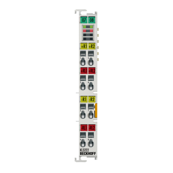
Introduction Fig. 2: KL3222 The KL3222 analog input terminal allows the direct connection of resistance sensors in 4-wire connection technology; external jumpers must be used for 2/3-wire connection technology. Linearization over the full temperature range is realized with the aid of a microprocessor. The temperature range can be selected freely. -
Page 11: Technical Data
CE, cULus, ATEX [} 22] The KL3222 is designed for 4-wire measurement The KL3222 is designed for 4-wire measurement. +R/-R are the current-carrying connection cables, +RL/-RL are the currentless sense cables. If a sensor is to be connected using 2/3 wire connection technology and the KL3202 cannot be used, the following applies •... -
Page 12: Mounting And Wiring
• Each assembly must be terminated at the right hand end with a KL9010 bus end terminal, to ensure the protection class and ESD protection. Fig. 3: Spring contacts of the Beckhoff I/O components Installation on mounting rails WARNING... -
Page 13: Fig. 4 Attaching On Mounting Rail
To mount the mounting rails with a height of 7.5 mm under the terminals and couplers, you should use flat mounting connections (e.g. countersunk screws or blind rivets). KL3222 Version: 2.3.0... -
Page 14: Fig. 5 Disassembling Of Terminal
EL91xx, EL92xx) interrupt the power contacts and thus represent the start of a new supply rail. PE power contact The power contact labeled PE can be used as a protective earth. For safety reasons this contact mates first when plugging together, and can ground short-circuit currents of up to 125 A. Version: 2.3.0 KL3222... -
Page 15: Fig. 6 Power Contact On Left Side
Power Feed Terminals can be released and pulled at least 10 mm from the group of terminals. WARNING Risk of electric shock! The PE power contact must not be used for other potentials! KL3222 Version: 2.3.0... -
Page 16: Installation Instructions For Enhanced Mechanical Load Capacity
• Use countersunk head screws to fasten the mounting rail • The free length between the strain relief and the wire connection should be kept as short as possible. A distance of approx. 10 cm should be maintained to the cable duct. Version: 2.3.0 KL3222... -
Page 17: Connection
Insert the new component and plug in the connector with the wiring. This reduces the installation time and eliminates the risk of wires being mixed up. The familiar dimensions of the terminal only had to be changed slightly. The new connector adds about 3 mm. The maximum height of the terminal remains unchanged. KL3222 Version: 2.3.0... -
Page 18: Wiring
"bonded" (ultrasonically welded) conductors. In this case, please note the tables concerning the wire-size width below! 3.4.2 Wiring WARNING Risk of electric shock and damage of device! Bring the bus terminal system into a safe, powered down state before starting installation, disassembly or wiring of the Bus Terminals! Version: 2.3.0 KL3222... -
Page 19: Fig. 10 Connecting A Cable On A Terminal Point
0.08 ... 1.5 mm Wire size width (fine-wire conductors) 0.25 ... 1.5 mm Wire size width (conductors with a wire end sleeve) 0.14 ... 0.75 mm Wire size width (ultrasonically “bonded" conductors) only 1.5 mm Wire stripping length 8 ... 9 mm KL3222 Version: 2.3.0... -
Page 20: Shielding
Mounting and wiring 3.4.3 Shielding Shielding Encoder, analog sensors and actors should always be connected with shielded, twisted paired wires. Version: 2.3.0 KL3222... -
Page 21: Pin Assignment
Risk of injury through electric shock and damage to the device! Bring the Bus Terminals system into a safe, de-energized state before starting mounting, disassembly or wiring of the Bus Terminals! Fig. 11: Pin assignment KL3222 Terminal point Connection for Channel 1: +R... -
Page 22: Atex - Special Conditions (Standard Temperature Range)
80°C at the wire branching points, then cables must be selected whose tempera- ture data correspond to the actual measured temperature values! • Observe the permissible ambient temperature range of 0 to 55°C for the use of Beckhoff fieldbus compo- nents standard temperature range in potentially explosive areas! •... -
Page 23: Atex Documentation
Notes about operation of the Beckhoff terminal systems in potentially explosive ar- eas (ATEX) Pay also attention to the continuative documentation Notes about operation of the Beckhoff terminal systems in potentially explosive areas (ATEX) that is available in the download area of the Beckhoff homepage http:\\www.beckhoff.com! KL3222... -
Page 24: Configuration Software Ks2000
Fieldbus Box modules with the aid of which settings can be modified easily. Alternatively, you have full access to all internal registers of the bus couplers and intelligent terminals. Refer to the register description for the meanings of the registers. Version: 2.3.0 KL3222... - Page 25 • Process values can be specified in the output image for commissioning of the output modules. All possibilities in the online mode can be used in parallel with the actual fieldbus mode of the terminal station. The fieldbus protocol always has the higher priority in this case. KL3222 Version: 2.3.0...
-
Page 26: Parameterization With Ks2000
In the example shown, this is: • an Ethernet Coupler BK9000 • a digital input terminal KL1xx2 • a KL3222 • a KL9010 bus end terminal Fig. 13: Display of the fieldbus station in KS2000 The left-hand KS2000 window displays the terminals of the fieldbus station in a tree structure. -
Page 27: Settings
For the KL3222, the branches Register, Settings and ProcData are displayed: • Register enables direct access to the KL3222 registers. • The dialog mask for the parameterization of the KL3222 can be found under Settings [} 27]. • ProcData displays the KL3222 process data. - Page 28 • 3750 Hz • 7500 Hz • 15000 Hz • 30000 Hz • 5 Hz • 10 Hz Resistance thermometer (sensor type) Here you can adjust the KL3222 to the connected sensor type (R32.15-R32.08 [} 37]): • PT100 • NI100 • PT1000 • PT500 • PT200 • NI1000 •...
-
Page 29: Sample Program For Kl Register Communication Via Ethercat On Kl3314 Exemplary
This example program (TwinCAT 3) provides change of single register values of the KL3314 as selection of the element type, characteristical settings of the feature register R32 and user scaling offset and gain (R33/ R34) similar as per KS2000. KL3222 Version: 2.3.0... -
Page 30: Fig. 16: Settings Of Kl3314 Via Visualisation Of Twincat 3
[coupler (e.g. BK1120) or embedded PC] + KL3314 + KL9010. Download: https://infosys.beckhoff.com/content/1033/kl3222/Resources/zip/5996114571.zip Preparations for starting the sample programs (tnzip file / TwinCAT 3) • Click on the download button to save the Zip archive locally on your hard disk, then unzip the *.tnzip archive file in a temporary folder. -
Page 31: Fig. 18 Search Of The Existing Hw Configuration For The Ethercat Configuration Of The Example
"Change NetId..." have to be selected. The first 4 numbers of the NetId of the target computer have to be entered; the both last values are 4.1 usually. Example: ◦ NetId of project: myComputer (123.45.67.89.1.1) ◦ Entry via „Change NetId...“: 123.45.67.89.4.1 KL3222 Version: 2.3.0... -
Page 32: Access From The User Program
Access from the user program Process image Complete process image The KL3222/KS3222 is represented in the complex process image with 6 bytes of input data and 2 bytes of output data. These are organized as follows: Byte offset (without word Byte offset (with word align-... -
Page 33: Control And Status Bytes
SB1.0 Name RegAccess Error Overrange Underrange Name Description SB1.7 RegAccess Acknowledgment for process data mode SB1.6 Error General error bit SB1.5 .. reserved . SB1.2 SB1.1 Overrange Process data too large SB1.0 Underrange 1 Process data too small KL3222 Version: 2.3.0... -
Page 34: Register Communication
SB1.5 SB1.4 SB1.3 SB1.2 SB1.1 SB1.0 Name RegAccess R/W Reg. no. Name Description SB1.7 RegAccess 1 Acknowledgment for register access SB1.6 Read access SB1.5 to Reg. no. Number of the register that was read or written. SB1.0 Version: 2.3.0 KL3222... -
Page 35: Register Overview
0x0000 0dec R31 [} 36] Feature register 0x0000 0dec SEEPROM R32 [} 37] User scaling: Offset 0x0000 SEEPROM R33 [} 38] User scaling: Gain 0x0100 SEEPROM R34 [} 38] Filter 0x0000 SEEPROM R37 [} 38] reserved 0x0000 SEEPROM reserved reserved 0x0000 SEEPROM KL3222 Version: 2.3.0... -
Page 36: Register Description
The command register of KL3222 is currently not used. • R8: terminal designation Register R8 contains the name of the terminal: KL3222: 0x0C9C (3222 • R9: firmware version Register R9 contains the ASCII coding of the terminal's firmware version, e.g. 0x3141 = '1A'. The '0x31' corresponds here to the ASCII character '1', while the '0x41' represents the ASCII character 'A'. - Page 37 Siemens format not active Siemens format active R32.3 reserved R32.2 Watchdog Watchdog not active Watchdog active R32.1 enManScal Manufacturer scaling is not active Manufacturer scaling is active R32.0 enUsrScal User scaling is not active User scaling is active KL3222 Version: 2.3.0...
-
Page 38: Examples Of Register Communication
• The terminal returns the firmware version 0x3341 in the input data word (byte 1 and byte 2). This is to be interpreted as an ASCII code: ◦ ASCII code 0x33 represents the digit 3 ◦ ASCII code 0x41 represents the letter A The firmware version is thus 3A. Version: 2.3.0 KL3222... -
Page 39: Example 2: Writing To An User Register
Byte 0: Status byte Byte 1: DataIN1, high byte Byte 2: DataIN1, low byte 0x9F (1001 1111 0x12 0x35 Explanation: • The terminal returns the value of the control byte as a receipt in the status byte. KL3222 Version: 2.3.0... - Page 40 • The terminal returns the value of the control byte as a receipt in the status byte. • The terminal returns the current value of the feature register in the input data word (byte 1 and byte 2). Version: 2.3.0 KL3222...
- Page 41 • The terminal returns a value as a receipt in the status byte that differs only in bit 0.6 from the value of the control byte. • The input data word (byte 1 and byte 2) is of no importance after the write access. Any values still displayed are invalid! KL3222 Version: 2.3.0...
-
Page 42: Appendix
Beckhoff's branch offices and representatives Please contact your Beckhoff branch office or representative for local support and service on Beckhoff products! The addresses of Beckhoff's branch offices and representatives round the world can be found on her internet pages: http://www.beckhoff.com You will also find further documentation for Beckhoff components there. - Page 43 KS2000 configuration software....................Fig. 13 Display of the fieldbus station in KS2000 ..................Fig. 14 KS2000 branch for channel 1 of the KL3222................Fig. 15 Settings via KS2000 ........................Fig. 16 Settings of KL3314 via visualisation of TwinCAT 3 ..............
Need help?
Do you have a question about the KL3222 and is the answer not in the manual?
Questions and answers