Sign In
Upload
Download
Table of Contents
Contents
Add to my manuals
Delete from my manuals
Share
URL of this page:
HTML Link:
Bookmark this page
Add
Manual will be automatically added to "My Manuals"
Print this page
×
Bookmark added
×
Added to my manuals
Manuals
Brands
Beckhoff Manuals
Touch terminals
KL4414
Documentation
Beckhoff KL4414 Documentation
Four- and eightchannel, analog output terminals
Hide thumbs
1
2
3
4
5
6
7
8
9
10
11
12
13
14
15
16
17
18
19
20
21
22
23
24
25
26
27
28
29
30
31
32
33
34
35
36
37
38
39
40
41
42
43
44
45
page
of
45
Go
/
45
Contents
Table of Contents
Bookmarks
Table of Contents
Table of Contents
1 Foreword
Notes on the Documentation
Safety Instructions
Documentation Issue Status
Fig. 5 KL4428
Fig. 17 KL4418
2 KL4414, KL4424 - Product Overview
Introduction
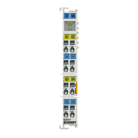
Fig. 1 KL4414
Fig. 2 KL4424
Technical Data
Diagnostic Leds
Fig. 3 KL4414, KL4424, - Leds
3 KL4418, KL4428 - Product Overview
Introduction
Technical Data
Diagnostic Leds
Fig. 6 KL4418, KL4428 - Leds
4 Basic Function Principles
5 Mounting and Wiring
Instructions for ESD Protection
Installation on Mounting Rails
Fig. 7 Spring Contacts of the Beckhoff I/O Components
Fig. 8 Attaching on Mounting Rail
Fig. 9 Disassembling of Terminal
Fig. 10 Power Contact on Left Side
Installation Instructions for Enhanced Mechanical Load Capacity
Connection
Connection System
Fig. 11 Standard Wiring
Fig. 12 Pluggable Wiring
Wiring
Fig. 14 Connecting a Cable on a Terminal Point
Shielding
Fig. 13 High Density Terminals
KL4414, KL4424 - Connection
Fig. 15 KL4414
Fig. 16 KL4424
KL4418, KL4428 - Connection
Fig. 4 KL4418
Fig. 18 KL4428
ATEX - Special Conditions (Standard Temperature Range)
ATEX Documentation
6 KS2000 Configuration Software
KS2000 - Introduction
Fig. 19 KS2000 Configuration Software
Parameterization with KS2000
Fig. 20 Display of the Fieldbus Station in KS2000
Fig. 21 KS2000 Branches for Channel 1 of the KL4414
Settings
Fig. 22 Settings Via KS2000
Register
Process Data
Fig. 23 Register View in KS2000
Fig. 24 Process Data Field
Fig. 25 History Field
Fig. 26 Value Field - Display of the Input Value
Fig. 27 Value Field for Entering the Output Values
Fig. 28 Setting the Display
7 Access from the User Program
Process Image
Mapping
Control and Status Bytes
Register Overview
Register Description
8 Examples of Register Communication
Example 1: Reading the Firmware Version from Register 9
Example 2: Writing to an User Register
9 Appendix
Support and Service
List of Illustrations
Advertisement
Quick Links
1
Fig. 2 Kl4424
Download this manual
Documentation
KL4414, KL4418, KL4424, KL4428
Four- and eightchannel, analog output terminals
Version:
Date:
3.0.0
2017-09-15
Table of
Contents
Previous
Page
Next
Page
1
2
3
4
5
Advertisement
Chapters
Table of Contents
3
List of Illustrations
45
Table of Contents
Need help?
Do you have a question about the KL4414 and is the answer not in the manual?
Ask a question
Questions and answers
Related Manuals for Beckhoff KL4414
Touch terminals Beckhoff KL4011 Operating Instructions Manual
Single- and two-channel analog output terminals (19 pages)
Touch terminals Beckhoff KL401 Series Documentation
Single- and dual-channel analog output terminals 0 to 20 ma and 4 to 20 ma (42 pages)
Touch terminals Beckhoff KL4494 Manual
Analog terminal with two input and two output channels, (-10v...+10v) (40 pages)
Touch terminals Beckhoff KL403 Series Documentation
Single-, dual- and four-channel analog output terminals, signal range: -10 v to +10 v (46 pages)
Touch terminals Beckhoff KL4031 Documentation
Single-, dual- and four-channel analog output terminals, signal range: -10 v to +10 v (46 pages)
Touch terminals Beckhoff KL4032 Documentation
Single-, dual- and four-channel analog output terminals, signal range: -10 v to +10 v (46 pages)
Touch terminals Beckhoff KL4034 Documentation
Single-, dual- and four-channel analog output terminals, signal range: -10 v to +10 v (46 pages)
Touch terminals Beckhoff KL4418 Documentation
Four- and eightchannel, analog output terminals (45 pages)
Touch terminals Beckhoff KL4424 Documentation
Four- and eightchannel, analog output terminals (45 pages)
Touch terminals Beckhoff KL4428 Documentation
Four- and eightchannel, analog output terminals (45 pages)
Touch terminals Beckhoff KL400 Series Documentation
Single-, dual and four-channel analog output terminals, (0v...10v) (42 pages)
Touch terminals Beckhoff KL4132 Documentation
Dual-channel analog output terminal, -10 v to +10 v, 16 bit (38 pages)
Touch terminals Beckhoff KL4112 Documentation
Dual channel analog output terminal, 0 to 20 ma, 16 bit (38 pages)
Touch terminals Beckhoff KL2761 Documentation
Single channel universal dimmer terminals (54 pages)
Touch terminals Beckhoff KL9060 Documentation
Power terminal for siemens contactors of the sirius 3rt10 series (47 pages)
Touch terminals Beckhoff KL3182 Manual
Two channel accurate analog terminals (63 pages)
This manual is also suitable for:
Kl4418
Kl4424
Kl4428
Table of Contents
Print
Rename the bookmark
Delete bookmark?
Delete from my manuals?
Login
Sign In
OR
Sign in with Facebook
Sign in with Google
Upload manual
Upload from disk
Upload from URL


Need help?
Do you have a question about the KL4414 and is the answer not in the manual?
Questions and answers