
Subscribe to Our Youtube Channel
Related Manuals for Beckhoff KL3444


Summary of Contents for Beckhoff KL3444
- Page 1 Documentation KL3444, KL3448, KL3454 und KL3458 four and eight channel analog input terminals Version: 3.2.0 Date: 2019-10-16...
-
Page 3: Table Of Contents
1 Foreword .............................. 5 Notes on the documentation...................... 5 Safety instructions .......................... 6 Documentation Issue Status...................... 7 Beckhoff Identification Code (BIC) .................... 8 2 KL3444, KL3454 - Product Overview ..................... 10 Introduction ............................ 10 Technical Data.......................... 12 Diagnostic LEDs .......................... 13 3 KL3448, KL3458 - Product Overview ..................... 14 Introduction ............................ 14 Technical Data.......................... 16... - Page 4 Table of contents Examples of Register Communication .................... 53 7.6.1 Example 1: reading the firmware version from Register 9.......... 53 7.6.2 Example 2: Writing to an user register................ 54 8 Appendix .............................. 57 Support and Service ........................ 57 Version: 3.2.0 KL3444, KL3448, KL3454 und KL3458...
-
Page 5: Foreword
EP1590927, EP1789857, EP1456722, EP2137893, DE102015105702 with corresponding applications or registrations in various other countries. ® EtherCAT is registered trademark and patented technology, licensed by Beckhoff Automation GmbH, Germany. Copyright © Beckhoff Automation GmbH & Co. KG, Germany. The reproduction, distribution and utilization of this document as well as the communication of its contents to others without express authorization are prohibited. -
Page 6: Safety Instructions
All the components are supplied in particular hardware and software configurations appropriate for the application. Modifications to hardware or software configurations other than those described in the documentation are not permitted, and nullify the liability of Beckhoff Automation GmbH & Co. KG. Personnel qualification This description is only intended for trained specialists in control, automation and drive engineering who are familiar with the applicable national standards. -
Page 7: Documentation Issue Status
Documentation Issue Status Version Comment 3.2.0 • Update chapter “Instructions for ESD protection” • Chapter “Beckhoff Identification Code (BIC)” added 3.1.0 • Design of the safety instructions adapted to IEC 82079-1 • Update Technical data • Chapter Instructions for ESD protection added •... -
Page 8: Beckhoff Identification Code (Bic)
01 - hardware version 01 Beckhoff Identification Code (BIC) The Beckhoff Identification Code (BIC) is increasingly being applied to Beckhoff products to uniquely identify the product. The BIC is represented as a Data Matrix Code (DMC, code scheme ECC200), the content is based on the ANSI standard MH10.8.2-2016. - Page 9 Example of composite information from item 1 to 4 and 6. The data identifiers are marked in red for better display: An important component of the BIC is the Beckhoff Traceability Number (BTN, item no. 2). The BTN is a unique serial number consisting of eight characters that will replace all other serial number systems at Beckhoff in the long term (e.g.
-
Page 10: Kl3444, Kl3454 - Product Overview
12 bits, and is transmitted, in an electrically isolated form, to the higher-level automation device. In the KL3444 Bus Terminal, the four inputs are 2-wire versions and have a common ground potential. This reference ground of the inputs is electrically isolated from the 0 V power contact. The power contacts are connected through. -
Page 11: Fig. 3 Kl3454
KL3444, KL3454 - Product Overview KL3454: 4-channel analog input terminal 4 ... 20 mA Fig. 3: KL3454 The EL3454 analog input terminal process signals in the range between 4 and 20 mA. The current is digitized to a resolution of 12 bits, and is transmitted, in an electrically isolated form, to the higher-level automation device. -
Page 12: Technical Data
KL3444, KL3454 - Product Overview Technical Data Technical Data KL3444-0000, KS3444-0000 KL3454-0000, KS3454-0000 Number of inputs Signal voltage 0 ... 20 mA 4 ... 20 mA Internal resistance < 85 Ω Common-mode voltage U max. 30 V max. 30 V Resolution 12 Bit Conversion time approx. 2 ms Measuring error (total measuring range) <... -
Page 13: Diagnostic Leds
KL3444, KL3454 - Product Overview Diagnostic LEDs The four green RUN LEDs and the four red Error LEDs indicate the operating states of the terminal channels. Fig. 4: KL3444, KL3454 - Diagnostic LEDs Meaning of the LED displays Color Channel State... -
Page 14: Kl3448, Kl3458 - Product Overview
The reference ground for all inputs is the 0 V power contact. Overload is detected and the terminal status is forwarded to the controller via the K-bus. The Run LEDs give an indication of the data exchange with the Bus Coupler. Version: 3.2.0 KL3444, KL3448, KL3454 und KL3458... -
Page 15: Fig. 6 Kl3458
The reference ground for all inputs is the 0 V power contact. Overload is detected and the terminal status is forwarded to the controller via the K-bus. The Error LEDs indicate overload and wire breakage. KL3444, KL3448, KL3454 und KL3458 Version: 3.2.0... -
Page 16: Technical Data
Vibration / shock resistance conforms to EN 60068-2-6/EN 60068-2-27, see also Installation instructions for enhanced mechanical load capacity [} 24] EMC immunity / emission conforms to EN 61000-6-2 / EN 61000-6-4 Protection class IP20 Installation position variable Approval CE, cULus, ATEX [} 31], GL Version: 3.2.0 KL3444, KL3448, KL3454 und KL3458... -
Page 17: Kl3448 - Diagnostic Leds
A watchdog timer overflow has occurred. The green LEDs go out if Run 2 no process data are transferred Run 3 between the controller and the Bus Run 4 Coupler for more than 100 ms. Run 5 Run 6 Run 7 Run 8 KL3444, KL3448, KL3454 und KL3458 Version: 3.2.0... -
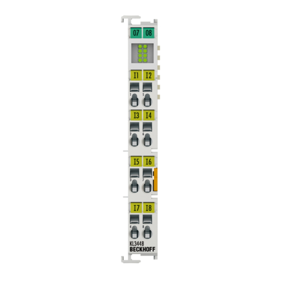
Page 18: Kl3458 - Diagnostic Leds
The eight red Error LEDs indicate the operating states of the terminal channels. Fig. 8: KL3458 - Diagnostic LEDs Meaning of the LED displays Color Channel State Error 1 Channel current greater than normal operation 20.8 mA Error 2 Error 3 Error 4 Error 5 Error 6 Error 7 Error 8 Version: 3.2.0 KL3444, KL3448, KL3454 und KL3458... -
Page 19: Basic Function Principles
Basic Function Principles The analog input terminals • KL3444 and KL3448 process signals in the range between 0 and 20 mA • KL3454 and KL3458 process signals in the range between 4 and 20 mA with a resolution of 12 bits (4095 steps). They can supply the sensors from voltage fed in via the power contacts. -
Page 20: Fig. 9 Signal Processing
Basic Function Principles The equations of the straight line are enabled via register R32. Fig. 9: Signal processing Version: 3.2.0 KL3444, KL3448, KL3454 und KL3458... -
Page 21: Mounting And Wiring
• Each assembly must be terminated at the right hand end with a KL9010 bus end terminal, to ensure the protection class and ESD protection. Fig. 10: Spring contacts of the Beckhoff I/O components Installation on mounting rails WARNING... -
Page 22: Fig. 11 Attaching On Mounting Rail
To mount the mounting rails with a height of 7.5 mm under the terminals and couplers, you should use flat mounting connections (e.g. countersunk screws or blind rivets). Version: 3.2.0 KL3444, KL3448, KL3454 und KL3458... -
Page 23: Fig. 12 Disassembling Of Terminal
PE power contact The power contact labeled PE can be used as a protective earth. For safety reasons this contact mates first when plugging together, and can ground short-circuit currents of up to 125 A. KL3444, KL3448, KL3454 und KL3458 Version: 3.2.0... -
Page 24: Installation Instructions For Enhanced Mechanical Load Capacity
10 frequency runs in 3 axes 6 Hz < f < 60 Hz displacement 0.35 mm, constant amplitude 60.1 Hz < f < 500 Hz acceleration 5 g, constant amplitude Shocks 1000 shocks in each direction, in 3 axes 25 g, 6 ms Version: 3.2.0 KL3444, KL3448, KL3454 und KL3458... -
Page 25: Connection
Standard wiring (ELxxxx / KLxxxx) Fig. 14: Standard wiring The terminals of ELxxxx and KLxxxx series have been tried and tested for years. They feature integrated screwless spring force technology for fast and simple assembly. KL3444, KL3448, KL3454 und KL3458 Version: 3.2.0... -
Page 26: Fig. 15 Pluggable Wiring
Ultrasonically “bonded" conductors It is also possible to connect the Standard and High Density Terminals with ultrasonically "bonded" (ultrasonically welded) conductors. In this case, please note the tables concerning the wire-size width below! Version: 3.2.0 KL3444, KL3448, KL3454 und KL3458... -
Page 27: Wiring
The cables are released, as usual, using the contact release with the aid of a screwdriver. See the following table for the suitable wire size width. KL3444, KL3448, KL3454 und KL3458 Version: 3.2.0... -
Page 28: Shielding
Connection for Input 1 Input 1, signal Input 1, ground Input 3 Input 3, signal Input 3, ground Input 2 Input 2, signal Input 2, ground Input 4 Input 4, signal Input 4, ground Version: 3.2.0 KL3444, KL3448, KL3454 und KL3458... -
Page 29: Kl3454 - Connection
Input 1, 24 V Input 3 Input 3, signal + 24 V Input 3, 24 V Input 2 Input 2, signal + 24 V Input 2, 24 V Input 4 Input 4, signal + 24 V Input 4, 24 V KL3444, KL3448, KL3454 und KL3458 Version: 3.2.0... -
Page 30: Kl3448, Kl3458 - Connection
Input 3, signal Input 5 Input 5, signal Input 7 Input 7, signal Input 2 Input 2, signal Input 4 Input 4, signal Input 6 Input 6, signal Input 8 Input 8, signal Version: 3.2.0 KL3444, KL3448, KL3454 und KL3458... -
Page 31: Atex - Special Conditions (Standard Temperature Range)
80°C at the wire branching points, then cables must be selected whose tempera- ture data correspond to the actual measured temperature values! • Observe the permissible ambient temperature range of 0 to 55°C for the use of Beckhoff fieldbus compo- nents standard temperature range in potentially explosive areas! •... -
Page 32: Atex - Special Conditions (Extended Temperature Range)
80°C at the wire branching points, then cables must be selected whose tempera- ture data correspond to the actual measured temperature values! • Observe the permissible ambient temperature range of -25 to 60°C for the use of Beckhoff fieldbus com- ponents with extended temperature range (ET) in potentially explosive areas! •... -
Page 33: Atex Documentation
Notes about operation of the Beckhoff terminal systems in potentially explosive ar- eas (ATEX) Pay also attention to the continuative documentation Notes about operation of the Beckhoff terminal systems in potentially explosive areas (ATEX) that is available in the download area of the Beckhoff homepage http:\\www.beckhoff.com! KL3444, KL3448, KL3454 und KL3458... -
Page 34: Ks2000 Configuration Software
Fieldbus Box modules with the aid of which settings can be modified easily. Alternatively, you have full access to all internal registers of the bus couplers and intelligent terminals. Refer to the register description for the meanings of the registers. Version: 3.2.0 KL3444, KL3448, KL3454 und KL3458... - Page 35 • Process values can be specified in the output image for commissioning of the output modules. All possibilities in the online mode can be used in parallel with the actual fieldbus mode of the terminal station. The fieldbus protocol always has the higher priority in this case. KL3444, KL3448, KL3454 und KL3458 Version: 3.2.0...
-
Page 36: Parameterization With Ks2000
In the example shown, this is • a BK9000 Bus Coupler for Ethernet • a KL1xx2 Digital Input Terminal • a KL3444 Analog Input Terminal • a KL9010 Bus End Terminal Fig. 22: Display of the fieldbus station in KS2000 The left-hand KS2000 window displays the terminals of the fieldbus station in a tree structure. -
Page 37: Settings
• Dialog masks for the parameterization of the KL3444 can be found under Settings [} 37]. • ProcData displays the KL3444 process data (in preparation). Settings The dialog mask for the parameterization of the KL3444, KL3448, KL3454 or KL3458 can be found under Settings. Fig. 24: Settings via KS2000 Operation mode •... - Page 38 You can specify threshold 2 here. • IIR filter cut-off frequency (R37 [} 53]) You can specify the cut-off frequency for the digital IIR filter here. ◦ KL3444, KL3454: default 200 Hz ◦ KL3448, KL3458: default 100 Hz Version: 3.2.0 KL3444, KL3448, KL3454 und KL3458...
-
Page 39: Register
KS2000 Configuration Software Register Under Register you can directly access the Registers of the KL3444 or KL3454. The meaning of the register is explained in the Register Overview [} 49]. Fig. 25: Register view in KS2000 KL3444, KL3448, KL3454 und KL3458 Version: 3.2.0... -
Page 40: Sample Program For Kl Register Communication Via Ethercat On Kl3314 Exemplary
R32 and user scaling offset and gain (R33/ R34) similar as per KS2000. Fig. 26: Settings of KL3314 via visualisation of TwinCAT 3 At least following configuration setup shall be present: [coupler (e.g. BK1120) or embedded PC] + KL3314 + KL9010. Version: 3.2.0 KL3444, KL3448, KL3454 und KL3458... -
Page 41: Fig. 27 Opening The *. Tnzip Archive
TwinCAT environment above, where a pull down menu can be opened to choose a target system (by clicking right in the text field). The number blocks are placed in brackets there next to each computer name of a target system. KL3444, KL3448, KL3454 und KL3458 Version: 3.2.0... - Page 42 "Change NetId..." have to be selected. The first 4 numbers of the NetId of the target computer have to be entered; the both last values are 4.1 usually. Example: ◦ NetId of project: myComputer (123.45.67.89.1.1) ◦ Entry via „Change NetId...“: 123.45.67.89.4.1 Version: 3.2.0 KL3444, KL3448, KL3454 und KL3458...
-
Page 43: Access From The User Program
Process image KL3404 and KL3464 as well as KL3444 and KL3454 KL3404 and KL3464 as well as KL3444 and KL3454 represent themselves in the process image with up to 12 bytes of input data and 12 bytes of output data. -
Page 44: Mapping
Ch3 D1 Word alignment: any Ch4 D0 Ch4 D1 Complete evaluation: For complete evaluation, the analog input terminals occupy addresses in the input and output process image. Control and status bytes can be accessed. Version: 3.2.0 KL3444, KL3448, KL3454 und KL3458... - Page 45 Word alignment: yes Ch2 D0 Ch2 D1 Ch2 D0 Ch2 D1 reserved reserved Ch3 D0 Ch3 D1 Ch3 D0 Ch3 D1 reserved reserved Ch4 D0 Ch4 D1 Ch4 D0 Ch4 D1 KL3444, KL3448, KL3454 und KL3458 Version: 3.2.0...
- Page 46 Ch n D1: channel n, higher-order data byte reserved: This byte is assigned to the process data memory, although it has no function. "-": This byte is not used or occupied by the terminal/module. Version: 3.2.0 KL3444, KL3448, KL3454 und KL3458...
-
Page 47: Control And Status Bytes
Process data less than limit value 1 Process data greater than limit value 1 Process data equal limit value 1 SB1.1 Overrange Permissible measuring range exceeded SB1.0 Underrange 1 Lower measuring range limit violated KL3444, KL3448, KL3454 und KL3458 Version: 3.2.0... -
Page 48: Register Communication
SB1.1 SB1.0 Name RegAccess R/W Reg. no. Name Description SB1.7 RegAccess 1 Acknowledgment for register access SB1.6 Read access SB1.5 … Reg. no. Number of the register that was read or written. SB1.0 Version: 3.2.0 KL3444, KL3448, KL3454 und KL3458... -
Page 49: Register Overview
Access from the User Program Register Overview The following registers are used to parameterize the KL3444, KL3448, KL3454 and KL3458. Each signal channel of the analog terminal has one register that can be read or written to with the aid of control, status and data bytes [} 43] via register communication. -
Page 50: Register Description
Access from the User Program Register description The following registers are used to parameterize the KL3444, KL3448, KL3454 and KL3458. Each signal channel of the analog terminal has one register that can be read or written to with the aid of control, status and data bytes [} 43] via register communication. - Page 51 (0x1235) in the code word register, these values are stored in the RAM registers and in the SEEPROM registers and are therefore retained if the terminal is restarted. The code word is reset with each restart of the terminal. KL3444, KL3448, KL3454 und KL3458 Version: 3.2.0...
- Page 52 Process data Measured value > 20 mA KL3454 Measured value Bit 15 ... 3 Bit 2 Bit 1 Bit 0 wire breakage under-/overflow Measured value < 4 mA 4 mA <measured value <20 mA Process data Measured value > 20 mA Version: 3.2.0 KL3444, KL3448, KL3454 und KL3458...
-
Page 53: Examples Of Register Communication
• The terminal returns the firmware version 0x3341 in the input data word (byte 1 and byte 2). This is to be interpreted as an ASCII code: ◦ ASCII code 0x33 represents the digit 3 ◦ ASCII code 0x41 represents the letter A The firmware version is thus 3A. KL3444, KL3448, KL3454 und KL3458 Version: 3.2.0... -
Page 54: Example 2: Writing To An User Register
Byte 1: DataIN1, high byte Byte 2: DataIN1, low byte 0x9F (1001 1111 0x12 0x35 Explanation: • The terminal returns the value of the control byte as a receipt in the status byte. Version: 3.2.0 KL3444, KL3448, KL3454 und KL3458... - Page 55 • The terminal returns the value of the control byte as a receipt in the status byte. • The terminal returns the current value of the feature register in the input data word (byte 1 and byte 2). KL3444, KL3448, KL3454 und KL3458 Version: 3.2.0...
- Page 56 • The terminal returns a value as a receipt in the status byte that differs only in bit 0.6 from the value of the control byte. • The input data word (byte 1 and byte 2) is of no importance after the write access. Any values still displayed are invalid! Version: 3.2.0 KL3444, KL3448, KL3454 und KL3458...
-
Page 57: Appendix
Beckhoff's branch offices and representatives Please contact your Beckhoff branch office or representative for local support and service on Beckhoff products! The addresses of Beckhoff's branch offices and representatives round the world can be found on her internet pages: http://www.beckhoff.com You will also find further documentation for Beckhoff components there. - Page 58 Fig. 21 KS2000 configuration software....................Fig. 22 Display of the fieldbus station in KS2000 ..................Fig. 23 KS2000 tree branch for channel 1 of the KL3444................ Fig. 24 Settings via KS2000 ........................Fig. 25 Register view in KS2000......................Fig. 26 Settings of KL3314 via visualisation of TwinCAT 3 ..............
Need help?
Do you have a question about the KL3444 and is the answer not in the manual?
Questions and answers