Table of Contents
Advertisement
Quick Links
Advertisement
Chapters
Table of Contents

Related Manuals for Beckhoff KL6224


Summary of Contents for Beckhoff KL6224
- Page 1 Documentation KL6224 IO-Link Terminal Version: 2.0.0 Date: 2017-05-17...
-
Page 3: Table Of Contents
Connection system ........................ 15 Connection............................ 19 LED display........................... 20 4 KS2000 Configuration Software ...................... 21 KS2000 - Introduction ........................ 21 Configuration of the KL6224 ...................... 23 Register ............................ 25 Settings............................ 26 5 Access from the user program ...................... 34 Process image .......................... 34 Control and status byte......................... - Page 4 Table of contents Version: 2.0.0 KL6224...
-
Page 5: Foreword
The TwinCAT Technology is covered, including but not limited to the following patent applications and patents: EP0851348, US6167425 with corresponding applications or registrations in various other countries. ® EtherCAT is registered trademark and patented technology, licensed by Beckhoff Automation GmbH, Germany Copyright © Beckhoff Automation GmbH & Co. KG, Germany. -
Page 6: Safety Instructions
All the components are supplied in particular hardware and software configurations appropriate for the application. Modifications to hardware or software configurations other than those described in the documentation are not permitted, and nullify the liability of Beckhoff Automation GmbH & Co. KG. Personnel qualification This description is only intended for trained specialists in control, automation and drive engineering who are familiar with the applicable national standards. -
Page 7: Documentation Issue Status
The firmware and hardware versions (delivery state) can be taken from the serial number printed on the side of the terminal. The KL6224 supports the IO-Link specification 1.1 from firmware version 02. Syntax of the serial number Structure of the serial number: WW YY FF HH... -
Page 8: Product Overview
IO-Link devices, parameterizes them and adjusts their operating mode as required. Thanks to the integration of the KL6224 in the HD housing with 16 connection points, each IO-Link device can be operated in 3-wire mode. The direct plug-in technique enables toolless construction. -
Page 9: Technical Data
Product overview Technical data Technical data KL6224 Technology IO-Link Number of channels IO-Link interfaces Field voltage 24 V (via power contacts) Connection 3-wire, HD terminal [} 16] Data transfer rates 4.8 kBaud, 38.4 kBaud and 230.4 kBaud Cable length max. 20 m Power supply via K-Bus and power contacts Supply current for devices 500 mA per device... -
Page 10: Io-Link - Basics
The IO-Link master provides the interface to the higher-level controller and controls communication with the connected IO-Link devices. The Beckhoff EL6224 IO-Link Master Terminal has four IO-Link ports. One IO- Link device can be connected to each of them. Therefore, IO-Link is not a fieldbus, but a peer-to-peer connection (see Fig. - Page 11 For clarification, just a few of the possible indices are listed here; refer to the documentation for the IO-Link device used. Index Name 0x0010 Vendor Name 0x0011 Vendor Text 0x0012 Product Name 0x0013 Product ID 0x0015 Serial Number 0x0016 Hardware Revision 0x0017 Firmware Revision KL6224 Version: 2.0.0...
-
Page 12: Mounting And Wiring
Note flict with the fixing bolts of the mounting rail. To mount the mounting rails with a height of 7.5 mm under the terminals and couplers, you should use flat mounting connections (e.g. countersunk screws or blind rivets). Version: 2.0.0 KL6224... -
Page 13: Fig. 4 Disassembling Of Terminal
PE power contact The power contact labeled PE can be used as a protective earth. For safety reasons this contact mates first when plugging together, and can ground short-circuit currents of up to 125 A. KL6224 Version: 2.0.0... -
Page 14: Installation Instructions For Enhanced Mechanical Load Capacity
Vibration 10 frequency runs in 3 axes 6 Hz < f < 60 Hz displacement 0.35 mm, constant amplitude 60.1 Hz < f < 500 Hz acceleration 5 g, constant amplitude Shocks 1000 shocks in each direction, in 3 axes 25 g, 6 ms Version: 2.0.0 KL6224... -
Page 15: Connection System
Standard wiring Fig. 6: Standard wiring The terminals of KLxxxx and ELxxxx series have been tried and tested for years. They feature integrated screwless spring force technology for fast and simple assembly. KL6224 Version: 2.0.0... -
Page 16: Fig. 7 Pluggable Wiring
Ultrasonically "bonded" (ultrasonically welded) conductors Ultrasonically “bonded" conductors It is also possible to connect the Standard and High Density Terminals with ultrasonically "bonded" (ultrasonically welded) conductors. In this case, please note the tables concern- Note ing the wire-size width [} 17] below! Version: 2.0.0 KL6224... -
Page 17: Fig. 9 Mounting A Cable On A Terminal Connection
Wire size width (conductors with a wire end sleeve) 0.14... 0.75 mm Wire size width (single core wires) 0.08 ... 1.5 mm Wire size width (fine-wire conductors) 0.25 ... 1.5 mm Wire size width (ultrasonically “bonded" conductors) only 1.5 mm (see notice [} 16]!) Wire stripping length 8 ... 9 mm KL6224 Version: 2.0.0... - Page 18 Mounting and wiring Shielding Shielding Analog sensors and actors should always be connected with shielded, twisted paired wires. Note Version: 2.0.0 KL6224...
-
Page 19: Connection
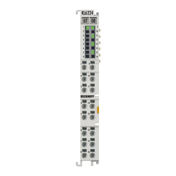
Mounting and wiring Connection Fig. 10: KL6224 connection Connection Terminal point Description Name Input 1 Input 1 + 24 V + 24 V Input 2 Input 2 + 24 V + 24 V Input 3 Input 3 + 24 V + 24 V Input 4 Input 4 + 24 V... -
Page 20: Led Display
K-bus State Ch. 1 - 4 green on / off Status of the signal line (if configured as STD in / out) flashes briefly establishing IO-Link communication twice permanently IO-Link communication established and in operation flashing Version: 2.0.0 KL6224... -
Page 21: Ks2000 Configuration Software
Fieldbus Box modules with the aid of which settings can be modified easily. Alternatively, you have full access to all internal registers of the bus couplers and intelligent terminals. Refer to the register description for the meanings of the registers. KL6224 Version: 2.0.0... - Page 22 • Process values can be specified in the output image for commissioning of the output modules. All possibilities in the online mode can be used in parallel with the actual fieldbus mode of the terminal station. The fieldbus protocol always has the higher priority in this case. Version: 2.0.0 KL6224...
-
Page 23: Configuration Of The Kl6224
In the example shown, this is • a BK9000 Ethernet Coupler • a KL1xx2 Digital Input Terminal • a KL6224 IO-Link terminal • a KL9010 bus end terminal Fig. 13: Display of the fieldbus station in KS2000 The left-hand KS2000 window displays the terminals of the fieldbus station in a tree structure. -
Page 24: Fig. 14 Ks2000 Branches For Channel 1 Of The Kl6224
For the KL6224, the branches Register, Settings and ProcData are displayed: • Register [} 25] permits direct access to the registers of the KL6224. • Dialog boxes for the parameterization of the KL6224 can be found under Settings [} 26]. • ProcData displays the process data of the KL6224. -
Page 25: Register
KS2000 Configuration Software Register You can access the registers of the KL6224 directly under Register. The meaning of the register is explained in the register overview [} 39]. Fig. 15: Register view in KS2000 The screenshot shows the registers of the KL6224. -
Page 26: Settings
Fig. 16: KS2000 - Starting the configuration software Communication channel The communication between KS2000 and the KL6224 can take place either via the fieldbus (via ADS) or via a serial cable (via COM interface). Click on Options/Communication channel to select the communication channel. -
Page 27: Fig. 18 Ks2000 - Display Of The Fieldbus Station
Connect the IO-Link sensor to the KL6224. Switch on the Bus Coupler with the KL6224. Click on Login to connect to the fieldbus station and read the modified KL6224 process image. In the General dialog click on the [Scan devices] button. KL6224... -
Page 28: Fig. 20 Automatic Scan Of The Io-Link Ports
For scanning, the Communication mode must not be set to Communication (Port1/Set- tings). Note Fig. 21: Display of the detected IO-Link devices The detected IO-Link devices are displayed, and the required process data are created. Manual insertion via catalog In the General dialog click on the [Catalog] button. Version: 2.0.0 KL6224... -
Page 29: Fig. 22 Manual Insertion Via Catalog
KS2000 Configuration Software Fig. 22: Manual insertion via catalog Here you can Fig. 23: Calling the create Device dialog use the create Device dialog to manually create an IO-Link device Fig. 24: The create Device dialog KL6224 Version: 2.0.0... -
Page 30: Fig. 25 Import The Device Description
In the General dialog click on the [Import Device Description] button. Fig. 25: Import the device description The XML files for the IO-Link devices are stored in the IO-Link folder of the KS2000 (e.g. under Windows 7 in the folder C:\Program Files (x86)\KS2000_V4\IOLink) Version: 2.0.0 KL6224... -
Page 31: Fig. 26 Selecting The Xml File
Please note: When changing IO-Link devices the following message may occur. Fig. 27: The K-bus interface of the KL6224 has changed This message indicates that the K-bus interface of the KL6224 has changed, because the connection of a further IO-Link device has changed the process image of the KL6224. -
Page 32: Fig. 28 Io-Link Port Settings
An IO-Link device can be operated in different modes. The default mode for IO-Link devices is Communication. Error reaction If this checkbox is checked, the input data are set to 0 in the event of an error. Advanced Click on [Advanced] to open the dialog for the advanced settings. Version: 2.0.0 KL6224... -
Page 33: Fig. 29 Advanced Settings
• V1.1: Data Storage is supported: in delivery state (default) data (sensor parameters) are stored. Process Data Format Here you can adjust the process data format. If the checkbox only Octet String is checked, complex data types (process data) are created as octet string in the interest of simplification. KL6224 Version: 2.0.0... -
Page 34: Access From The User Program
Access from the user program Process image The process image of the KL6224 consists of a 6-byte parameter data block and a 6-, 8-, 18-, 30- or 42-byte process data block. The result is a 12-, 14-, 24-, 36- or 48-byte process image. - Page 35 24-byte process image (default) The 24-byte process image consists of a 6-byte parameter data block and an 18-byte process data block. This setting is enabled in the delivery state of the KL6224. Output data (PLC -> KL6224) Parameter data block (6 bytes) Process data block (18 bytes)
- Page 36 Byte 21 Byte 22 Byte 23 DataOut DataOut DataOut DataOut DataOut DataOut DataOut DataOut DataOut14 DataOut15 DataOut16 DataOut17 Input data (KL6224 -> PLC) Parameter data block (6 bytes) Process data block (18 bytes) Byte 0 Byte 1 Byte 2 Byte 3 Byte 4 Byte 5 Byte 6 Byte 7 Byte 8 Byte 9 Byte 10 Byte 11...
- Page 37 Byte 20 Byte 21 Byte 48 DataOut DataOut DataOut DataOut DataOut DataOut DataOut12 DataOut13 DataOut14 DataOut15 DataOut41 Input data (KL6224 -> PLC) Parameter data block (6 bytes) Process data block (42 bytes) Byte 0 Byte 1 Byte 2 Byte 3 Byte 4 Byte 5 Byte 6 Byte 7 Byte 8 Byte 9 Byte 10 Byte 11 ParaIn0 ParaIn1 ParaIn2 ParaIn3 StatusCh1...
-
Page 38: Control And Status Byte
Number of the register that was read or written. Process data mode Control and status byte in process data mode In process data mode the control and status bytes of the KL6224 currently have no addi- tional function. Note Control byte in process data mode The control byte (CB) is located in the output image [} 34], and is transmitted from the controller to the... -
Page 39: Register Overview
Alignment register R15 [} 40] R16 to R26 reserved 0x0000 reserved 0x0001 SEEROM/RAM R28 to R30 reserved 0x0000 Code word register (not used) 0x0000 R31 [} 40] R32 to R63 Register for displaying the register pages [} 40] [} 45] KL6224 Version: 2.0.0... -
Page 40: Register Description
R15: Alignment register R31: Code word register The code word register of the KL6224 has no function for the user, since all settings that are specified via registers R32 to R63 (register pages) immediately take effect in the KL6224. Register pages In registers R32 to R64 the KL6224 shows the IO-Link configuration, diagnostics and parameterization of the register page [} 45] selected with register R4 [} 40]. -
Page 41: Examples Of Register Communication
• The terminal returns the firmware version 0x3341 in the input data word (byte 1 and byte 2). This is to be interpreted as an ASCII code: ◦ ASCII code 0x33 represents the digit 3 ◦ ASCII code 0x41 represents the letter A The firmware version is thus 3A. KL6224 Version: 2.0.0... -
Page 42: Example 2: Writing To An User Register
Byte 0: Status byte Byte 1: DataIN1, high byte Byte 2: DataIN1, low byte 0x9F (1001 1111 0x12 0x35 Explanation: • The terminal returns the value of the control byte as a receipt in the status byte. Version: 2.0.0 KL6224... - Page 43 • The terminal returns the value of the control byte as a receipt in the status byte. • The terminal returns the current value of the feature register in the input data word (byte 1 and byte 2). KL6224 Version: 2.0.0...
- Page 44 • The terminal returns a value as a receipt in the status byte that differs only in bit 0.6 from the value of the control byte. • The input data word (byte 1 and byte 2) is of no importance after the write access. Any values still displayed are invalid! Version: 2.0.0 KL6224...
-
Page 45: Register Pages For Io-Link Parameters
The parameters of the KL6224 can be accessed via register communication or via the KS2000 [} 21] configuration software. The register model of the terminals is used as a basis. The KL6224 has 64 registers (words). Registers 0 to 31 always have the same meaning. The contents of registers 32 to 63 are specified via the register page selection register (R4 [} 40]). - Page 46 Access from the user program Assignment of the IO-Link parameters to the register page and the terminal register Register page 4 (RP4): Parameter(s) for channel 1 (IO-Link device 1) KL6224 Description Name Comment registers RP4.R32 IO-Link IO-Link DeviceID LowWord Device ID of the IO-Link device master RP4.R33...
- Page 47 Access from the user program KL6224 Description Name Comment registers RP4.R42 IO-Link IO-Link DeviceID LowWord Device ID of the IO-Link device actual data: RP4.R43 IO-Link DeviceID HiWord The actual RP4.R44 IO-Link VendorID LowWord Vendor ID of the IO-Link device data of the RP4.R45...
- Page 48 Register page 6 (RP6): Parameter(s) for channel 3 (IO-Link device 3) Structure like register page 4 [} 46] Register page 7 (RP7): Parameter(s) for channel 4 (IO-Link device 4) Structure like register page 4 [} 46] Register page 8 (RP8): CMD/status interface and acyclic data for IO-Link device KL6224 reg- Description Comment isters Name RP8.R32...
-
Page 49: Accessing Io-Link Parameters
7. Conclude the service by writing TACYCLICKBUSCMD_CMD_ACK to register page 8 R32 (Cmd) Accessing IO-Link parameters The parameters of the KL6224 IO-Link master terminal can be accessed via the parameter data block. Write and read access are documented below, including examples. - Page 50 Therefore the byte sequence 0x68 42 1E 10 03 40 has to be written in the parameter data block for the KL6224. The terminal responds with the following data: Response to write access (KL6224->PLC): parameter data block Byte Byte 0 Byte 1 Byte 2...
- Page 51 Access from the user program Conclusion of read access (PLC->KL6224): parameter data block Byte Byte 0 Byte 1 Byte 2 Byte 3 Byte 4 Byte 5 Name Control byte 0 Control byte 1 ParaOut0 ParaOut1 ParaOut2 ParaOut3 Value 0000 0000 0000 0000 x: The parameter values are not evaluated if the control bytes are 0x00.
-
Page 52: Firmware Version Of The Bus Couplers
Access from the user program Firmware version of the Bus Couplers Required firmware A particular firmware version may be required for operating the KL6224 IO-Link terminal on the Bus Coupler / Bus Terminals Controller (see table [} 53] below) Note In delivery state the KL6224 is set to a process image of 24 bytes. - Page 53 KL6204. *) only if the Bus Coupler is set to complete mapping of the Bus Terminals (e.g. via the KS2000 configuration software). On delivery, these Bus Couplers are set to compact mapping of the Bus Terminals. KL6224 Version: 2.0.0...
-
Page 54: Appendix
Beckhoff's branch offices and representatives Please contact your Beckhoff branch office or representative for local support and service on Beckhoff products! The addresses of Beckhoff's branch offices and representatives round the world can be found on her internet pages: http://www.beckhoff.com You will also find further documentation for Beckhoff components there. - Page 55 Fig. 12 KS2000 configuration software....................Fig. 13 Display of the fieldbus station in KS2000 ..................Fig. 14 KS2000 branches for channel 1 of the KL6224 ................Fig. 15 Register view in KS2000......................Fig. 16 KS2000 - Starting the configuration software ................
Need help?
Do you have a question about the KL6224 and is the answer not in the manual?
Questions and answers