
Subscribe to Our Youtube Channel
Related Manuals for Beckhoff KL2751


Summary of Contents for Beckhoff KL2751
- Page 1 Documentation KL2751/KS2751, KL2761/KS2761 Single channel universal dimmer terminals Version: 3.1.0 Date: 2017-05-29...
-
Page 3: Table Of Contents
1 Foreword .............................. 5 Notes on the documentation...................... 5 Safety instructions .......................... 6 Documentation revision levels ...................... 7 2 Product overview............................ 9 KL2751 - Introduction ........................ 9 KL2761 - Introduction ........................ 10 Basic function principles ....................... 11 Technical data .......................... 12 LED displays.......................... 13 3 Mounting and wiring .......................... 14... - Page 4 Table of contents Version: 3.1.0 KL2751/KS2751, KL2761/KS2761...
-
Page 5: Foreword
The TwinCAT Technology is covered, including but not limited to the following patent applications and patents: EP0851348, US6167425 with corresponding applications or registrations in various other countries. ® EtherCAT is registered trademark and patented technology, licensed by Beckhoff Automation GmbH, Germany Copyright © Beckhoff Automation GmbH & Co. KG, Germany. -
Page 6: Safety Instructions
All the components are supplied in particular hardware and software configurations appropriate for the application. Modifications to hardware or software configurations other than those described in the documentation are not permitted, and nullify the liability of Beckhoff Automation GmbH & Co. KG. Personnel qualification This description is only intended for trained specialists in control, automation and drive engineering who are familiar with the applicable national standards. -
Page 7: Documentation Revision Levels
(refer to the chapter Mounting of terminals with increased thermal power dissipation!) • Output of diagnostic data in the status byte and terminal internal temperature in the data input word DataIN also for KL2751-0000 from firmware 3B 2.4.0 • KS2751 and KS2761 added •... - Page 8 FF - firmware version HH - hardware version Example with ser. no.: 38 06 01 00: 38 - week of production 38 06 - year of production 2006 1C - firmware version 1C 00 - hardware version 00 Version: 3.1.0 KL2751/KS2751, KL2761/KS2761...
-
Page 9: Product Overview
The status of the load can be read in (from firmware version 3B). A variant without power contacts (see contact Diagram, right) is also available in the KL2751-0011 / KS2751-0011. This can be used for 230 V even without a special power feed terminal. -
Page 10: Kl2761 - Introduction
The load status can be read. A variant without power contacts (see contact diagram, right) is also available in the KL2761-0011 / KS2761-0011. This can be used for 230 V even without a special power feed terminal. Version: 3.1.0 KL2751/KS2751, KL2761/KS2761... -
Page 11: Basic Function Principles
Basic function principles Fig. 3: KL2751, KL2761 The KL2751 (300 VA) and KL2761 (600 VA) dimmer terminals are intended for the direct connection of different AC lamp loads. Typical lighting devices such as incandescent lamps, inductive and electronic ballasts are detected and controlled in the right operation mode. In addition to automatic load detection, the Bus Terminal offers a short-circuit-proof and overload-proof output. -
Page 12: Technical Data
Product overview Technical data Technical data KL2751-0000, KS2751-0000, KL2761-0000, KS2761-0000, KL2751-0011, KS2751-0011 KL2761-0011, KS2761-0011 Mains voltage 230 V 230 V Power rating* 300 VA (W), max. 1.35 A 600 VA (W), max. 2.7 A Permissible load types Inductive (transformers only, no ballasts for fluorescent tubes), capacitive or resistive lamp loads... -
Page 13: Led Displays
*) Synchronisation with the mains can only occur if a load is connected! Risk of electric shock! With the Sync LED switched off mains voltage may still be present at the KL2751 output! At this time automatic load detection and synchronisation have not yet been carried out! -
Page 14: Mounting And Wiring
To mount the mounting rails with a height of 7.5 mm under the terminals and couplers, you should use flat mounting connections (e.g. countersunk screws or blind rivets). Version: 3.1.0 KL2751/KS2751, KL2761/KS2761... -
Page 15: Fig. 6 Disassembling Of Terminal
PE power contact The power contact labeled PE can be used as a protective earth. For safety reasons this contact mates first when plugging together, and can ground short-circuit currents of up to 125 A. KL2751/KS2751, KL2761/KS2761 Version: 3.1.0... -
Page 16: Installation Positions
EL/KL terminals to face forward (see Fig. “Recommended distances for standard installation position”). The terminals are ventilated from below, which enables optimum cooling of the electronics through convection. "From below" is relative to the acceleration of gravity. Version: 3.1.0 KL2751/KS2751, KL2761/KS2761... -
Page 17: Fig. 8 Recommended Distances For Standard Installation Position
Other installation positions All other installation positions are characterized by different spatial arrangement of the mounting rail - see Fig “Other installation positions”. The minimum distances to ambient specified above also apply to these installation positions. KL2751/KS2751, KL2761/KS2761 Version: 3.1.0... -
Page 18: Connection System
Standard wiring Fig. 10: Standard wiring The terminals of KLxxxx and ELxxxx series have been tried and tested for years. They feature integrated screwless spring force technology for fast and simple assembly. Version: 3.1.0 KL2751/KS2751, KL2761/KS2761... -
Page 19: Fig. 11 Pluggable Wiring
Ultrasonically “bonded" conductors It is also possible to connect the Standard and High Density Terminals with ultrasonically "bonded" (ultrasonically welded) conductors. In this case, please note the tables concern- Note ing the wire-size width [} 20] below! KL2751/KS2751, KL2761/KS2761 Version: 3.1.0... -
Page 20: Fig. 13 Mounting A Cable On A Terminal Connection
0.14... 0.75 mm Wire size width (single core wires) 0.08 ... 1.5 mm Wire size width (fine-wire conductors) 0.25 ... 1.5 mm Wire size width (ultrasonically “bonded" conductors) only 1.5 mm (see notice [} 19]!) Wire stripping length 8 ... 9 mm Version: 3.1.0 KL2751/KS2751, KL2761/KS2761... -
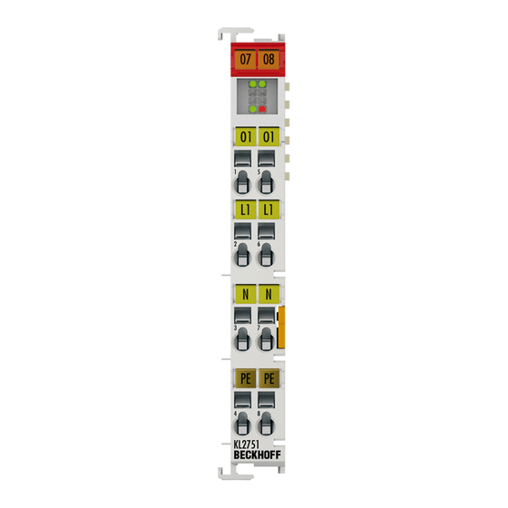
Page 21: Kl2751, Kl2761 - Connection
Risk of injury through electric shock and damage to the device! Bring the Bus Terminals system into a safe, de-energized state before starting mounting, disassembly or wiring of the Bus Terminals! WARNING Fig. 14: Connection taking KL2751 as an example Terminal point No. KL2751-0000, KL2751-0011,... - Page 22 The short circuit current flows for less than 0.5 ms and is switched on automatically. After a short circuit was detected the KL2751 tries to switch the system on again and tests the line with a low voltage. If the short circuit has been eliminated, the dimmer terminal returns to the previous dimmer value.
-
Page 23: Notes On Operation - Intended Use
Notes on operation – intended use Supply • Mains supply No upstream transformers! The KL2751 and KL2761 dimmer terminals are intended for direct operation on mains sup- plies (230 V ) without upstream transformer. Attention Overly large inductances in the supply line to the dimmer terminal will lead to its destruction in the event of a short circuit! Automatic load detection does not operate reliably with an upstream transformer. - Page 24 PLC. This saves the service personnel having to perform the complicated manual initialization when exchanging terminals and also helps to avoid undesirable error states. • Wound transformer with no load on the secondary side Version: 3.1.0 KL2751/KS2751, KL2761/KS2761...
- Page 25 This effect leads to premature ageing of the lamp. You can counteract this premature ageing by setting a flatter dimming ramp. *) The ballast must be connected between the dimmer terminal and the halogen lamp (see mains supply [} 23])! KL2751/KS2751, KL2761/KS2761 Version: 3.1.0...
-
Page 26: Application Examples - Overview
24 V and would be destroyed if 230 V is applied at their power contacts! The example shows the control of an incandescent lamp by a KL2751-0000. The mains voltage (230 V ) is fed to the power contacts via the KL9160 power feed terminal. -
Page 27: Kl2751-0011 - Application Example
The supply in of mains voltage without a power feed terminal is permissible only for dimmer terminals without power contacts: Attention KL2751-0011, KL2761-0011, KS2751-0011, KS2761-0011 The example shows the control of an incandescent lamp by a KL2751-0011. The mains voltage (230 V ) is fed directly to the KL2751-0011. Fig. 16: KL2751-0011 - Application example KL2751/KS2751, KL2761/KS2761... -
Page 28: Configuration Software Ks2000
Fieldbus Box modules with the aid of which settings can be modified easily. Alternatively, you have full access to all internal registers of the bus couplers and intelligent terminals. Refer to the register description for the meanings of the registers. Version: 3.1.0 KL2751/KS2751, KL2761/KS2761... - Page 29 • Process values can be specified in the output image for commissioning of the output modules. All possibilities in the online mode can be used in parallel with the actual fieldbus mode of the terminal station. The fieldbus protocol always has the higher priority in this case. KL2751/KS2751, KL2761/KS2761 Version: 3.1.0...
-
Page 30: Parameterization With Ks2000
In the sample shown, this is • a BK9000 Bus Coupler for Ethernet • a KL9160 power feed terminal for 230 V with diagnostics • a KL2751 dimmer terminal • a KL9010 bus end terminal Fig. 18: Display of the fieldbus station in KS2000 The left-hand KS2000 window displays the terminals of the fieldbus station in a tree structure. -
Page 31: Fig. 19 Ks2000 Tree Branches For Channel 1 Of The Kl2535
Fig. 19: KS2000 tree branches for channel 1 of the KL2535 For the KL5151, the branches Register, Settings and ProcData are displayed: • Register [} 32] permits direct access to the registers of the KL2751. • Under Settings [} 33] you find dialog boxes for parameterization the KL2751. -
Page 32: Register
Under Register you can directly access the registers of the dimmer terminal. The meaning of the register is explained in the register overview [} 41]. The following picture shows the registers of the KL2751. Fig. 20: Register view in KS2000 Version: 3.1.0... -
Page 33: Settings
Configuration software KS2000 Settings The dialog mask for the parameterization of the KL2751/KL2761 can be found under Settings. Fig. 21: Settings via KS2000 Operating mode • Watchdog timer active (R32.2 [} 43]) Here you can deactivate the watchdog (default: active). • Watchdog timer active (R32.2 [} 43]) Here you can activate user scaling (default: inactive). - Page 34 ◦ Rectifier, positive: only the positive half-wave is switched through to the load with leading edge phase control Do not use this operation mode with firmware version 2E [} 7] of the KL2751 or with firmware version 1E [} 7] of the KL2761! Instead, use the operation mode Rectifier mode, negative with these firmware versions! ◦...
-
Page 35: Process Data
Only modify these initial values if you are certain that the state of your equipment permits it, and that there will be no risk to people or to the machine! After pressing the Settings button you can set the format of the numerical display to hexadecimal, decimal or binary. KL2751/KS2751, KL2761/KS2761 Version: 3.1.0... -
Page 36: Fig. 26 Setting The Display
Configuration software KS2000 Fig. 26: Setting the display Version: 3.1.0 KL2751/KS2751, KL2761/KS2761... -
Page 37: Access From The User Program
Access from the user program Access from the user program Process image The KL2751 and KL2761 appear in the complex process image with 3 bytes of input data and 3 bytes of output data. These are organized as follows: Byte offset (with-... -
Page 38: Control And Status Bytes With Diagnosis
Access from the user program Control and status bytes with diagnosis This description applies to • KL2751-0000 / KS2751-0000 with firmware versions 3B or higher • KL2751-0011 / KS2751-0011 with firmware versions 3B or higher • KL2761-0000 / KS2761-0000 • KL2761-0011 / KS2761-0011 Process data mode Control byte (for process data mode) The control byte (CB) is located in the output image [} 37], and is transmitted from the controller to the... - Page 39 SB1.4 SB1.3 SB1.2 SB1.1 SB1.0 Name RegAccess R/W Reg. no. Legend Name Description SB1.7 RegAccess Acknowledgement for register access SB1.6 R Read access SB1.5 Reg. no. Number of the register that was read or written. SB1.0 KL2751/KS2751, KL2761/KS2761 Version: 3.1.0...
-
Page 40: Control And Status Bytes Without Diagnosis
Access from the user program Control and status bytes without diagnosis This description applies to • KL2751-0000 / KS2751-0000 with firmware versions lower than 3B • KL2751-0011 / KS2751-0011 with firmware versions lower than 3B Process data mode Control and status byte have no functionality in process data mode. -
Page 41: Register Overview
The registers are used for the parameterization of the dimmer terminal. They can be read or written by means of register communication. Register no. Comment Default value Memory reserved reserved Command register 0x0000 R7 [} 42] Terminal type KL2751-0000 0x0ABF 2751 R8 [} 42] KL2751-0011 KL2761-0000 0x0AC9 2761 KL2761-0011 Firmware version e.g. 0x3141 e.g. 1A R9 [} 42]... -
Page 42: Register Description
R41: 0 (KL2751-0000, KL2751-0011, KL2761-0000, KL2761-0011) R8: Terminal type The terminal identifier is contained in register R8: KL2751 or KL2761. R9: Firmware version Register R9 contains the ASCII coding of the terminal's firmware version, e.g. 0x3141 = '1A'. The '0x31' corresponds here to the ASCII character '1', while the '0x41' represents the ASCII character 'A'. - Page 43 • to execute the current brightness change (when R32.3 = 1 : 50 ms : 100 ms : 200 ms : 500 ms (default) : 1 s : 2 s : 5 s : 10 s R36: Watchdog Timeout This register specifies the timeout in the event of a fieldbus error. The unit is 10 ms (default: 10 = 100 ms). KL2751/KS2751, KL2761/KS2761 Version: 3.1.0...
- Page 44 : Leading edge phase control : Rectifier mode, positive (positive half-wave with leading edge phase control) Do not use this operation mode with firmware version [} 7] 2E of the KL2751 or with firmware version [} 7] 1E of the KL2761! Instead, use the operation mode Rectifier mode, negative with these firmware versions! : Rectifier mode, negative (negative half-wave with leading edge phase control)
-
Page 45: Examples Of Register Communication
0xDF (1101 1111 0x12 0x35 Explanation: • Bit 0.7 set means: Register communication switched on. • Bit 0.6 set means: writing to the register. • Bits 0.5 to 0.0 specify the register number 31 with 01 1111 KL2751/KS2751, KL2761/KS2761 Version: 3.1.0... - Page 46 CAUTION nal. Refer to the description of the feature register of your terminal (chapter Register de- scription) regarding the meaning of the individual bits before changing the values. Version: 3.1.0 KL2751/KS2751, KL2761/KS2761...
- Page 47 • The terminal returns a value as a receipt in the status byte that differs only in bit 0.6 from the value of the control byte. • The input data word (byte 1 and byte 2) is of no importance after the write access. Any values still displayed are invalid! KL2751/KS2751, KL2761/KS2761 Version: 3.1.0...
-
Page 48: Twincat
The general use of hardware and software from the open PC world requires some checking: Unsuitable components can upset the PC system. Beckhoff integrates a handy display of the real-time jitter in order to provide administrators with a simple means of evaluating hardware and software. A system message during operation can draw attention to error states. - Page 49 According to the requirement for operating resources, the TwinCAT software devices can be distributed: TwinCAT PLC programs can be executed on PCs and on Beckhoff Bus Terminal controllers. A "message router" manages and distributes all the messages, both in the system and via TCP/IP connections. PC systems can be connected to one another by TCP/IP;...
-
Page 50: Programming
TwinCAT 3: TwinCAT 3 PLC Lib: Tc2_IoFunctions FB_KL27x1Config function block The KL2751 and KL2761 terminals can be configured using the FB-KL27x1Config function block. A detailed description can be found in the Beckhoff Information System: TwinCAT2: TwinCAT PLC Lib: IO functions/Bus Terminal configuration... -
Page 51: Importing A Function Block
The import of a function block into your TwinCAT system is described in the chapter Im- porting a function block [} 51]. Note Importing a function block To import a function block into your TwinCAT, click on the menu item Project/Import in the TwinCAT PLC Control. KL2751/KS2751, KL2761/KS2761 Version: 3.1.0... -
Page 52: Fig. 28 Importing A Function Block Into Twincat Plc
Select the folder in which you have saved the exp file (DB_Dimmer1SwitchEco.exp in the example), select the file and click on the Open button. Fig. 29: Import Project dialog Following successful import the PC Control reports Import complete. Version: 3.1.0 KL2751/KS2751, KL2761/KS2761... -
Page 53: Appendix
Beckhoff's branch offices and representatives Please contact your Beckhoff branch office or representative for local support and service on Beckhoff products! The addresses of Beckhoff's branch offices and representatives round the world can be found on her internet pages: http://www.beckhoff.com You will also find further documentation for Beckhoff components there. - Page 54 Pluggable wiring .......................... Fig. 12 High Density Terminals........................ Fig. 13 Mounting a cable on a terminal connection ................. Fig. 14 Connection taking KL2751 as an example .................. Fig. 15 KL2751-0000 connection example ....................Fig. 16 KL2751-0011 - Application example.................... Fig. 17 KS2000 configuration software....................
Need help?
Do you have a question about the KL2751 and is the answer not in the manual?
Questions and answers