Table of Contents
Advertisement
Quick Links
Advertisement
Table of Contents
Troubleshooting

Subscribe to Our Youtube Channel
Related Manuals for Pro-Cut X9


Summary of Contents for Pro-Cut X9
- Page 1 TECHNICAL MANUAL WWW.PROCUTUSA.COM PG /...
- Page 3 TECHNICAL MANUAL P · 800.543.6618 F · 603.298.8404 info@procutusa.com www.procutusa.com...
- Page 4 OUR MISSION Pro-Cut International is dedicated to providing our customers with the most advanced, precise, and profitable tools for brake repair. We have worked with, learned from and solved problems for people at all levels of the brake repair business - from the largest auto manufacturers and national service chains to one-bay, one-man operations.
- Page 5 For the period of two (2) years from the original date of purchase, if we determine that the equipment is defective subject to the limitations of this warranty, we will replace it at no charge for labor. Pro-Cut International warrants any such work done against defects in materials or workmanship for the remaining portion of the original warranty period.
-
Page 6: Table Of Contents
Pro-Cut Mission 50-1148 Gage Pick Up Module Safety and Warning Information G2X Calibration Introduction G2X Troubleshooting Lateral Run-out Defined X9 Lathe Overview GYR Technical Supplement Lathe Setup GYR Component Overview Vehicle Preparation Setting up your GYR Lathe Preparation: Checking Cutting Tips... - Page 7 IMPORTANT SAFETY INSTRUCTIONS The X9 Rotor Matching System is a precision instrument which requires close attention while in operation. It will pro- vide many years of service if it is operated safely. Basic Safety precautions should always be followed, including the...
-
Page 8: Introduction
INTRODUCTION WELCOME TO THE PRO-CUT TEAM. Congratulations on your purchase of the PFM X9, the world’s fastest and most accurate computerized on-car brake lathe. For many years, on-car lathes were used only for rotors that were difficult to remove. Due to current trends, virtually all auto manufacturers now require or recommend the use of on-car technology to match every rotor to every hub. - Page 9 YOUR LATHE PACKAGE Every Pro-Cut PFM X9 Lathe Package comes complete, ready to assemble and use. Setup and on-site training is included by a local, certified Pro-Cut Rep. Please contact Pro-Cut at 800-543-6618 immediately if you have not already made arrangements for on-site training. In order for your shop to appreciate the benefits of this machine as soon as possible after the lathe is installed, it is CRITICAL that technicians take the on-line training PRIOR to the Pro-Cut Rep arriving to set up the lathe.
- Page 10 Run-out DEFINED LATERAL Run-out leads to ... THICKNESS VARIATION which results in ... BRAKE PEDAL PULSATION. PG / 800.543.6618...
- Page 11 Most manufacturers require rotor run-out to be below 0.002”. The X9 Rotor Matching System allows you to match every rotor to the hub on which it turns. The on-board PFM computer compensation system delivers a precise alignment between the lathe axis and the hub axis, thereby guaranteeing that a Pro-Cut machined rotor will have less than 0.001”...
- Page 12 Lathe Overview PG / 800.543.6618...
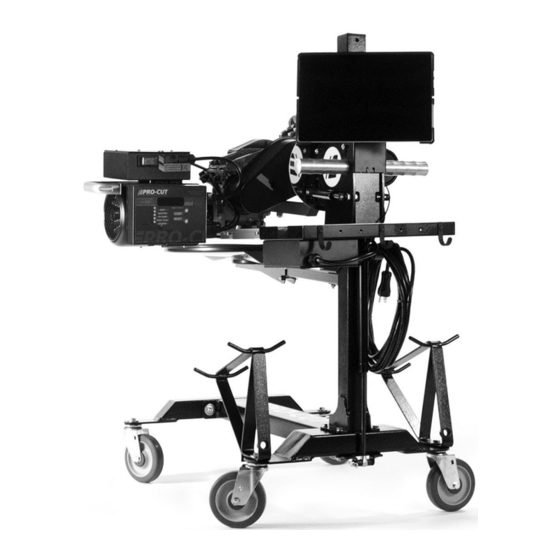
- Page 13 COMPONENTS X9 Computer Box Automatic Shut-off Cam On/Off Switch Cut Depth Adjustment Dials 1 hp Motor Cutting Tips/Inserts Draw Bar Knob Tool Arm Lock Lever Adjustment Flange (obscured) Trolley Adjustment Solenoid Cutting Head lateral Lock Knob Feed Engagement Knob Lathe Trolley Arm...
- Page 14 SETTING UP A NEW LATHE Before you begin setting up, check contents against the parts diagram enclosed in the lathe package. If you are missing any parts, call Pro-Cut immediately. PG / 800.543.6618...
- Page 15 Cutting ASSEMBLE THE TROLLEY Open the trolley box and check contents against the parts diagram . If you are missing any parts, call Pro-Cut immediately. Proceed with assembly, following the instructions enclosed in the box. Edge MOUNT THE LATHE TO THE TROLLEY Once the trolley is assembled you will need to mount the lathe to the trolley.
-
Page 16: Vehicle Preparation
CV joints using the yellow S-hooks provided (pn 37-034). Be sure to remove all wheels that may turn when the lathe is turned on. 4. Use Pro-Cut part number 37-996 wheel hub cleaning kit, or other suitable wheel hub cleaning tool to remove rust or debris. Clean all material from the mounting area. - Page 17 NOTE It is important to start on the proper side. The Pro-Cut mounts directly to the hub of the vehicle. With the lathe right-side up (FIG:1) the cutting head is to the right of the hub as you face the vehicle wheel well.
-
Page 18: Lathe Preparation: Checking Cutting Tips
Before mounting the lathe, check the cutting tips and make sure they are ready for use. The cutting tips are one of the most critical components of the machine. It is vital that they are Pro-Cut brand tips in good condition and properly mounted. Each cutting tip has three corners which may be used. -
Page 19: Step 1: Mount The Adapter
Step 4: Make the Cut (3-4 mins.) steel like wheels. They are not designed to withstand If the four steps are followed properly on each brake job, the Pro-Cut X9 RMS will operate accurately and efficiently. the use of impact tools. DO NOT USE IMPACT... - Page 20 MACHINING ROTORS CONTINUED STEP 2: SET UP THE LATHE (2 Minutes) A. Mount the Lathe to the Adapter Move the cutting head out so that the tips will not strike the rotor as you mount the lathe. Next, roll the machine into place and match it up with the adapter. Note that the trolley moves up and down to accommodate different heights.
-
Page 21: Step 2: Set Up The Lathe
NOTE: The Pro-Cut will mount cutting head up on one side and cutting head down on the other. Always start right-side up; this way, when you proceed to the other side of the vehicle, the offset of the cutting head, and the shut-off cam will already be set. -
Page 22: Step 3: Adjust For Lateral Run-Out
You must adjust for lateral run-out to eliminate wobble (run-out) from the machine before cutting. This procedure en- sures the resulting machined rotor will have minimal run-out after cutting. The PFM X9 Rotor Matching System has been calibrated to reduce run-out to less than 0.001” [25.4 micron] or less as measured on the rotor face. - Page 23 MACHINING ROTORS STEP 3: ADJUST FOR LATERAL Run-out CONTINUED (1 Minute) If the TRY AGAIN light is illuminated, the machine is unable to fully adjust for run-out. This dif- NOTE ficulty could be due to looseness of fittings, irregular run-out, damage to wheel bearings or other components, or other factors relating to set-up.
-
Page 24: Step 4: Make The Cut
MACHINING ROTORS Step 4: MAKE THE CUT (4 Minutes) With the motor still running, loosen the forward lock lever on the cutting head to allow cutting depth adjustment. Turn cut-depth knobs counter-clockwise until the tips can clear both sides of the rotor. Crank the cutting head in to 1/2"... - Page 25 MACHINING ROTORS Step 4: MAKE THE CUT (4 Minutes) CONTINUED Now that you have adjusted for depth, tighten the forward lock lever (over the tool arms). This lever must be tight to minimize vibration. For safety, it is advised at this time that you turn the motor off. Place the chip deflector/silencer around the rotor and over the cutting tips.
- Page 26 Cleaning the rotor surface after machining to remove all dust and debris is very important in the overall quality of the brake job. Pro-Cut recommends using liberal amounts of warm water with a mild detergent and drying thoroughly with clean towels to be certain all loose material is removed.
-
Page 27: Machining The Opposite Side
MACHINING ROTORS MACHINING THE OPPOSITE SIDE Loosen the trolley disc lock lever and rotate the machine into the upside-down position. NOTE The procedure for cutting in the upside-down position is the same, though fewer steps are needed as the lateral position of the cutting head relative to the rotor is already set. The lathe mounts in the same Be sure the auto shut-off manner. -
Page 28: Vehicle Reassembly
Special care should be used in making sure that ABS sensors are free of debris. Reassemble the brakes and wheels to the manufacturer’s specifications. HELPFUL HINTS FOR CUTTING ROTORS USING A PRO-CUT LATHE · Inspect cutting tip edge for wear and damage. -
Page 29: Maintenance
MAINTENANCE The Pro-Cut lathe is simple and rugged. With just a few maintenance tips you can ensure a long and profitable life for your machine. Check cutting tip edges. If there are chips or dings, turn or replace the tip. Be sure they are right-side up so that the groove and dots are visible. -
Page 30: Troubleshooting Assuring A Smooth Finish
NOTE Brake performance is dependent upon rotor surface finish as well as minimizing lateral run-out. The Pro-Cut lathe is designed to give you a superior surface finish on any rotor as long as proper maintenance is followed. The Pro-Cut X9 should pro-... - Page 31 The chip deflector must be used on every cut to ensure proper finish. New chip deflectors can be purchased directly from Pro-Cut. The chip deflector reduces vibration and must be used on EVERY cut.
- Page 32 50-1650 SLIDE PLATE RESISTANCE ADJUSTMENT AND FEED SCREW ADJUSTMENT Slide Plate Resistance Adjustment Remove the Cutting Head from the Slide Plate. Center the Slide Plate on the Gear Box between the screws that are through the dove tail plate. Locate and loosen the 2 wedge locating screws on the slide plate. Be sure that the runners of the slide plate are clean and free of debris.
- Page 33 CALIBRATION PROCEDURE The Pro-Cut PFM X9 Rotor Matching System is calibrated with an acceptance number from the factory. Normally, this will never need to be changed. Please call Pro-Cut Service Department before attempting calibration procedure to confirm that this is the problem.
- Page 34 DRO COMPENSATION INSTRUCTIONS Your new PFM X9 On-Vehicle Lathe is equipped with DRO. DRO, which stands for "Digital Run Out," combines several features to offer you increased accuracy as well as lathe diagnostics and efficiency tracking. By checking these values on a monthly basis, managers can track their ROI based on the machine usage.
- Page 35 DRO EFFICIENCY TRACKING The remaining screens are accessed through the START button and are scrolled through by continued pressing of the START button. The machine first must be in the Ready mode and the motor must be off. Press and hold the START button until all of the lights come on, then release and the Hour screen will be displayed .
- Page 36 DRO EFFICIENCY TRACKING Press the START button again and the word "Total" will be displayed. Press the START button once more and the total number of times the machine has compensated will be displayed. This value represents the total num- ber of completed compensation cy- cles.
- Page 37 DRO DIAGNOSTICS CONTINUED Press the START button again and the word "5 Adj." screen will be displayed. Press the START button once more and the last five adjustment cycle times will be displayed in seconds. Press the START button once more and you will reach the units display toggle. Pressing the 'calibration button' will toggle between inch and metric (mm for thickness and microns for runout) display modes.
-
Page 38: G2X Technical Supplement
G2X TECHNICAL SUPPLEMENT PG / 800.543.6618... - Page 39 YOUR LATHE PACKAGE The G2X upgrade package allows for live display of rotor thickness on the DRO screen. The 50- 1250 Lateral cutting head replaces the 50-220 cutting head. This new cutting head allows us to use a single sensor to measure the distance between the arms, and thus the distance between the carbide insert tips.
- Page 40 G2X Overview PG / 800.543.6618...
- Page 41 G2X COMPONENTS With 50-1250 Cutting Head Position lock lever Rotor centering pointer Adjustment dial - inboard Throat depth lock screws Adjustment dial - outboard Slide Sensor Assembly Tool arm position lock knobs Carbide cutting inserts WWW.PROCUTUSA.COM PG /...
- Page 42 THE 50-1250 CUTTING HEAD Unlike Pro-Cut's earlier designs, this cutting head's arms move from side to side. The adjustment knobs face the user. The depth adjustment dials are offset; as a reminder - the one nearest you (AA) adjusts the outboard (away from vehicle) depth of cut and the one farther from you (BB) adjusts the inboard (nearest to vehicle) depth of cut.
-
Page 43: 50-1250 Cutting Head
NOTE: Use only Pro-Cut Cutting Tips (50-742 or 50-743). Although other tips will fit the machine, only Pro-Cut tips have been specifically engineered in tandem with the Pro-Cut lathe. Using a non-Pro-Cut tip may compromise lathe performance and result in poor surface finish. - Page 44 USING THE 50-1250 CUTTING HEAD CONTINUED If a rotor has an extra wide face width, or if the inboard face is wider than the outboard face, the inserts may be adjusted to allow for staggered cheeks by loosening the throat depth lock screws, moving the insert holder to the desired position and then re-tightening the throat depth lock screws.
- Page 45 THE SLIDE SENSOR 50-1206 THE SLIDE SENSOR is an absolute encoder device, nearly identical to those used in digital calipers. When mounted to a correctly adjusted cutting head and properly calibrated it should give an accuracy of +/-.004" [0.102 mm]. The sensor itself is enclosed in a case to prevent dust contamination.
- Page 46 THE GAUGE PICK UP MODULE 50-1148 The Gauge Pickup module has two jobs. It decodes the data from the slide sensor (aka the gauge) and sends it to the main lathe computer for display. When used in a full GYR package, it also detects when a cut is being made (the pickup).
- Page 47 THE GAUGE PICK UP MODULE 50-1148 ASSEMBLY Remove the cover on the bottom of the bevel gearbox assembly. Replace it with the 50-1148 assembly, taking care to aim the eight pin connector towards the lathe body. With the lathe unplugged from AC power, seat the 6 pin connector from the slide sensor, and the 8 pin connector from the lathe's harness.
-
Page 48: G2X Calibration
G2X CALIBRATION Before the lathe may be used to cut rotors, the slide scale and cutting head assembly must be calibrated. This calibration procedure should be perfomed at least monthly, or any time the slide scale is removed from the cutting head. It is not necessary to re-calibrate every time an insert is rotated, the inserts are very precise and do not vary much. - Page 49 G2X CALIBRATION CONTINUED CALIBRATION STEP 3: With the display in 'H' mode, and the 0.800" / 20.32mm thick calibration block in place, press the CALI- BRATION button, the same one used to set the LRO Acceptance number. You will hear a beep. When you have done this, you can press the Reset button to exit the H mode or use the Start button again if you wish to read the DRO numbers out or switch between inch and mm display mode.
- Page 50 G2X SERVICE CONSIDERATIONS A properly set up and adjusted 50-1250 cutting head will provide smooth yet firm arm motion with minimal knob backlash. If you are having difficulty turning the dials when the arm knobs are backed off, or if the dials turn very easily then adjustments need to be made to the assembly.
-
Page 51: G2X Troubleshooting
G2X TROUBLE SHOOTING No Thickness Measurement Data. ISSUE TROUBLESHOOT One of the white rectangular cables connect to the device under the feed mechanism are partially or not fully connected. To solve this: Power off the lathe by unplugging it. Re-seat these cables firmly. Power the lathe on. -
Page 52: Gyr Technical Supplement
GYR TECHNICAL SUPPLEMENT PG / 800.543.6618... - Page 53 Before GYR, in order to perform the perfect brake job, you needed a brake specification guide, a dial indicator, a rotor micrometer, and a Pro-Cut Lathe to give a great finish and eliminate lateral run out. Now all of those capabilities are integrated into one, easy to use system, and now brake service will never be the same again! WWW.PROCUTUSA.COM...
- Page 54 This section of the manual only covers the GYR specific components. Once your IT department has followed the IT set up procedures, and your local Pro-Cut Representative has installed all the GYR components, you’re ready to do your first brake job! GYR SPECIFIC COMPONENTS...
- Page 55 WWW.PROCUTUSA.COM PG /...
-
Page 56: Setting Up Your Gyr
SETTING UP YOUR GYR The GYR uses a web based data collection site, so you will need to have wireless internet access to best utilize the system's many features. Please follow the following IT set up instructions to prepare for proper installation of your new GYR system. - Page 57 OPTIONAL - The GYR Tablet comes with Windows 7 Professional which can be placed on the local domain. - Pro-Cut offers technical support through “Log Me In - Rescue,” which allows Pro-Cut Service limited access to local computer networks. FOR TECH SUPPORT, CALL 800.543.6618. PRESS #2 FOR SERVICE.
- Page 58 SERVICE CORRIDOR CONCEPT Once the GYR components are set up and tested, you’re ready to begin the brake service. The steps are simple, sequential, and the program will guide you through the process giving you help along the way. We call this the service corridor.
- Page 59 SERVICE CORRIDOR CONCEPT CONTINUED LEFT-REAR Wheel selected with LRO / TK specs displayed on screen» SCREEN Follow the instructions given on the yellow command bar in the center of the screen. Select the proper adapter and attach to the vehicle’s hub; The part number of the correct adapter will be displayed.
- Page 60 SERVICE CORRIDOR CONCEPT CONTINUED Turn the lathe motor on and adjust for lateral run-out by touching the green “Begin LRO Adjust” button on the touch screen. NOTE: LRO Adjustment in Process Once the lateral run-out is corrected “LRO Adjust Complete” will be displayed in the yellow command bar, and the actual LRO will be displayed as well.
- Page 61 'Failed'. A cut must be made to help prevent the use of the Pro-Cut Gyr as a tool for fraudulent 'rotor was too thin to machine' OEM warranty claims. A cut rotor allows for physical audit by OEMs for brake warranty claims. If we did not require the cut, the tool arms could be set to any width and the customer or OEM presented with (false) information that their rotor was too thin to cut.
- Page 62 SERVICE CORRIDOR CONCEPT CONTINUED During the cut, the GPM (gage pick-up module) unit mounted under the cutting head gear box listens for the cut and will cause the “Cut in Progress” alert to be displayed in the yellow command bar. Once the cutting tips clear the rotor and the cut is complete the “Cut Completed”...
- Page 63 Once the first side is complete, move to the other side and complete the second rotor on that axle. You will need to rotate the lathe 180 degrees as per the instructions in the lathe owner’s manual. Follow the same process for the second rotor, scratching the rotor, marking the beginning thickness, cutting to the appropriate depth, and saving the results.
- Page 64 MORE FEATURES CUTTING TIP LIFE MANAGEMENT The GYR is also equipped with a tip management application that can help you control expenses by making certain that each tip is completely used. Simply touch the Cutting Tip icon when you change or rotate tips to keep track of their usage and you will be alerted when to change by the flashing tip count icon.
-
Page 65: Customer Vehicle And Management Reports
'Print Report Card'. This will let you choose the time period, income and expense values to estimate profits created by using the Pro-Cut Gyr lathe. Once in this screen you can review the details of all the brake work you have performed by job, and also generate manage- ment reports. - Page 66 TROUBLESHOOTING AND CALIBRATION GYR is a fast, automated rotor matching system for making in-spec brake repairs while capturing rotor thickness and runout metrics. However, things can go wrong; mistakes can be made. The following troubleshooting guide will help you diagnose issues before you give us a call.
- Page 67 GYR TROUBLESHOOTING GUIDE LATHE/PC will not communicate. Screen lower left reads “Disconnected.” Motor does turn on. ISSUE TROUBLESHOOT 1. CHECK ALL WIRING CONNECTIONS. After making sure all are connected, cycle the AC power to the lathe by unplugging it from the wall and plugging it in again. 2.
- Page 68 GYR TROUBLESHOOTING GUIDE CONTINUED PC will not print. ISSUE Check Wi-Fi connectivity. Any network issues should be reported to your internal IT TROUBLESHOOT department. Thickness value of rotor does not change on screen. ISSUE TROUBLESHOOT 1. Check wire connections on cutting head sensor. 2.
- Page 69 CALIBRATION GUIDE Motor must be off but unit plugged in. ATTENTION Computer must be on. Install fresh unused cutting tips on the cutting arms. A .8” calibration Select “i” on screen. block is required Select “Calibrate lathe.” to perform this Properly place the 0.800"...
- Page 70 ADAPTERS ADAPTER PACKAGES 50-687 50-688 50-693 50-946 5-LUG ADAPTER - LARGE 4-HOLE ADAPTER 5-HOLE ADAPTER LIGHT DUTY 6 LUG ADAPTER Fits most 4-lug vehicles. Fits most smaller 5-lug Fits larger 5 lug cars and smaller SUVs 6 lug adapter fits newer Colorado/Can- and trucks such as Toyota Camry, most vehicles.
- Page 71 50-694 50-683 50-935 50-681 TALL HUB TRUCK ADAPTER 3/4 TON TRUCK ADAPTER/COMMON DUAL WHEEL TRUCK TOYOTA SPECIALTY & ALTERNATE ADAPTER Primarily used to fit the 2003+ Fits most 3/4 ton single wheel trucks TRUCK ADAPTER Expedition and 2004+F150, front and rear. Fits 1-ton Ford, Dodge, and Fits most pickups and SUVs including the Toyota Land Cruiser and VW Touareg (does...
- Page 72 ITEM PART QTY. NUMBER 50-2201 50-2202 50-1831 X9 PARTS DIAGRAM 50-2200 X9 LATHE BODY 50-2218 50-566 ITEM PART 50-570 QTY. NUMBER 50-565 50-2201 50-1400 50-2202 50-1831 50-1804 50-2218 50-1184 50-566 50-570 50-2220 50-565 50-1650 50-1400 50-1804 50-1824 50-1184 50-2211 50-2220...
- Page 73 X9 PARTS DIAGRAM 50-220 CUTTING HEAD ITEM PART QTY. NUMBER 50-293 50-373 50-374 37-077 50-252 Assembly: 50-053 50-260 37-473 50-253 50-254 10 50-249 11 37-812 12 50-098 13 36-010 14 37-077 15 35-259 16 36-002 17 37-082 18 37-003 19 50-365 20 50-364 WWW.PROCUTUSA.COM...
- Page 74 ITEM Part Number QTY. X9 PARTS DIAGRAM PART NO. 50-1650 50-1660 50-1673 ITEM Part Number QTY. 37-114 50-1660 36-002 50-1673 35-236 37-114 36-002 50-1652 35-236 37-056 50-1652 50-016 37-056 50-1668 50-016 50-1668 37-057 37-057 35-927 35-927 50-018 50-018 35-926 35-926...
- Page 75 29 25 ITEM PART X9 PARTS DIAGRAM PRO-CUT 50-2195 TROLLEY QTY. NUMBER 50-2047 50-2048 50-2029 37-038 50-2019 50-2030 50-2073.1 37-304 37-305 50-2072.1 16 18 37-064 50-2071 50-2076 50-2016 50-2074 50-2075 37-485 50-1032 37-721 35-239 37-498 36-001B 50-2077 50-2078 50-1061 50-1062...
- Page 76 X9 PARTS DIAGRAM PART NO. 50-1648 ITEM NO. Part Number QTY. 50-1155 50-1127 35-258 50-1669 FOLD OVER BEFORE ASSEMBLY PG / 800.543.6618...
- Page 77 X9 PARTS DIAGRAM PART NO. 50-1190 50-1190 ITEM PART NUMBER QTY. 50-457 35-806 35-311 37-016 35-802 50-1135 50-1128 50-1125 37-628 10 50-1154 11 50-1144 12 35-418 WWW.PROCUTUSA.COM PG /...
- Page 78 X9 PARTS DIAGRAM PART NO. 50-1250 (G2X / GYR PACKAGE) ITEM Part Number QTY. ITEM Part Number QTY. 50-1211 50-1228 50-1211 35-257 50-1228 35-284 35-257 35-284 50-1256 50-1256 50-1259 50-1259 50-1261 50-1261 50-1254 50-1254 37-076 38 40 38 40 37-076...
- Page 79 ITEM Part Number QTY. 50-1145 50-1146 50-1221 50-1244 X9 PARTS DIAGRAM PART NO. 50-1206 50-1239 ITEM 50-1242 (G2X / GYR PACKAGE) Part Number QTY. 50-1243 50-1145 50-1240 50-1146 35-303 50-1221 35-270 50-1244 35-295 50-1239 36-023 50-1242 37-019 50-1243 35-322 50-1240...
- Page 80 ITEM PART X9 PARTS DIAGRAM PART NO. 50-2202 QTY. NUMBER 37-2200 35-364 50-546 37-813 35-289 50-2207 37-003 36-002 35-320 36-173 35-317 50-1834 35-717 50-2209 35-236 50-2243 50-2244 PG / 800.543.6618...
- Page 81 X9 PARTS DIAGRAM PART NO. 50-1390 (GYR PACKAGE) ITEM NO. PART NUMBER QTY. 37-1390 50-2066 37-026 37-090 37-1111 35-161 37-1842 36-001A 50-1358 36-002 37-003 35-238 WWW.PROCUTUSA.COM PG /...
-
Page 82: Maintenance Schedule
MAINTENANCE SCHEDULE DATE NOTES DRO READINGS MONTH / DAY / YEAR | HOURS | TOTAL | AVERAGE | LAST 5 | PG / 800.543.6618... - Page 83 MAINTENANCE SCHEDULE DATE NOTES DRO READINGS MONTH / DAY / YEAR | HOURS | TOTAL | AVERAGE | LAST 5 | WWW.PROCUTUSA.COM PG /...
- Page 84 50-761 PRINTED WITH PRIDE IN THE U.S.A. Pro-Cut International, LLC 10 Technology Drive #4 West Lebanon, NH 03784 P. 800.543.6618 / 603.298.5200 Global inquiries please see: F. 603.298.8404 R4/2021 © PRO-CUT INTERNATIONAL, LLC www.procutusa.com E. info@procutusa.com...
Need help?
Do you have a question about the X9 and is the answer not in the manual?
Questions and answers