Advertisement
Quick Links
Advertisement

Related Manuals for Pro-Cut B17


Summary of Contents for Pro-Cut B17
- Page 1 TECHNICAL MANUAL...
- Page 5 TECHNICAL MANUAL P · 800.543.6618 F · 603.298.8404 info@procutusa.com www.procutusa.com...
-
Page 6: Table Of Contents
Operations Procedures Diagrams Multi-Speed Settings Maintenance Schedule Set Up for Rotors or Drum Cutting *NOTE: When service or replacement parts are required, please contact your local Pro-Cut Representative through either the SuperTech app or through our website: www.procutusa.com PG / 800.543.6618... - Page 7 OUR MISSION Pro-Cut International is dedicated to providing our customers with the most advanced, precise, and profitable tools for brake repair. We have worked with, learned from and solved problems for people at all levels of the brake repair business - from the largest auto manufacturers and national service chains to one-bay, one-man operations.
- Page 8 CONGRATULATIONS! You have just purchased what we feel is the finest bench brake lathe in the world. Your Pro-Cut B17 is a high quality, precision engineered product designed to give you years of trouble free service. To familiarize yourself with all its features, please take the time to read this owner’s manual carefully and store this manual in a safe place for...
-
Page 9: Limited Warranty
For the period of two (2) years from the original date of purchase, if we determine that the equipment is defective subject to the limitations of this warranty, we will replace it at no charge for labor. Pro-Cut International warrants any such work done against defects in materials or workmanship for the remaining portion of the original warranty period. -
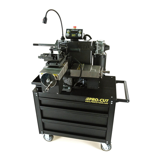
Page 10: Lathe Overview / Components
Lathe Overview PG / 800.543.6618... - Page 11 COMPONENTS Emergency Stop Drum Feed Motor Spindle Start/Stop 1” Arbor Spindle Speed Select Knob LED Task Lamp Feed Start/Stop Spindle Ring Lamp Feed Quality Select Knob Tool Cabinet Base Disc/Drum Cutting Plate Lock Lever Motor Disc Cutting Head Draw Bar Cover Drum Boring Bar Way Covers Drum Insert Holder...
- Page 12 SPECIFICATIONS · 90-264VAC 50/60Hz 1ph Input · Spindle Speed RPM 100-140-180 · Rotor Capacity 4-24” [101.6-609.6mm] · Feeds per Spindle Revolution: (Infinitely Variable) · Maximum width of surface 3.5” [89mm] · Disc 0.0016”-0.0039” [0.04-0.10mm] / rev. · Maximum thickness 2.25” [57mm] ·...
- Page 13 STANDARD ACCESSORIES INCLUDED WITH THE B17 BENCH LATHE 1 Draw Bar with Hex Nut 2 Large Bell Clamp 2 Small Bell Clamp 4 Centering Cones 3 Silencers 6 Double Taper Radius Adapters 1 Standard 1” Arbor 1 Arbor Nut 1 1” Spacer...
-
Page 14: Acceptance From Carrier
Carefully inspect all items received in this shipment. If there is damage or evidence of mishandling in transit, determine the extent of damage and notify the transit company as well as Pro-Cut or your local Pro-Cut rep immediately. Although we are not responsible for damage incurred in transit, we will assist in the preparation and filing of claims. - Page 15 SPECIAL PRECAUTIONS: The Pro-Cut B17 brake lathe was designed to machine the portions of the brake drum & disc brake rotor that come in contact with the friction material. When used according to the instructions herein, this lathe will perform satisfactorily within the work piece size range designed for this model.
- Page 16 Keep the work area well lighted. WORK AREA: Keep the floor around the machine clean and free of foreign materials. Pro-Cut recommends the use of anti-skid floor strips where the operator normally stands, and that each machine has its own work area marked off. Make certain that the work area is well lighted and ventilated.
- Page 17 SAFETY INSTRUCTIONS (continued) DO NOT OVERREACH: Maintain a balanced stance and keep your body under control at all times. HAND SAFETY: Keep hands away from moving parts when the machine is under power. Never clear chips or debris when the machine is under power and never use your hands to clear the chips. Never use compressed air to clean machine; use only a soft bristle brush or vacuum cleaner.
- Page 18 MISUSE: Do not use the machine for other than its intended use. If used for other purposes, Pro-Cut International, LLC, disclaims any expressed or implied warranty, and holds itself harmless for any injury or loss that may result.
-
Page 19: Assembly Of Lathe
· Five mounting holes on the base are provided for this purpose. LUBRICATION Lubricate ways by oiling felt wipers on the end of cross slide every week with Pro-Cut 50-376 way oil or equivalent. For other iron surfaces we recommend high quality rust prevention coating such as CRC brand 3-36 multi-purpose lubricant and corrosion inhibitor. - Page 20 The feed adjustment has 11 quality settings, from the finest finish (1) to the coarsest finish (11). Finer finishes use a lower feed rate, and so take longer. The coarsest finish setting, when used with Pro-Cut inserts is designed to give a finish at or about 100 micro-inch / 2.54 micron Ra, the upper roughness limit allowed for many vehicles.
- Page 21 SETTING UP FOR ROTOR OR DRUM CUTTING The tool support plate can be rotated 90 degrees to disc or drum cutting position. The large lever in the center locks and unlocks the support plate. When the plate is in a valid position, you will see the spindle lamp illumi- nate.
- Page 22 It is dangerous to operate a vehicle with a drum, rotor or flywheel, which has had more material removed than is allowed. Proper operation cannot be established if these specifications have been exceeded. Pro-Cut International recommends that each work piece be checked for size before mounting on the lathe and after machining.
- Page 23 E. Add necessary spacers (double tapered radius adapters may be used as spacers), alignment washers (make sure they are installed concave to convex), and M24x2 hexagonal nut, or Pro-Cut Quick-Nut (de- pending on spindle) and tighten securely. Do not jerk or over tighten. When using Pro-Cut Quick-Nut, washer stack is not necessary as it has an internal convex/concave washer set.
-
Page 24: Mounting Hubbed Drums Or Rotors
6. WRAP RUBBER SILENCER BAND AROUND DRUM, STARTING WITH THE PLAIN END AND MAINTAIN TENSION UNTIL THE CLIP IS SECURED. DO NOT ATTEMPT TO MACHINE DRUMS WITHOUT USING THE SILENCER BAND. Silencer should be nearest open side of drum. Pro-Cut disc silencers should also be used for rotor machining. PG /... - Page 25 MOUNTING HUBBED DRUMS OR ROTORS (Continued) 7. If arbor appears distorted, check for dirty or damaged mounting surfaces and/or adapters. Loosen and re- tighten arbor nut as described above in Step 5. MACHINING HUB-LESS AND HUBBED DRUMS 1. Position the boring bar so that the 45-degree angle tool bit slot is toward the drum, with the cap screw to the top.
- Page 26 Always begin on the single dot corner and rotate clockwise to 2 dots, then 3 dots. On *premium plus cutting tips the first corner is the brand icon. *First side shows the Pro-Cut Brand Icon. DO NOT TURN THESE INSERTS OVER.
- Page 27 MACHINING MODE FROM HOME SCREEN EMERGENCY STOP Spindle Motor Feed ON/OFF ON/OFF Spindle Speed Control: Feed Speed Control: Low-Medium-High 1 (slow/fine) thru 11 (fast/course) WWW.PROCUTUSA.COM PG /...
- Page 28 SET-UP MODE SPINDLE MOTOR MUST BE OFF Set-up Mode: · Long Press > 3 seconds to enter set-up mode. · Rotate to scroll through options and toggle between choices within an option. · Short press to select option or drill down to another level.
- Page 29 STATISTICS MODE SPINDLE MOTOR MUST BE OFF Set-up Mode: · Short Press < 3 seconds to enter Statistics mode. · Rotate to scroll through options and toggle between choices between an option. · Short press to select option or drill down to another level.
-
Page 30: Advanced Tips
Sharp tools are vital to satisfactory operation. When ordering supplies or replacement parts for this machine, always give the model # and serial # of the machine. Use only Genuine Pro-Cut parts. Diagrams for rotor and drum set up with adapters(multiple pages?) PG / 800.543.6618... - Page 31 50-4000 CABLES(NOT SHOWN) PART NUMBER DESCRIPTION QTY. 50-4207 Spindle motor power cable 50-4208 Rotary sensor cable PART ITEM NO. QTY. NUMBER 50-4212 AC Power Cord NEMA 5-15 50-4213 Connect 50-2154,50-2155 and 50-2158. 50-4276 50-4214 Feed motor and Clutch cable 50-4025.1 50-4218 Gooseneck LED power cable(Outside the E-box) 36-4006...
- Page 32 50-4009 ITEM NO. PART NUMBER QTY. 50-4010 50-4011 50-4012 50-4013 50-4014 50-4015 50-4016 50-4017 50-4035 50-4018 50-4019 50-4020 50-4021 50-4022 50-4023 PG / 800.543.6618...
- Page 33 50-1330 ITEM PART QTY. NUMBER 50-1331 37-1333 50-1332 50-1333 50-1334 50-1335 50-1336 50-1339 50-053 50-252 37-1331 50-1343 35-1331 35-1335 37-1332 35-1332 35-1330 37-1330 37-1306 WWW.PROCUTUSA.COM PG /...
- Page 34 DRUM INSTALLATION / Recommended Assembly Bell Clamp Arbor Spring Drum Cone Bell Clamp *Spherical Washer Set Alignment Spacer *Spherical Washer Set PG / 800.543.6618...
- Page 35 DISC INSTALLATION / Recommended Assembly Bell Clamp Arbor Spring Disc/Rotor Cone Bell Clamp *Spherical Washer Set Spacer *Spherical Washer Set WWW.PROCUTUSA.COM PG /...
- Page 36 50-4044 ITEM NO. PART NUMBER QTY. 50-4048 37-4022 35-4008 50-4049 35-4019 37-4018 37-4016 35-4001 50-4047 37-4015 37-4014 50-4050 50-4078 50-4046 37-4020 37-4019 35-4031 35-919 50-4027 50-4045 37-4060 37-4051 35-4004 PG / 800.543.6618...
- Page 37 50-4063 PART ITEM NO. QTY. NUMBER 50-4064 35-4011 37-4026 35-4022 35-4021 50-4006 37-4032 37-4001 35-4000 50-4007 50-4061 37-4033 50-4180 37-4051 WWW.PROCUTUSA.COM PG /...
- Page 38 50-4071 Cables(Not Shown) ITEM PART PART QTY. ITEM NO. DESCRIPTION QTY. NUMBER NUMBER 50-4072 50-4200 Gooseneck LED power cable(Inside the E-box) 50-4205 20pin IDC cable 50-4074 50-4206 24V power input 35-4033 50-4209 50-2159 power cable 50-2154 50-4210 10pin IDC cable 50-2157 50-4211 50-2159 outputs to DB15...
- Page 39 50-4096 50-4192 ITEM NO. PART NUMBER QTY. BOM Table 50-4193 ITEM NO. PART NUMBER QTY. 35-4032 50-4097 50-4098 50-4098 35-4032 WWW.PROCUTUSA.COM PG /...
- Page 40 50-4170 Cables(Not shown) item No. Part Number Describtion QTY. ITEM NO. PART NUMBER QTY. 50-4201 Rotary control cable 50-4171 50-4204 10pin to DB15 50-2155 50-4221 Spindle start/stop button and cable 35-801 50-4222 Feed start/stop button and cable 50-4217 E-stop button and cable 50-2145 50-2241 35-4041...
- Page 41 50-4274 ITEM PART QTY. NUMBER 50-4051 50-4052 50-4053 35-4005 36-4003 37-4061 37-4028 50-4032 35-4030 35-4001 50-4026 50-4043 35-4028 WWW.PROCUTUSA.COM PG /...
- Page 42 50-4275 ITEM PART QTY. NUMBER 50-4055 50-4032 35-4030 50-4053 35-4028 50-4052 37-4061 36-4003 35-4005 37-4028 50-4026 35-4001 50-4043 PG / 800.543.6618...
- Page 43 50-4276 ITEM PART QTY. NUMBER 37-4009 50-4057 37-4007 37-4003 37-4004 50-4056 37-4010 37-4005 37-4006 37-4011 50-4058 37-4030 35-4004 50-4070 35-4001 50-4060 37-4008 35-4015 50-4137 50-4800 WWW.PROCUTUSA.COM PG /...
- Page 44 50-4277 ITEM PART NUMBER QTY. 37-4024 50-4090 35-4006 37-4045 50-4024 50-4139 35-4026 36-4017 35-4036 PG / 800.543.6618...
- Page 45 50-4279 ITEM NO. PART NUMBER QTY. 50-4005 50-4008 35-4020 WWW.PROCUTUSA.COM PG /...
-
Page 46: Maintenance Schedule
MAINTENANCE SCHEDULE DATE NOTES DRO READINGS MONTH / DAY / YEAR | HOURS | TOTAL DISCS | TOTAL DRUMS | PG / 800.543.6618... - Page 47 MAINTENANCE SCHEDULE DATE NOTES DRO READINGS MONTH / DAY / YEAR | HOURS | TOTAL DISCS | TOTAL DRUMS | WWW.PROCUTUSA.COM PG /...
- Page 48 PG / 800.543.6618...
- Page 49 WWW.PROCUTUSA.COM PG /...
- Page 50 50-4149 PRINTED WITH PRIDE IN THE U.S.A. Pro-Cut International, LLC 10 Technology Drive #4 West Lebanon, NH 03784 P. 800.543.6618 / 603.298.5200 Global inquiries please see: F. 603.298.8404 www.procutusa.com E. info@procutusa.com © PRO-CUT INTERNATIONAL, LLC...
Need help?
Do you have a question about the B17 and is the answer not in the manual?
Questions and answers