Table of Contents
Advertisement
Advertisement
Table of Contents
Troubleshooting

Related Manuals for Pro-Cut PFM 9.0 DRO


Summary of Contents for Pro-Cut PFM 9.0 DRO
- Page 1 TECHNICAL MANUAL...
- Page 3 TECHNICAL MANUAL P · 800.543.6618 F · 603.298.8404 info@procutusa.com www.procutusa.com...
- Page 4 OUR MISSION Pro-Cut International is dedicated to providing our customers with the most advanced, pre- cise, and profitable tools for brake repair. We have worked with, learned from and solved problems for people at all levels of the brake repair business - from the largest auto manufac- turers and national service chains to one-bay, one-man operations.
- Page 5 For the period of one (1) year from the original date of purchase, if we determine that the equipment is defective subject to the limitations of this warranty, we will replace it at no charge for labor. Pro-Cut International warrants any such work done against defects in materials or workmanship for the remaining portion of the original warranty period.
-
Page 6: Table Of Contents
CONTENTS Pro-Cut Mission Maintenance Safety and Warning Information Troubleshooting: Assuring a Smooth Finish Introduction Troubleshooting: Lateral Run-out Adjustment Lateral Run-out Defined Troubleshooting: Raising or Lowering the Acceptance Number 9.0 DRO Lathe Overview DRO Compensation Instructions Lathe Setup Adapter Guide Vehicle Preparation 42-49 9.0 DRO Parts Diagrams... - Page 7 IMPORTANT SAFETY INSTRUCTIONS The 9.0 DRO Rotor Matching System is a precision instrument which requires close attention while in operation. It will provide many years of service if it is operated safely. Basic Safety precautions should always be followed, including the following: Read all instructions Care must be taken as burns can occur from touching hot parts.
-
Page 8: Introduction
INTRODUCTION WELCOME TO THE PRO-CUT TEAM. Congratulations on your purchase of the PRO-CUT 9.0 DRO, the world’s fastest and most accurate computer- ized on-car brake lathe. For many years, on-car lathes were used only for rotors that were difficult to remove. Due to current trends, virtually all auto manufacturers now require or recommend the use of on-car technology to match every rotor to every hub. - Page 9 YOUR LATHE PACKAGE Every Pro-Cut 9.0 DRO Lathe Package comes complete, ready to assemble and use. Setup and training is in- cluded by a local, certified Pro-Cut Rep. Please contact Pro-Cut at 800-543-6618 immediately if you have not already made arrangements for on-site training. Here’s what’s included in a standard lathe package:...
- Page 10 Run-out DEFINED LATERAL Run-out leads to ... THICKNESS VARIATION which results in ... BRAKE PEDAL PULSATION. PG / 800.543.6618 Ø1Ø...
- Page 11 (0.05mm). The 9.0 DRO Rotor Matching System allows you to match every rotor to the hub on which it turns. The on-board computer delivers a precise alignment between the lathe axis and the hub axis, thereby guaranteeing that a Pro-Cut machined rotor will have less than 0.001” (0.025mm) lateral run-out every time.
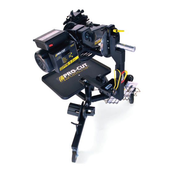
- Page 12 Lathe Overview *Guard 50-1730 Not Shown PG / 800.543.6618 Ø12...
- Page 13 COMPONENTS 9.0 DRO Computer Box Automatic Shut-off Switch On/Off Switch Automatic Shut-off Cam 120V 60 Hz or 1.5 hp 230V 50/60 Hz hp Motor Cut Depth Adjustment Dials Draw Bar Knob Cutting Tips/Inserts Adjustment Flange (obscured) Tool Arm Lock Lever Adjustment Solenoid (obscured) Trolley...
- Page 14 SETTING UP A NEW LATHE Before you begin setting up, check contents against the parts diagram enclosed in the lathe package. If you are missing any parts, call Pro-Cut immediately. PG / 800.543.6618 Ø14...
- Page 15 Cutting ASSEMBLE THE TROLLEY Open the trolley box and check contents against the parts diagram . If you are missing any parts, call Pro-Cut immediately. Proceed with assembly, following the instructions enclosed in the box. Edge MOUNT THE LATHE TO THE TROLLEY Once the trolley is assembled you will need to mount the lathe to the trolley.
-
Page 16: Vehicle Preparation
VEHICLE PREPARATION Before lifting the vehicle, the front wheels should be straight and the parking brake should be off, with the transmission in neutral. 1. Raise the vehicle according to the lift manufacturer’s instructions. Raise until the wheel hub is about belt level. 2. - Page 17 NOTE It is important to start on the proper side. The Pro-Cut mounts directly to the hub of the vehicle. With the lathe right-side up (FIG:1) the cutting head is to the right of the hub as you face the vehicle wheel well.
-
Page 18: Lathe Preparation: Checking Cutting Tips
Before mounting the lathe, check the cutting tips and make sure they are ready for use. The cutting tips are one of the most critical components of the machine. It is vital that they are Pro-Cut brand tips in good condition and properly mounted. Each cutting tip has three corners which may be used. -
Page 19: Step 1: Mount The Adapter
Step 4: Make the Cut (3-4 mins.) steel like wheels. They are not designed to withstand If the four steps are followed properly on each brake job, the Pro-Cut 9.0 DRO RMS will operate accurately and efficiently. the use of impact tools. DO NOT USE IMPACT... - Page 20 MACHINING ROTORS CONTINUED STEP 2: SET UP THE LATHE (2 Minutes) A. Mount the Lathe to the Adapter Move the cutting head out so that the tips will not strike the rotor as you mount the lathe. Next, roll the machine into place and match it up with the adapter. Note that the trolley moves up and down to accommodate different heights.
-
Page 21: Step 2: Set Up The Lathe
NOTE: The Pro-Cut will mount cutting head up on one side and cutting head down on the other. Always start right-side up; this way, when you proceed to the other side of the vehicle, the offset of the cutting head, and the shut-off cam will already be set. -
Page 22: Step 3: Adjust For Lateral Run-Out
MACHINING ROTORS STEP 3: ADJUST FOR LATERAL Run-out (1 Minute) You must adjust for lateral run-out to eliminate wobble (run-out) from the machine before cutting. This procedure en- sures the resulting machined rotor will have minimal run-out after cutting. The 9.0 DRO Rotor Matching System has been calibrated to reduce run-out to less than 0.001”... - Page 23 MACHINING ROTORS STEP 3: ADJUST FOR LATERAL Run-out CONTINUED (1 Minute) If the TRY AGAIN light is illuminated, the machine is unable to fully adjust for run-out. This dif- NOTE ficulty could be due to looseness of fittings, irregular run-out, damage to wheel bearings or other components, or other factors relating to set-up.
- Page 24 MACHINING ROTORS Step 4: MAKE THE CUT (4 Minutes) With the motor still running, loosen the forward lock lever on the cutting head to allow cutting depth adjustment. Turn cut-depth knobs counter-clockwise until the tips can clear both sides of the rotor. Crank the cutting head in to the middle of the braking surface of the rotor.
- Page 25 The 50-754 chip deflector/silencer works well on the thin solid rear rotors In 2012 Pro-Cut will introduce a third type, which has wide pads and a wider wire loop which will make this type function better on thicker rotors.
-
Page 26: Step 4: Make The Cut
Cleaning the rotor surface after machining to remove all dust and debris is very important in the overall quality of the brake job. Pro-Cut recommends using liberal amounts of warm water with a mild detergent and drying thoroughly with clean towels to be certain all loose material is removed. -
Page 27: Machining The Opposite Side
MACHINING ROTORS MACHINING THE OPPOSITE SIDE Loosen the trolley disc lock lever and rotate the machine into the upside-down position. NOTE The procedure for cutting in the upside-down position is the same, though fewer steps are needed as the lateral orientation of the cutting head relative to the rotor is already set. The lathe mounts in the same Be sure the auto shut-off manner. -
Page 28: Vehicle Reassembly
Special care should be used in making sure that ABS sensors are free of debris. Reassemble the brakes and wheels to the manufacturer’s specifications. HELPFUL HINTS FOR CUTTING ROTORS USING A PRO-CUT LATHE – Inspect cutting tip edge for wear and damage. -
Page 29: Maintenance
MAINTENANCE The Pro-Cut lathe is simple and rugged. With just a few maintenance tips you can ensure a long and profitable life for your machine. Check cutting tip edges. If there are chips or dings, turn or replace the tip. Be sure they are right-side up so that the groove and dots are visible. -
Page 30: Troubleshooting Assuring A Smooth Finish
NOTE Brake performance is dependent upon rotor surface finish as well as minimizing lateral run-out. The Pro-Cut lathe is designed to give you a superior surface finish on any rotor as long as proper maintenance is followed. The Pro-Cut 9.0 DRO should... - Page 31 The chip deflector must be used on every cut to ensure proper finish. New chip deflectors can be purchased directly from Pro-Cut. For thin, solid rotors a heavy- duty chip deflector/silencer (50-751) is available.
- Page 32 TIGHTENING THE GIB Poor finish quality can be the result of a loose cutting head. As wear occurs between the slide plate and the gear box it rides on, you must take up the slack. You do this by tightening the moveable wedge we call the “gib” (50-463). If the cutting head can be moved from side to side at all, it should be tightened.
-
Page 33: Troubleshooting: Lateral Run-Out Adjustment
CALIBRATION PROCEDURE The Pro-Cut 9.0 DRO Rotor Matching System is calibrated with an acceptance number from the factory. Normally, this will never need to be changed. Please call Pro-Cut Service Department before attempting calibration procedure to confirm that this is the problem. - Page 34 Once you have raised or lowered the acceptance number by two and hit RESET, test the machine to ensure that the problem has been solved. You may need to repeat the procedure once or twice to fully solve the problem. If you have any difficulty or questions about executing this procedure, call Pro-Cut. PG / 800.543.6618...
- Page 35 TROUBLESHOOTING All 9.0 DRO DRO machines are calibrated to a value of 1.0 from the factory. This value should give the best performance and should only be changed at the direction of a qualified Pro-Cut service tech. NOTE Higher binary codes will yield a wider acceptance range.
-
Page 36: Dro Compensation Instructions
By checking these values on a monthly basis, managers can track their ROI based on the machine usage. Pro-Cut Service Technicians can also check the accuracy of the machine over time. The first screen that you will see when the machine is plugged in (after the computer "boots up") is the Ready Mode. - Page 37 DRO EFFICIENCY TRACKING The remaining screens are accessed through the START button and are scrolled through by continued pressing of the START button. The machine first must be in the Ready mode and the motor must be off. Press and hold the START button until all of the lights come on, then release and the Hour screen will be displayed .
- Page 38 DRO EFFICIENCY TRACKING Press the START button again and the word "Total" will be displayed. Press the START button once more and the total number of times the machine has compensated will be displayed. This value represents the total number of completed compensation cycles.
- Page 39 DRO DIAGNOSTICS CONTINUED This value represents the average compensation time recorded in seconds over the life of the lathe. Press the START button again and the word "5 Adj." screen will be displayed. Press the START button once more and the last five adjustment cycle times will be displayed in seconds.
- Page 40 ADAPTERS STANDARD ADAPTER PACKAGES 50-687 50-688 50-695 50-691 SMALL TRUCK/LARGER CAR ADAPTER 4-HOLE ADAPTER 5-HOLE ADAPTER 1/2-TON TRUCK ADAPTER/COMMON Fits most 4-lug vehicles. Fits most smaller 5-lug Fits many small trucks and SUV’s as well Fits most pickups and sport utility as larger passenger cars.
- Page 41 50-694 50-683 50-935 50-681 TALL HUB TRUCK ADAPTER 3/4 TON TRUCK ADAPTER/COMMON DUAL WHEEL TRUCK TOYOTA SPECIALTY & ALTERNATE ADAPTER TRUCK ADAPTER Primarily used to fit the 2003+ Fits most 3/4 ton single wheel trucks Expedition and 2004+F150, front and rear. Fits 1-ton Ford, Dodge, and Fits most pickups and SUVs including the Toyota Land Cruiser and VW Touareg (does...
-
Page 42: Dro Parts Diagrams
PFM-9.05 (220V) Shown 50-1826 50-1110 *Notes: 50-364 1. 220V: 50-9052 120V: 50-9002 36-113 2. 220V:50-531, 120V: 50-539 50-837 37. 220V: 50-235, 120V: 50-238 9/4/2012 50-838 46. Includes (2) M8x20 Cap Screws (C) Pro-Cut International LLC, Ltd. 50-1247* PG / 800.543.6618 Ø42... - Page 43 9.0 DRO PARTS DIAGRAM 50-235 CUTTING HEAD ASSEMBLY PART ITEM NO. NUMBER QTY. 50-292 50-253 50-254 50-373 50-374 50-085 50-251 50-252 50-053 37-077 37-184 37-003 37-082 50-365 50-364 36-010 36-002 Note: 37-077 Arrange like this: )( 9/4/2012 WWW.PROCUTUSA.COM PG / Ø43...
- Page 44 9.0 DRO PARTS DIAGRAM 50-238 CUTTING HEAD ASSEMBLY ITEM PART NUMBER QTY. 50-292 50-373 50-374 50-253 50-254 50-098 50-252 50-251 50-053 37-077 37-184 36-002 37-003 37-082 50-365 37-077 50-364 36-010 Assembly: 9/4/2012 PG / 800.543.6618 Ø44...
-
Page 45: Bevel Gear Box
9.0 DRO PARTS DIAGRAM BEVEL GEAR BOX ITEM PART NUMBER QTY. 37-056 50-021 35-926 M12 this end. 50-016 50-018 37-057 37-927 50-062 50-014 9/4/2012 QTY MAY VARY. WWW.PROCUTUSA.COM PG / Ø45... - Page 46 9.0 DRO PARTS DIAGRAM 50-380 PRO-CUT TROLLEY ITEM PART QTY. NUMBER 35-425 37-015 35-258 36-021 ITEM PART NUMBER QTY. 50-1034 50-348 50-1039 37-617 37-465 50-1042 35-253 50-1038 37-468 37-475 37-467 50-1057 50-307 50-312 37-032 50-336 36-001A 50-750.2 37-108 50-750.1 37-622...
- Page 47 9.0 DRO PARTS DIAGRAM 50-390 PRO-CUT TROLLEY WWW.PROCUTUSA.COM PG / Ø47...
- Page 48 9.0 DRO PARTS DIAGRAM 50-1730 PRO-CUT SPINDLE GUARD ITEM NO. PART NUMBER QTY. 50-1731 37-1730 35-275 37-003 35-819 Tap M8x1.25 two places on motor. No tap drill needed. PG / 800.543.6618 Ø48...
- Page 49 9.0 DRO PARTS DIAGRAM PART NO. 50-1165 ITEM NO. PART NUMBER DESCRIPTION QTY. 50-1812 Electronics Box Base 9.0 DRO Electronics Assembly 50-1175 with 50-1154 PCB 50-1814 Electronics Box Gasket 35-806 CR-PHMS #6-32x3/8-SS 9/4/2012 ADHESIVE THIS SIDE. WWW.PROCUTUSA.COM PG / Ø49...
-
Page 50: Maintenance Schedule
MAINTENANCE SCHEDULE DATE NOTES DRO READINGS MONTH / DAY / YEAR | HOURS | TOTAL | AVERAGE | LAST 5 | PG / 800.543.6618 Ø5Ø... - Page 51 MAINTENANCE SCHEDULE DATE NOTES DRO READINGS MONTH / DAY / YEAR | HOURS | TOTAL | AVERAGE | LAST 5 | WWW.PROCUTUSA.COM PG / Ø51...
- Page 52 50-727 PRINTED WITH PRIDE IN THE U.S.A. Pro-Cut International, LLC 10 Technology Drive #4 West Lebanon, NH 03784 P. 800.543.6618 / 603.298.5200 Global inquiries please see: F. 603.298.8404 www.procutusa.com E. info@procutusa.com © PRO-CUT INTERNATIONAL, LLC...
Need help?
Do you have a question about the PFM 9.0 DRO and is the answer not in the manual?
Questions and answers