Chapters
Table of Contents

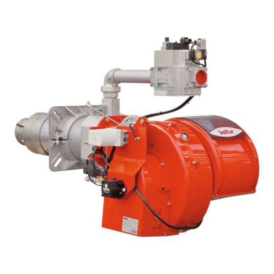
Related Manuals for baltur TBML 80 PN


Summary of Contents for baltur TBML 80 PN
- Page 1 Manual instructions for use Manuale istruzioni per l'uso. TBML 80 PN TBML 160 PN - BRUCIATORI MISTI GAS / GASOLIO A DUE STADI PROGRESSIVI / MODULANTI ISTRUZIONI ORIGINALI (IT) 0006081428_201406...
- Page 3 Prima di iniziare a usare il bruciatore leggere attentamente quanto esposto nell’ouscolo “AVVERTENZE PER L’UTENTE, PER L’USO IN SICUREZZA DEL BRUCIATORE” presente a corredo del manuale istruzioni, che costituisce parte integrante ed essenziale del prodotto. Leggere attentamente le istruzioni prima di mettere in funzione il bruciatore o di eseguire la manutenzione. I lavori sul bruciatore e sull’impianto devono essere eseguiti solo da personale qualificato.
-
Page 4: Table Of Contents
ACCENSIONE E REGOLAZIONE A GAS METANO ............................... 21 REGOLAZIONE CAMME SERVOMOTORE SQN 30.401 .............................. 26 REGOLAZIONE CAMME SERVOMOTORE STA5B0.36/83N23 ............................ 26 MANUTENZIONE TBML 80 PN ...................................... 27 MANUTENZIONE TBML 160 PN ....................................28 ISTRUZIONI PER L’ACCERTAMENTO DELLE CAUSE DI IRREGOLARITÀ’ NEL FUNZIONAMENTO E LORO ELIMINAZIONE ......31 SCHEMA ELETTRICO ........................................ - Page 5 L’eventuale riparazione dei prodotti dovrà essere effettuata solamente incombusti nocivi o inquinanti oltre i limiti consentiti dalle norme vigenti. da un centro di assistenza autorizzato dalla BALTUR utilizzando d) Verifi care la funzionalità dei dispositivi di regolazione e di sicurezza.
- Page 6 ALIMENTAZIONE ELETTRICA - b) la regolazione della portata del combustibile secondo la potenza • La sicurezza elettrica dell’apparecchio è raggiunta soltanto quando lo richiesta al bruciatore; stesso è corretamente collegato a un’efficace impianto di messa a terra, - c) che il bruciatore sia alimentato dal tipo di combustibile per il quale eseguito come previsto dalle vigenti norme di sicurezza.
-
Page 7: Caratteristiche Tecniche
CARATTERISTICHE TECNICHE TBML 80 PN TBML 160 PN 1600 POTENZA TERMICA < 80 mg/kWh (Classe III secondo EN 676) EMISSIONI NOx Bistadio progressivo / modulante FUNZIONAMENTO 1600 POTENZA TERMIC PRESSIONE MAX mbar EMISSIONI NOx 1600 POTENZA TERMICA < 185 mg/kWh (Classe II secondo EN 267) EMISSIONI NOx 5,5 cst/20°... - Page 8 680 310 370 580 380 200 1280 270 440 180 178 280 250 325 M12 190 222 12 TBML 80 PN TBML 160 PN 695 325 370 580 380 200 1300 285 450 224 219 320 280 370 M12 235 260 12 112,5 54...
-
Page 9: Applicazione Del Bruciatore Alla Caldaia
CAMPO DI LAVORO I campi di lavoro sono ottenuti su caldaie di prova rispondenti Potenza termica Metano alla norma EN 267 e sono orientativi per gli accoppiamenti Potenza termica Gasolio bruciatore caldaia. Per il corretto funzionamento del bruciatore le dimensioni della camera di combustione devono essere rispondenti alla normativa vigente;... - Page 10 Tubo rigido rilevamento pressione in camera di combustione Vite fissaggio tubo rigido Presa di pressione in camera di combustione Tagliare a filo diffusore Tubo trasmissione pressione in camera di combustione MONTAGGIO RAMPA GAS MONTAGGIO CORPO VENTILANTE Sono possibili diverse soluzioni di montaggio della ram- •...
-
Page 11: Linea Di Alimentazione Gas
LINEA DI ALIMENTAZIONE GAS Lo schema di principio della linea di alimentazione gas è riportato nella figura sotto. La rampa gas è omologata secondo normativa EN 676 e viene fornita separatamente dal bruciatore. Occorre installare, a monte della valvola gas, una valvola di intercettazione manuale e un giunto antivibrante, disposti secondo quanto indicato nello schema. -
Page 12: Linea Di Alimentazione Gasolio
4 - Ugello 1° fiamma 5 - Valvola sicurezza normalmente chiusa 6 - Pompa 12 bar N.B. Perdita di carico circuito idraulico TBML 80 PN = 1 bar 7 - Valvola normalmente chiusa TBML 160 PN = 2 bar 10 / 36... - Page 13 TABELLA DIMENSIONAMENTO TUBAZIONE TBML 80 PN IMPIANTO DI ALIMENTAZIONE PER GRAVITA’ 1 Serbatoio 6 Tubo di aspirazione 2 Tubazione di alimentazione 7 Tubo ritorno bruciatore 3 Filtro a rete 8 Dispositivo automatico intercettazione 4 Pompa a bruciatore fermo 5 Degasificatore 9 Valvola unidirezionale L.
- Page 14 TABELLA DIMENSIONAMENTO TUBAZIONE TBML 160 PN IMPIANTO DI ALIMENTAZIONE PER GRAVITA’ 1 Serbatoio 6 Tubo di aspirazione 2 Tubazione di alimentazione 7 Tubo ritorno bruciatore 3 Filtro a rete 8 Dispositivo automatico intercettazione 4 Pompa a bruciatore fermo 5 Degasificatore 9 Valvola unidirezionale L.
- Page 15 PARTICOLARI POMPA SUNTEC ATTACCO MANOMETRO E SFOGO ARIA (1/8” G) AJ4 - AJ6 VITE REGOLAZIONE PRESSIONE 3.1 ASPORTARE IL DADO PER ACCEDERE ALLA VITE DI REGOLAZIONE DELLA PRESSIONE (AN..11-14 BAR, AJ..11-16 BAR) RITORNO 4.1 RITORNO CON GRANO DI BY-PASS INTERNO ASPIRAZIONE MANDATA ATTACCO VUOTOMETRO (1/8”...
-
Page 16: Collegamenti Elettrici
COLLEGAMENTI ELETTRICI La linea di alimentazione trifase deve essere provvista di interrut- tore con fusibili. E’ inoltre richiesto dalle Norme un interruttore sulla linea di alimentazione del bruciatore, posto all’esterno del locale caldaia in posizione facilmente raggiungibile. Per i collegamenti elettrici (linea e termostati) attenersi allo schema elettrico allegato. -
Page 17: Apparecchiatura Di Comando E Controllo Bruciatori A Gas Lme
APPARECCHIATURA DI COMANDO E CONTROLLO BRUCIATORI A GAS LME ... Funzionamento, indicazioni, diagnstica Il pulsante di sblocco «EK...» è l’elemento principale per poter accedere a tutte le funzioni di ROSSO diagnostica (attivazione e disattivazione), oltre a sbloccare il dispositivo di comando e controllo. Il «LED»... - Page 18 Diagnosi della causa di malfunzionamento e blocco In caso di blocco bruciatore nel pulsante di sblocco sarà fissa la luce rossa. Premendo per più di 3 sec. la fase di diagnosi verrà attivata (luce rossa con lampeggio rapido), nella tabella sottostante viene riportato il significato della causa di blocco o malfunzionamento in funzione del numero di lampeggi (sempre di colore rosso).
- Page 19 AGK25... Resistenza PTC Schema dei collegamenti e controllo della sequenza di lavoro AL Messaggio di errore (allarme) dell’apparecchiatura LME22… BCI Interfaccia di Comunicazione del Bruciatore BV... Valvola del Combustibile CPI Indicatore di Posizione Chiusa Dbr.. Ponticello cablaggio EK.. Pulsante di reset del blocco remoto (interno) EK2 Pulsante di reset del blocco remoto ION Sonda di Ionizzazione FS Segnale di Fiamma...
-
Page 20: Descrizione Del Funzionamento Con Combustibile Liquido
con aria della camera di combustione e contemporaneamente DESCRIZIONE DEL la pompa del combustibile che determinano una circolazione nei FUNZIONAMENTO CON condotti espellendo, attraverso il ritorno, eventuali bolle di gas. Questa fase di prelavaggio ha termine con l’apertura dell’elettrovalvole COMBUSTIBILE LIQUIDO di sicurezza e di 1°... -
Page 21: Primo Riempimento Tubazione
nella sua posizione iniziale e ripeterebbe automaticamente tutta la pompa non ne è provvista, asportare il tappo fase di accensione del bruciatore. dell’attacco manometro. • Collegare il tubo flessibile di ritorno alla tubazione ed aprire le Da quanto sopra esposto risulta evidente che saracinesche poste su questo tubo. -
Page 22: Descrizione Del Funzionamento Con Combustibile Gassoso
• Regolare l’aria della quantità che si presume necessaria per la Precisiamo che: portata massima (2° fiamma) agendo sull’apposita camma del • La valvola principale è provvista di dispositivo per la regolazione servomotore elettrico (pagina 26) proporzionale del rapporto aria/gas. •... -
Page 23: Accensione E Regolazionea Gas Metano
sposti per il valore di tensione disponibile. Verificare che tutti i combustione e, di conseguenza del gas, fino a raggiungere l’e- collegamenti elettrici, realizzati sul posto, siano correttamente rogazione massima cui il bruciatore è stato regolato. L’aumento eseguiti come da nostro schema elettrico. della pressione dell’aria nel ventilatore viene rilevata dal sensore della valvola gas, di tipo proporzionale, che adegua gradualmente •... - Page 24 - Il “bloccaggio” con presenza di fiamma, può essere causato fino al valore ottimo del 10% oppure O = 3% per l’erogazione da instabilità della stessa nella zona di ionizzazione, per un massima. E’ indispensabile verificare con l’apposito strumento rapporto aria/gas non corretto. Si rimedia variando la quantità che la percentuale di ossido di carbonio (CO) presente nei fumi di aria e/o di gas erogati in modo da trovare il corretto rap- non superi il valore imposto dalla normativa vigente al momento...
- Page 25 in caso contrario l’apparecchiatura di comando e controllo non • Verificare l’efficienza dei termostati o pressostati di caldaia viene inserita (il bruciatore resta fermo). (l’intervento deve arrestare il bruciatore). • I pressostati di controllo della pressione del gas Controllare che l’accensione avvenga (minima e massima), se installati, hanno lo scopo di impedire il regolarmente perché, nel caso in cui si funzionamento del bruciatore quando la pressione del gas non...
- Page 26 straccio l’apertura dedicata al rilevatore fiamma. La fiamma del bruciatore deve così spegnersi. L’apparecchiatura nel tempo determinato dal programma, si porta in blocco. Sbloc- care l’apparecchiatura solo con intervento manuale pigiando sull’apposito pulsante. • Per controllare l’efficienza dei termostati, si fa funzionare il bruciatore fino a quando l’acqua in caldaia raggiunge la temperatura di almeno 50°...
- Page 27 Dopo aver montato gli ugelli, verificare il corretto posizionamento di elettrodi e disco, secondo le quote indicate in mm. UGELLI CONSIGLIATI: STEINEN tipo SS 45° (TBML 80 PN) E’ opportuno eseguire una verifica delle quote dopo ogni MONARCH tipo HV 45° (TBML 160 PN) intervento sulla testa.
-
Page 28: Regolazione Camme Servomotore Sqn 30.401
REGOLAZIONE CAMME SERVOMOTORE SQN 30.401 CAMME REGOLABILI 1 Perno di inserzione ed esclusione accoppiamento motore - albero camme. 2 Scala di riferimento 3 - Indicatore di posizione Camma regolazione apertura massima aria (70°) II Chiusura totale aria (bruciatore fermo) (0°) III Camma regolazione aria per minima gas (20°) IV Camma regolazione aria 1°... -
Page 29: Manutenzione Tbml 80 Pn
MANUTENZIONE TBML 80 PN Effettuare almeno una volta all’anno e comunque in conformità alle norme vigenti, l’analisi dei gas di scarico della combustione verificando la correttezza dei valori di emissioni. Controllare il filtro del combustibile, se è sporco sostituirlo. Verificare che tutti i componenti della testa di combustione siano in buono stato, non deformati dalla temperatura e privi di impurità... -
Page 30: Manutenzione Tbml 160 Pn
MANUTENZIONE TBML 160 PN Effettuare almeno una volta all’anno e comunque in conformità alle norme vigenti, l’analisi dei gas di scarico della combustione verificando la correttezza dei valori di emissioni. Controllare il filtro del combustibile, se è sporco sostituirlo. Verificare che tutti i componenti della testa di combustione siano in buono stato, non deformati dalla temperatura e privi di impurità... - Page 31 • Controllo combustione PRECISAZIONI SULL’USO DEL Per Contenere i consumi e principalmente per evitare gravi PROPANO inconvenienti, regolare la combustione impiegando gli appositi strumenti. E’ assolutamente indispensabile accertare che la per- • Valutazione, indicativa, del costo di esercizio centuale di ossido di carbonio (CO) non superi il valore massimo - 1 m di gas liquido in fase gassosa ha un potere calorifico ammesso dello 0,1% (impiegare l’analizzatore di combustione).
- Page 32 SCHEMA DI PRINCIPIO PER RIDUZIONE PRESSIONE G.P.L. A DUE SALTI PER BRUCIATORE O CALDAIA Manometro e presa di pressione Riduttore di 2° salto; Uscita = ~ 30 mbar Portata = circa il doppio del massimo richiesto dall’utilizzatore Bruciatore Filtro Giunto antivibrante Filtro (tipo vapore) Riduttore di 1°...
-
Page 33: Istruzioni Per L'accertamento Delle Cause Di Irregolarità' Nel Funzionamento E Loro Eliminazione
ISTRUZIONI PER L’ACCERTAMENTO DELLE CAUSE DI IRREGOLARITÀ’ NEL FUNZIONAMENTO E LORO ELIMINAZIONE NATURA IRREGOLARITÀ’ CAUSA POSSIBILE RIMEDIO 1) Termostati (caldaia o ambiente) o pres- 1) Alzarne il valore o attendere che si chiudano Bruciatore che non si avvia. sostati, aperti per diminuzione naturale della temperatura (l’apparecchiatura non effettua 2) Fotoresistenza in corto circuito... - Page 34 NATURA IRREGOLARITÀ’ CAUSA POSSIBILE RIMEDIO 1)Fotoresistenza interrotta o sporca di fumo 1) Pulirla o sostituirla L’apparecchio va in blocco con la 2) Tiraggio insufficiente 2) Controllare tutti i passaggi dei fumi nella fiamma (lampada rossa accesa) il 3) Circuito del rilevatore fiamma interrotto caldaia e nel camino guasto è...
- Page 35 TABELLA PORTATA UGELLI Pressione pompa Ugello Ugello G.P.H. Portata all’uscita dell’ugello G.P.H. 0,40 1,27 1,36 1,44 1,52 1,59 1,67 1,73 1,80 1,86 1,92 1,98 2,04 2,10 2,15 2,20 0,40 0,50 1,59 1,70 1,80 1,90 1,99 2,08 2,17 2,25 2,33 2,40 2,48 2,55 2,62...
-
Page 36: Schema Elettrico
SCHEMA ELETTRICO 34 / 36 0006081428_201406... - Page 37 SIGLA DIN / IEC APPARECCHIATURA GNYE VERDE / GIALLO CONTROLLO TENUTA VALVOLE ACCESSORIO PER UV BRUNO FOTOCELLULA UV NERO RELE’ TERMICO CONNETTORE NERO CON SOVRASTAMPA FUSIBILI SPIA BLOCCO ESTERNA SPIA DI FUNZIONAMENTO SPIA FUNZIONAMENTO OLIO SPIA FUNZIONAMENTO GAS SPIA FUNZIONAMENTO VENTILATORE SPIA FUNZIONAMENTO 2°...
- Page 38 36 / 36 0006081428_201406...
- Page 39 • Before using the burner for the first time please carefully read the chapter “WARNINGS NOTES FOR THE USER : HOW TO USE THE BURNER SAFELY” in this instruction manual, which is an integral and essential part of the product. The works on the burner and on the esystem have to be carried out only by competent people.
- Page 40 STARTING UP AND REGULATION WITH METHANE GAS ............................21 CAM REGULATION ON SERVOMOTOR SQN 30.401 ..............................26 CAM REGULATION ON SERVOMOTOR STA5B0.36/83N23 ............................26 TBML 80 PN MAINTENANCE ......................................27 TBML 160 PN MAINTENANCE ....................................... 28 HOW TO FIND THE CAUSES OF IMPROPER OPERATION AND TROUBLESHOOTING ...................31 ELECTRIC DIAGRAM ........................................
- Page 41 In such case get in touch with only qualifi ed technicians. Any c) Carry out a check on combustion to ensure the production of no- product repairs must only be carried out by BALTUR authorised assi- xious or polluting unburnt gases does not exceed limits permitted stance centres using only original spare parts.
- Page 42 ELECTRICAL SUPPLY • Have qualifi ed technicians check the following: • The equipment is electrically safe only when it is correctly connected to an a) that the feed line and the train comply with current law and regulations. effi cient ground connection carried out in accordance with current safety b) that all the gas connections are properly sealed.
-
Page 43: Technical Specifications
TECHNICAL SPECIFICATIONS TBML 80 PN TBML 160 PN 1600 THERMAL CAPACITY < 80 mg/kWh (Class III according to EN 676) NOx EMISSIONS Modulating / Progressive two stage burner OPERATION 1600 THERMAL CAPACITY PRESSURE MAX mbar NOx EMISSIONS 1600 THERMAL CAPACITY <... - Page 44 680 310 370 580 380 200 1280 270 440 180 178 280 250 325 M12 190 222 12 TBML 80 PN TBML 160 PN 695 325 370 580 380 200 1300 285 450 224 219 320 280 370 M12 235 260 12 112,5 54...
-
Page 45: Burner Connection To The Boiler
OPERATING RANGE The working ranges are obtained from test boilers corresponding Thermal power of methane gas to the standard EN267 and are indicative of the combination Thermal power of diesel oil burner-boiler. For correct working of the burner the size of the combustion chamber must correspond to current regulations;... - Page 46 Rigid pressure detection pipe in the combustion chamber Rigid pipe fixing screw Pressure intake in the combustion chamber Cut flush with diffuser Pressure transmission pipe in the combustion chamber ASSEMBLING VENTILATING UNIT ASSEMBLING THE GAS TRAIN • Position the half-hinges on the burner scroll in line with those There are different ways of assembling the valve train as shown on the combustion head assembly.
-
Page 47: Gas Supply Line
GAS SUPPLY LINE The gas supply scheme is shown in the diagram below. The gas train is certified in accordance with regulation EN 676 and is supplied separately from the burner. A manual shut off valve, an interception valve and an anti-vibration joint must be installed upstream of the gas valve, as shown in the diagram. -
Page 48: Diesel Oil Supply Line
4 - 1 flame nozzle Note: Pressure loss in hydraulic circuit TBML 80 PN = 1 bar 5 - Safety valve normally closed TBML 160 PN = 2 bar 6 - 12 bar pump 7 - Valve normally closed... - Page 49 PIPELINE SIZE TABLE TBML 80 PN GRAVITY SUPPLY SYSTEM 1 Tank 6 Suction pipe 2 Feeding pipe 7 Return pipe 3 Wire-net filter 8 Automatic fuel interception at burner shut off 4 Pump 9 One-way valve 5 Degasifier Total length...
- Page 50 PIPELINE SIZE TABLE TBML 160 PN GRAVITY SUPPLY SYSTEM 1 Tank 6 Suction pipe 2 Feeding pipe 7 Return pipe 3 Wire-net filter 8 Automatic fuel interception at burner shut off 4 Pump 9 One-way valve 5 Degasifier Total length metres metres Ø...
- Page 51 DETAILS OF SUNTEC PUMP PRESSURE GAUGE CONNECTOR AND AIR VENT (1/8” G) AJ4 - AJ6 PRESSURE REGULATION SCREW 3.1 REMOVE THE NUT TO HAVE ACCESS TO THE PRESSURE ADJUSTMENT SCREW (AN.. 11-14 BAR, AJ..11-16 BAR) RETURN 4.1 RETURN WITH INNER BY-PASS DOWEL SUCTION DELIVERY VACUUM GAUGE COUPLING (1/8”...
-
Page 52: Electrical Connections
ELECTRICAL CONNECTIONS The three-phase power supply line must have a switch with fuses. The regulations further require a switch on the burner power supply line, outside the boiler room and in an easily accessible position. For the electrical connections (line and thermostats), follow the at- tached wiring diagram. -
Page 53: Control Equipment And Commands For Gas Burners Lme 22
CONTROL EQUIPMENT AND COMMANDS FOR GAS BURNERS LME 22.. Operation, indication, diagnostics Lockout reset button (EK) is the key operating element for resetting the burner control and for activating / deactivating the diagnostics func-tions. The multicolor signal lamp (LED) in the lockout reset button is the key indicating element for YELLOW visual diagnostics and interface diagnostics. - Page 54 After lockout. the red fault signa llamp will remaln steady on. In thal conditio visual diagnostics of the cause of fault acccording to the error code table can be activated by presslng the lockout reset button for more than 3 seconds. Pressing the reset button again for at least 3 seconds, interface diagnostics will be activated The followlng sequence activates the diagnostics of Ihe cause of fault: Error code table...
- Page 55 AGK25... PTC resistor Connection diagram and control sequence of LME22… AL Error message (alarm) BCI Burner Communication Interface V... Fuel valve CPI Closed Position Indicator DBR... Wire link EK Lockout reset button (internal) EK2 Remote lockout reset button ION Ionization probe FS Flame signal FSV Flame signal amplifier GP Pressure switch...
-
Page 56: Description Of Operation With Diesel Oil
DESCRIPTION OF OPERATION nozzle it is lit by the charge between the electrodes on the start of the motor. During first flame ignition, the air shutter is held in the position WITH DIESEL OIL set on the special air regulation servomotor cam (0002935210). If the flame appears regularly, after the safety time foreseen by the FURTHER INSTRUCTIONS TO START A MIXED electrical device, it starts the air regulation servomotor that moves... -
Page 57: First Filling Up Of Pipelines
FIRST FILLING UP OF PIPELINES freely (boiler and chimney gate valves open). • Make certain that the burner head penetrates into the combus- After making sure that protective plastic caps inside the pump fittings tion chamber according to the instructions of the boiler manu- have been removed, proceed as follows : facturer. -
Page 58: Description Of Operation With Gaseous Fuel
MODULATION OPERATION DESCRIPTION OF OPERATION DESCRIPTION WITH GASEOUS FUEL When the burner is ignited at the minimum setting, if the modulation After closing switch 1, if the thermostats are closed, the voltage probe allows it (adjusted to a temperature or pressure which is reaches the command and control equipment (switching on LED 2) greater than that present in the boiler) the air adjustment servomotor which starts it working. -
Page 59: Starting Up And Regulation With Methane Gas
STARTING UP AND REGULATION setting. Only when the adjustment servomotor has returned to the "ignition" position will the WITH METHANE GAS control equipment proceed with its program switching on the transformer and the ignition • Check that combustion head penetrates the combustion cham- gas valve. - Page 60 must correspond or be very close to that required by the the pressure switch for controlling minimum pressure must use the boiler (lower calorific power for methane = 8550 kcal/h). contact which is closed when the pressure switch detects a pressure value above the value it is set to, while the pressure switch for con- You must not keep the burner running if the trolling maximum pressure must use the contact that is closed when...
- Page 61 CHECKS After starting up the burner, check the safety devices (photoresistance, block, thermostats). • The photocell is the flame control device and so it should trip if the flame extinguishes during operation (this check should be made after at least 1 minute after ignition). •...
- Page 62 ADJUSTING AIR ON THE COMBUSTION HEAD The combustion head has an adjustment device so that the air passage between the disk and the combustion head is opened or closed. You are thus able to obtain, by closing the passage, high pressure upstream of the disk even at low capacity.
- Page 63 RECOMMENDED NOZZLES STEINEN type SS 45° (TBML 80 PN) It is advisable to check the measurements after any work on the MONARCH type HV 45° (TBML 160 PN) head.
-
Page 64: Cam Regulation On Servomotor Sqn 30.401
CAM REGULATION ON SERVOMOTOR SQN 30.401 ADJUSTABLE CAMS 1 On/Off lever for motor-camshaft coupling. 2 Reference Index 3 - Position Indicator Cam for maximum air aperture adjustment (70°) II Total air closure (burner off) (0°) III Cam for minimum air aperture adjustment (20°) IV 1 flame diesel oil adjustment cam (30°) V Cam to energize 2... -
Page 65: Tbml 80 Pn Maintenance
TBML 80 PN MAINTENANCE Analyse combustion gases and check that the emission values are correct at least once a year, in compliance with current law. Check the fuel filter: if it is dirty, replace it. Check that all components of the combustion head are in good... -
Page 66: Tbml 160 Pn Maintenance
TBML 160 PN MAINTENANCE Analyse combustion gases and check that the emission values are correct at least once a year, in compliance with current law. Check the fuel filter: if it is dirty, replace it. Check that all components of the combustion head are in good condition, have not been deformed by high temperatures and con- tain no impurities or deposits from the installation environment or from poor combustion;... - Page 67 SPECIFICATIONS FOR PROPANE TBML..MC and ME burners can also work with LPG without adjusting the combustion head. • C o m b u s t i o n c h e c k • Operating costs approximate assessment To limit consumption and avoid serious trouble, adjust combus- - 1 m of liquid gas in gaseous phase has a lower calorific power, tion using the appropriate instruments.
- Page 68 GENERAL DIAGRAM FOR REDUCING THE LPG PRESSURE TO TWO STEPS FOR BURNER OR BOILER Pressure gauge and pressure intake step reducer; Output = ~ 30 mbar Flow rate = about double the maximum required by the user Burner Filter Vibration-proof joint Filter (steam type) step reducer;...
-
Page 69: How To Find The Causes Of Improper Operation And Troubleshooting
HOW TO FIND THE CAUSES OF IMPROPER OPERATION AND TROUBLESHOOTING TYPE OF PROBLEM POSSIBLE CAUSE REMEDY 1) Photoresistance severed or fouled with smoke 1) Clean or replace it The burner goes to lock-out with 2) Insufficient draft 2) Check all the smoke ducts in the boiler the flame on (Red lamp on). - Page 70 TYPE OF PROBLEM POSSIBLE CAUSE REMEDY 1) Thermostats (boiler or environment) or pres- 1) Raise the value or wait until they close due The burner does not start. sure switches open to natural reduction of the temperature or (the appliance does not per- 2) Photoresistant-cell in short circuit pressure form the ignition program).
- Page 71 NOZZLE FLOW-RATE TABLE FOR DIESEL FUEL Pump pressure Nozzle Nozzle G.P.H. Nozzle output flow-rate G.P.H. 0,40 1,27 1,36 1,44 1,52 1,59 1,67 1,73 1,80 1,86 1,92 1,98 2,04 2,10 2,15 2,20 0,40 0,50 1,59 1,70 1,80 1,90 1,99 2,08 2,17 2,25 2,33 2,40...
-
Page 72: Electric Diagram
ELECTRIC DIAGRAM 34 / 36 0006081428_201406... - Page 73 SIGLA DIN / IEC GB CONTROL BOX GNYE GREEN / YELLOW VALVES TIGHTNESS CONTROL BLUE ACCESSORY FOR UV BROWN UV PHOTOCELL BLACK THERMAL RELAY BLACK WIRE WITH INPRINT FUSES EXTERNAL BLOCK LAMP OPERATION LIGHT OIL SIGNAL LAMP NATURAL GAS SIGNAL LAMP VENTILATOR LAMP 2ND STAGE LAMP MAIN VALVES ON LIGHT...
- Page 74 36 / 36 0006081428_201406...
- Page 76 Baltur S.p.A. Via Ferrarese, 10 44042 Cento (Fe) - Italy Tel. +39 051-6843711 Fax: +39 051-6857527/28 www.baltur.it info@baltur.it - Il presente catalogo riveste carattere puramente indicativo. La casa, pertanto, si riserva ogni possibilità di modifica dei dati tecnici e quant’altro in esso riportato.
Need help?
Do you have a question about the TBML 80 PN and is the answer not in the manual?
Questions and answers