Table of Contents
Advertisement
Available languages
Available languages
Quick Links
Advertisement
Chapters
Table of Contents

Subscribe to Our Youtube Channel
Related Manuals for baltur TBML 1200 ME


Summary of Contents for baltur TBML 1200 ME
- Page 1 BRUCIATORE MISTO GAS / GASOLIO A MODULAZIONE MODULATING MIXED GAS/DIESEL BURNER ITALIANO TBML 1200 ME Manuale istruzioni per l'installazione, l'uso e la manutenzione Instruction manual for installation, use and maintenance ISTRUZIONI ORIGINALI (IT) ORIGINAL INSTRUCTIONS (IT) 0006160318_202106...
-
Page 3: Table Of Contents
ITALIANO ITALIANO SOMMARIO Avvertenze per l'uso in condizioni di sicurezza ..............................2 Caratteristiche tecniche ......................................6 Materiale a corredo ......................................6 Targa identificazione bruciatore..................................7 Dati registrazione prima accensione ................................7 Descrizione componenti ....................................8 Caratteristiche costruttive ....................................9 Caratteristiche tecnico funzionali ..................................9 Campo di lavoro .......................................9 Dimensioni di ingombro ....................................10 Applicazione del bruciatore alla caldaia ................................ -
Page 4: Avvertenze Per L'uso In Condizioni Di Sicurezza
ITALIANO AVVERTENZE PER L'USO IN CONDIZIONI DI • Il bruciatore NON deve essere utilizzato in cicli produttivi e processi industriali, disciplinati questi ultimi dallo Standard EN 746-2 SICUREZZA • La data di produzione dell'apparecchio (mese, anno) sono indicati sulla targa identificazione bruciatore presente sull'apparecchio. SCOPO DEL MANUALE •... - Page 5 • L’eventuale riparazione dei prodotti dovrà essere effettuata sola- - Tarare la portata di combustibile del bruciatore secondo la poten- mente da un centro di assistenza autorizzato da BALTUR o dal suo za richiesta dal generatore di calore. distributore locale, utilizzando esclusivamente ricambi originali.
- Page 6 ITALIANO AVVERTENZE PARTICOLARI PER L’USO DEL GAS. persone inesperte; • Verificare che la linea di adduzione e la rampa siano conformi alle - ll cavo di alimentazione dell’apparecchio non deve essere sosti- norme e prescrizioni vigenti. tuito dall’utente. In caso di danneggiamento del cavo, spegnere •...
- Page 7 ITALIANO A CURA DELL'INSTALLATORE - Si raccomanda che il dispositivo di arresto di emergenza sia di • Installare un idoneo sezionatore per ciascuna linea di alimentazione colore rosso e la superficie dietro di esso sia di colore giallo. del bruciatore. - L’azione di emergenza deve essere di tipo mantenuto e richiede- •...
-
Page 8: Caratteristiche Tecniche
ITALIANO CARATTERISTICHE TECNICHE MODELLO TBML 1200 ME Potenza termica max metano 12000 Potenza termica min metano 1500 mg/kWh ¹) emissioni metano Classe 3 Funzionamento metano Modulazione elettronica Stm³/h Portata termica max metano 1270 Stm³/h Portata termica min metano hPa (mbar) -
Page 9: Targa Identificazione Bruciatore
ITALIANO ¹) EMISSIONI GAS METANO ³) EMISSIONI GASOLIO Classi definite secondo la normativa EN 676. Classi definite secondo la normativa EN 267. Classe Emissioni NOx in mg/kWh gas metano Emissioni NOx in mg/kWh combu- Emissioni CO in mg/kWh combu- Classe ≤... -
Page 10: Descrizione Componenti
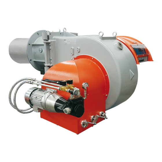
ITALIANO DESCRIZIONE COMPONENTI Testa di combustione Guarnizione Flangia attacco bruciatore Valvola a farfalla modulazione erogazione gas Servomotore regolazione gas / gasolio Display apparecchiatura Pressostato aria Servomotore regolazione aria Quadro elettrico Cerniera 17 5 22 Motore ventola Convogliatore aria in aspirazione Motore pompa Regolatore di portata combustibile liquido Elettravalvola gasolio mandata... -
Page 11: Caratteristiche Costruttive
Il bruciatore non deve operare al di fuori del TBML 1200 ME campo di lavoro dato. Potenza minima regolabile a gasolio. PERICOLO / ATTENZIONE Durante la fase di accensione e regolazione,... -
Page 12: Dimensioni Di Ingombro
ITALIANO DIMENSIONI DI INGOMBRO ØF ØG ØL ØN ØI Modello TBML 1200 ME 1650 1130 2285 Modello Ø E Ø F Ø G TBML 1200 ME DN100 Modello Ø L Ø M Ø N TBML 1200 ME Modello TBML 1200 ME... -
Page 13: Applicazione Del Bruciatore Alla Caldaia
ITALIANO APPLICAZIONE DEL BRUCIATORE ALLA CALDAIA Accertarsi che la testa di combustione penetri nel focolare nella misura richiesta dal costruttore della caldaia. Per la movimentazione del bruciatore, utilizzare catene o funi certifica- te e adeguate al peso del bruciatore utilizzando i punti di ancoraggio (21). -
Page 14: Schema Di Principio Rampa Gas
Valvola gas di lavoro con regolatore di chiusa) pressione Valvola di non ritorno Manometro 0 ÷ 40 bar Dispositivo controllo tenuta valvole (inte- Limite di fornitura Baltur Pompa bruciatore (27 bar) grato nell'apparecchiatura) A cura dell'installatore Motore pompa Valvola gas di sicurezza... -
Page 15: Schema Di Principio Per Il Collegamento Di Un Bruciatore Alla Rete Gas A Media Pressione
ITALIANO SCHEMA DI PRINCIPIO PER IL COLLEGAMENTO DI UN BRUCIATORE ALLA RETE GAS A MEDIA PRESSIONE SCHEMA DI PRINCIPIO PER IL COLLEGAMENTO DI PIÙ BRUCIATORI ALLA RETE GAS A MEDIA PRESSIONE Centralina di riduzione e misura Valvola a sfera Rubinetto di intercettazione Riduttore o regolatore/stabilizzatore di pressione (adatto al caso specifico) Filtro gas... -
Page 16: Collegamenti Elettrici
ITALIANO COLLEGAMENTI ELETTRICI • Tutti i collegamenti devono essere eseguiti con filo elettrico flessi- bile. • Le sezioni dei conduttori non specificati sono da considerarsi di 0,75 mm². • Le linee elettriche devono essere distanziate dalle parti calde. • L’installazione del bruciatore è consentita solo in ambienti con grado di inquinamento 2 come indicato nella norma EN 60204-1. -
Page 17: Impianto Di Alimentazione Con Combustibile Liquido
ITALIANO IMPIANTO DI ALIMENTAZIONE CON partenza del bruciatore e fermata all'arresto dello stesso. Il collegamento elettrico della pompa ausiliaria si realizza collegando COMBUSTIBILE LIQUIDO la bobina (230V) che comanda il teleruttore della pompa stessa, ai morsetti "N" (morsettiera ingresso linea della apparecchiatura) e "L1" La pompa del bruciatore deve ricevere il combustibile da un adatto cir- (a valle del teleruttore del motore). -
Page 18: Descrizione Del Funzionamento Con Combustibile Liquido
ITALIANO DESCRIZIONE DEL FUNZIONAMENTO CON COMBUSTIBILE LIQUIDO Il bruciatore è a funzionamento completamente automatico; chiuden- do l’interruttore generale e quello del quadro di comando il bruciatore viene inserito. Il funzionamento del bruciatore viene gestito dall'apparecchiatura elettronica di comando e controllo. La posizione di “blocco”... -
Page 19: Accensione E Regolazione Combustibile Liquido
ITALIANO ACCENSIONE E REGOLAZIONE COMBUSTIBILE LIQUIDO • Effettuare prima l’accensione con il combustibile gassoso e succes- sivamente con il combustibile liquido. PERICOLO / ATTENZIONE Durante la fase di accensione e regolazione, verificare che le potenze massima e minima a cui viene regolato il bruciatore si trovino all'interno del campo di lavoro onde evitare danni all'im- pianto. - Page 20 ITALIANO SENSORE FIAMMA La fotocellula è il dispositivo di controllo fiamma, e deve quindi essere in grado di intervenire se, durante il funzionamento, la fiamma si do- vesse spegnere (questo controllo deve essere effettuato dopo almeno un minuto dalla avvenuta accensione). Il valore della corrente della fotocellula per assicurare il funzionamento dell’apparecchiatura è...
-
Page 21: Lancia Ad Atomizzazione Meccanica
ITALIANO LANCIA AD ATOMIZZAZIONE MECCANICA La lancia ad atomizzazione meccanica è adatta all'utilizzo di gasolio. E' stata progettata per funzionare con atomizzazione tramite un disco (1) e chiusura con uno spillo (2). La molla posta sull'asta di azionamento spinge lo spillo in posizione chiusa, garantendo lo spegnimento. - Page 22 ITALIANO CONNESSIONI Le connessioni sul blocco della lancia sono contrassegnati come se- gue: S: ingresso alla lancia del gasolio di dimensione 3/8". La pressione deve essere mantenuta oltre i 20 bar. MS: attacco da 1/8" per manometro per misura della pressione in ingresso lancia.
- Page 23 ITALIANO MANUTENZIONE • Fissare in posizione il nuovo spillo con lo stesso perno; Danni ed usura dei componenti possono essere causati dal tipo di • Per controllare di aver inserito correttamente i componenti, inserire combustibile che viene utilizzato. l’asta di movimentazione all’interno della lancia senza posizionare I componenti maggiormente soggetti ad usura sono gli o-ring.
- Page 24 ITALIANO SW. 32 1) O-ring 12,42x1,78 9) Supporto 2) O-ring 18,72x2,62 10) Solenoide 3) O-ring 6,02x2,62 11) Disco 4) O-ring 2,57x1,78 12) Tappo 5) Bobina 13 Attacco manometro 6) Blocco di controllo 14) Elettrovalvola 7) Pistone A) Ritorno 8) Boccola B) Mandata 22 / 46 0006160318_202106...
- Page 25 ITALIANO POMPA BALTUR MODELLO BT Aspirazione Attacco vuotometro (1/4") Ritorno Targa pompa Mandata (ugello) Attacco manometro 1/4" Sede elemento scaldante Regolazione pressione pompa 23 / 46 0006160318_202106...
-
Page 26: Descrizione Del Funzionamento Con Combustibile Gassoso
ITALIANO DESCRIZIONE DEL FUNZIONAMENTO CON camente provvede ad adeguare l'erogazione di combustibile e aria comburente inserendo i relativi servomotori. COMBUSTIBILE GASSOSO Il bruciatore riesce così ad ottimizzare la richiesta di calore da fornire alla caldaia. Il bruciatore è a funzionamento completamente automatico; chiuden- do l’interruttore generale e quello del quadro di comando il bruciatore viene inserito. -
Page 27: Accensione E Regolazione Gas Metano
ITALIANO ACCENSIONE E REGOLAZIONE GAS METANO PERICOLO / ATTENZIONE Durante la fase di accensione e regolazione, verificare che le potenze massima e minima a cui viene regolato il bruciatore si trovino all'interno del campo di lavoro onde evitare danni all'im- pianto. - Page 28 ITALIANO PERDITE IN TESTA LATO GAS TBML 2000 ME • Durante la fase di definizione della curva di modulazione è possibi- le avere una stima approssimata della portata termica erogata nei punti intermedi mediante la misura della pressione netta del gas nellla testa di combustione.
- Page 29 ITALIANO • Il pressostato aria ha lo scopo di impedire l’apertura delle valvole del bruciatore. gas se la pressione dell’aria non è quella prevista. Il pressostato Il pressostato di minima interviene arrestando il bruciatore che rimane deve essere regolato per intervenire chiudendo il contatto quando in stand-by fino a quando la pressione si è...
-
Page 30: Manutenzione
ITALIANO MANUTENZIONE Effettuare almeno una volta all’anno e comunque in conformità alle norme vigenti, l’analisi dei gas di scarico della combustione verificando la correttezza dei valori di emissioni. • Pulire le serrande aria, il pressostato aria con presa di pressione ed il relativo tubo se presenti. -
Page 31: Tempi Di Manutenzione
ITALIANO TEMPI DI MANUTENZIONE Descrizione particolare Azione da eseguire Gasolio TESTA DI COMBUSTIONE CONTROLLO VISIVO, INTEGRITA' CERAMICHE, SMERIGLIATURA ESTREMITA', VERIFICARE ELETTRODI ANNUO ANNUO DISTANZA, VERIFICARE CONNESSIONE ELETTRICA DISCO FIAMMA CONTROLLO VISIVO INTEGRITA' EVENTUALI DEFORMAZIONI, PULIZIA ANNUO ANNUO COMPONENTI TESTA COMBUSTIONE CONTROLLO VISIVO INTEGRITA' EVENTUALI DEFORMAZIONI, PULIZIA ANNUO ANNUO... -
Page 32: Vita Attesa
ITALIANO VITA ATTESA La vita attesa dei bruciatori e dei relativi componenti dipende molto dal tipo di applicazione su cui il bruciatore è installato, dai cicli, dalla potenza erogata, dalle condizioni dell’ambiente in cui si trova, dalla frequenza e modalità di manutenzione, ecc. ecc. Le normative relative ai componenti di sicurezza prevedono una vita attesa di progetto espressa in cicli e/o anni di funzionamento. -
Page 33: Istruzioni Per L'accertamento Delle Cause Di Irregolarità Nel Funzionamento E La Loro Eliminazione
ITALIANO ISTRUZIONI PER L'ACCERTAMENTO DELLE CAUSE DI IRREGOLARITÀ NEL FUNZIONAMENTO E LA LORO ELIMINAZIONE IRREGOLARITÁ POSSIBILE CAUSA RIMEDIO 1 Termostati (caldaia o ambiente) o presso- stati, aperti. 1 Alzare il valore dei termostati oppure attende- 2 Fotoresistenza in corto circuito. re che si chiudano i contatti per diminuzione 3 Mancanza di tensione in linea, interruttore naturale della temperatura o pressione. - Page 34 ITALIANO IRREGOLARITÁ POSSIBILE CAUSA RIMEDIO 1 Temperatura di esercizio della caldaia troppo bassa (inferiore al punto di rugia- 1 Aumentare la temperatura di esercizio. da). Corrosioni interne nella caldaia. 2 Aumentare la portata di gasolio se la caldaia 2 Temperatura dei fumi troppo bassa, lo consente.
- Page 35 ITALIANO IRREGOLARITÁ POSSIBILE CAUSA RIMEDIO 1 Regolare. 1 La pressione della pompa non è regolare. 2 Scaricare l'acqua dalla cisterna servendosi L’apparecchio va in blocco spruz- 2 Presenza di acqua nel combustibile. di una pompa adatta. Non usare mai per zando combustibile liquido senza il 3 Eccesso di aria comburente.
-
Page 36: Schemi Elettrici
ITALIANO SCHEMI ELETTRICI TBML 1200ME - 1600ME - 2000ME BT 335 34 / 46 0006160318_202106... - Page 37 ITALIANO TBML 1200ME - 1600ME - 2000ME BT 335 35 / 46 0006160318_202106...
- Page 38 ITALIANO TBML 1200ME - 1600ME - 2000ME BT 335 36 / 46 0006160318_202106...
- Page 39 ITALIANO TBML 1200ME - 1600ME - 2000ME BT 335 37 / 46 0006160318_202106...
- Page 40 ITALIANO TBML 1200ME - 1600ME - 2000ME BT 335 38 / 46 0006160318_202106...
- Page 41 ITALIANO APPARECCHIATURA GNYE VERDE / GIALLO SENSORE FIAMMA SONDA ATTIVA GRIGIO SONDA DI PRESSIONE BRUNO SONDA DI TEMPERATURA NERO SONDA DI TEMPERATURA ACQUA CONNETTORE NERO CON SOVRASTAMPA SONDA DI TEMPERATURA ESTERNA L1 - L2- L3 Fasi N - Neutro RELE’ TERMICO ** Solo per taratura RELE’...
-
Page 42: Schemi Elettrici
ITALIANO SCHEMI ELETTRICI TBML 1200 - 1600 - 2000 ME 40 / 46 0006160318_202106... - Page 43 ITALIANO TBML 1200 - 1600 - 2000 ME 41 / 46 0006160318_202106...
- Page 44 ITALIANO TBML 1200 - 1600 - 2000 ME 42 / 46 0006160318_202106...
- Page 45 ITALIANO TBML 1200 - 1600 - 2000 ME 43 / 46 0006160318_202106...
- Page 46 ITALIANO TBML 1200 - 1600 - 2000 ME 44 / 46 0006160318_202106...
- Page 47 ITALIANO APPARECCHIATURA ELETTROVALVOLA DI SICUREZZA RAMPA PILOTA APPARECCHIATURA PER DUE COMBUSTIBILI ELETTROVALVOLA DI SICUREZZA MANDATA SENSORE FIAMMA ELETTROVALVOLA DI SICUREZZA RITORNO SONDA ATTIVA Colore serie fili GNYE VERDE / GIALLO SONDA DI PRESSIONE SONDA DI TEMPERATURA GRIGIO SONDA DI TEMPERATURA ACQUA BRUNO SONDA DI TEMPERATURA ESTERNA NERO...
- Page 48 ITALIANO 46 / 46 0006160318_202106...
- Page 49 ENGLISH ENGLISH SUMMARY Warnings for use in safety conditions ..................................2 Technical specifications ......................................6 Standard accessories .......................................6 Burner identification plate ....................................7 Data recorded during first start-up ..................................7 Component description ....................................8 Design characteristics ......................................9 Technical functional characteristics ..................................9 Operating range .......................................9 Overall dimensions ......................................10 Burner connection to the boiler .....................................
-
Page 50: Warnings For Use In Safety Conditions
ENGLISH WARNINGS FOR USE IN SAFETY • The equipment use is allowed to such people only if they can have access to, through a responsible person, the information concerning CONDITIONS their safety, surveillance and instructions concerning equipment use. • Children must be watched over to prevent them from playing with PURPOSE OF THIS MANUAL the equipment. - Page 51 - At the end of the adjustment procedures, check that all the with it directly. Contact only qualified personnel. locking devices of mechanical securing systems are properly • Any product repairs must only be carried out by BALTUR authorised tightened. assistance centres or by its local distributor using only original spare - Make sure that the use and maintenance manual of the burner is parts.
- Page 52 ENGLISH SPECIAL PRECAUTIONS WHEN USING GAS. replace it contact qualified personnel only; • Check that the feed line and the train comply with current law and - If you decide not to use the equipment for a certain period of time regulations.
- Page 53 ENGLISH TO BE CARRIED OUT BY THE INSTALLER - The emergency activation device must be clearly visible and • Install a suitable disconnecting switch for each burner supply line. easily reachable and actionable in the immediate vicinity of the • The disconnection must be carried out by means of a device com- burner.
-
Page 54: Technical Specifications
ENGLISH TECHNICAL SPECIFICATIONS MODEL TBML 1200 ME Maximum natural gas thermal power 12000 Minimum natural gas thermal power 1500 mg/kWh ¹) natural gas emissions Class 3 Natural gas operation Electronic modulation Stm³/h Maximum natural gas thermal rate 1270 Stm³/h Minimum natural gas thermal rate... -
Page 55: Burner Identification Plate
ENGLISH ¹) NATURAL GAS EMISSIONS ³) DIESEL EMISSIONS Classes defined according to EN 676 standards. Classes defined according to EN 267 standards. Class NOx emissions in mg/kWh natural gas NOx emissions in mg/kWh diesel CO emissions in mg/kWh diesel Class ≤... -
Page 56: Component Description
ENGLISH COMPONENT DESCRIPTION Combustion head Seal Burner connection flange Gas supply control butterfly valve Gas / diesel regulator servomotor Device display Air pressure switch Air regulation servomotor Electrical panel Hinge 17 5 22 Fan motor Intake air conveyor Pump motor Liquid fuel flow rate regulator Diesel delivery solenoid valve Liquid fuel pressure switch... -
Page 57: Design Characteristics
The burner shall not operate outside its spe- cific operating range. Minimum power adjustable with diesel. TBML 1200 ME DANGER / ATTENTION During the ignition and adjustment pha- se, check that the maximum and minimum... -
Page 58: Overall Dimensions
ENGLISH OVERALL DIMENSIONS ØF ØG ØL ØN ØI Model TBML 1200 ME 1650 1130 2285 Model Ø E Ø F Ø G TBML 1200 ME DN100 Model Ø L Ø M Ø N TBML 1200 ME Model TBML 1200 ME... -
Page 59: Burner Connection To The Boiler
ENGLISH BURNER CONNECTION TO THE BOILER Make sure that the combustion head penetrates into the furnace to the extent requested by the boiler manufacturer. For burner handling, use certified chains or ropes suitable for the bur- ner weight using the anchoring points (21). Anchor the burner to the boiler as follows: •... -
Page 60: Gas Train Block Diagram
Pressure gauge 0 - 40 bar Non-return valve Valve tightness control device (integrated Burner pump (27 bar) into the equipment) Baltur supply limit Pump motor Safety gas valve To be carried out by the installer Flexible hose Minimum gas pressure switch and gas... -
Page 61: Block Diagram For Connection Of One Burner To The Medium Pressure Gas Supply Network
ENGLISH BLOCK DIAGRAM FOR CONNECTION OF ONE BURNER TO THE MEDIUM PRESSURE GAS SUPPLY NETWORK BLOCK DIAGRAM FOR CONNECTING MORE BURNERS TO THE MEDIUM PRESSURE GAS SUPPLY NETWORK Reduction and measurement control unit Ball valve Shut-off cock Pressure reducer or regulator/stabilizer (suitable for the specific case) Gas filter Vibration-proof joint Pressure reducer... -
Page 62: Electrical Connections
ENGLISH ELECTRICAL CONNECTIONS • It is advisable to make all connections with flexible electric wire. • Conductor cross-sections not specified are to be considered as 0,75 mm². • The power lines must be distanced from the hot parts. • The burner can be installed exclusively in environments with pollu- tion degree 2 as specified in Standard EN 60204-1. -
Page 63: Liquid Fuel Supply System
ENGLISH LIQUID FUEL SUPPLY SYSTEM • The auxiliary pump must be installed as close as possible to the liquid to be sucked. The burner pump must receive the fuel from a suitable supply circuit • The head must be suitable for the relative plant. featuring an auxiliary pump which may feature a pressure regulator •... -
Page 64: Description Of Operation With Liquid Fuel
ENGLISH DESCRIPTION OF OPERATION WITH LIQUID FUEL The burner operates fully automatically: it is activated by switching on the main switch and the control panel switch. Burner operation is managed by command and control electronic de- vices. The “lock-out” position is a safety position that the burner automati- cally assumes when a burner or system component is not working properly. -
Page 65: Ignition And Adjustment With Liquid Fuel
ENGLISH IGNITION AND ADJUSTMENT WITH LIQUID FUEL • First ignite with gaseous fuel and then later with liquid fuel. DANGER / ATTENTION During the ignition and adjustment phase, check that the maxi- mum and minimum outputs at which the burner is adjusted are within the working range in order to avoid damage to the system. - Page 66 ENGLISH FLAME SENSOR The flame detecting UV photocell must be able to trigger upon system operation if the flame turns off (this check must be carried out after at least one minute from the ignition). The photocell current value required for a correct operation of the equi- pment is indicated in the wiring diagram.
-
Page 67: Lance For Mechanical Spraying
ENGLISH LANCE FOR MECHANICAL SPRAYING The lance for mechanical spraying is suitable for use with diesel. It was designed to operate by spraying through a disk (1) and closing with a pin (2). The spring on the activating rod pushes the pin in the closing position, ensuring the turning off. - Page 68 ENGLISH CONNECTIONS The connections on the lance block are marked as follows: S: 3/8” inlet to diesel lance. The pressure must be kept over 20 bar. MS: 1/8" connection for the pressure gauge detecting lance input pressure. R: 3/8” fuel return pipe. MR: connection for the pressure gauge detecting return pressure.
- Page 69 ENGLISH MAINTENANCE • Fix the new pin in position with the same fastener; Damage and wear of components may be caused by the type of fuel • To check whether all components have been fitted correctly, insert used. the handling rod inside the lance without positioning the O-rings (1) The components most subjected to wear are the O-rings.
- Page 70 ENGLISH SW. 32 1) 12.42x1.78 O-ring 9) Support 2) 18.72x2.62 O-ring 10) Solenoid 3) 6.02x2.62 O-ring 11) Disk 4) 2.57x1.78 O-ring 12) Cap 5) Coil 13) Pressure gauge connection 6) Control block 14) Solenoid valve 7) Piston A) Return 8) Bush B) Delivery 22 / 46 0006160318_202106...
- Page 71 ENGLISH BALTUR PUMP BT MODEL Aspirazione Vacuum gauge connection (1/4") Ritorno Pump data plate Delivery (nozzle) Pressure gauge 1/4” connection Heating element seat 8_tab_Pump pressure regulation 23 / 46 0006160318_202106...
-
Page 72: Operation Description With Gaseous Fuel
ENGLISH OPERATION DESCRIPTION WITH GASEOUS FUEL The burner operates fully automatically: it is activated by switching on the main switch and the control panel switch. Burner operation is managed by command and control electronic de- vices. Blown air burners with electronic modulation may be used on hearths under strong pressure or in a vacuum, according to the corresponding operating curves. -
Page 73: Natural Gas Ignition And Regulation
ENGLISH NATURAL GAS IGNITION AND REGULATION DANGER / ATTENTION During the ignition and adjustment phase, check that the ma- ximum and minimum outputs at which the burner is adjusted are within the working range in order to avoid damage to the system. - Page 74 ENGLISH HEAD LOSSES ON GAS SIDE TBML 2000 ME • Upon defining the modulation curve, it is possible to have an ap- proximate estimate of the thermal flow rate delivered at the inter- mediate points be measuring the gas pressure in the combustion head.
- Page 75 ENGLISH • The air pressure switch prevents the opening of the gas valves if ning (flame on), locks out the burner immediately. the air pressure is not the foreseen one. The pressure switch must The minimum value pressure switch stops the burner that remains be adjusted to intervene closing the contact when the air pressure on standby until the pressure is restored within the values required in the burner reaches a sufficient value.
-
Page 76: Maintenance
ENGLISH MAINTENANCE Analyse combustion gases and check that the emission values are correct at least once a year, in compliance with current law. • Clean air dampers, the air pressure switch with pressure port and the relevant pipe, if any. •... -
Page 77: Maintenance Time
ENGLISH MAINTENANCE TIME Part description Action to be performed Diesel COMBUSTION HEAD VISUAL INSPECTION OF THE INTEGRITY OF CERAMICS. TIP GRINDING, CHECK DISTANCE, ELECTRODES YEARLY YEARLY CHECK ELECTRICAL CONNECTION FLAME DISC INTEGRITY VISUAL CHECK FOR ANY DEFORMATIONS, CLEANING, YEARLY YEARLY COMBUSTION HEAD COMPONENTS INTEGRITY VISUAL CHECK FOR ANY DEFORMATIONS, CLEANING, YEARLY... -
Page 78: Expected Lifespan
ENGLISH EXPECTED LIFESPAN The expected lifespan of burners and relevant components depends very much from the type of application on which the burner is installed, from cycles ,of delivered power, from the conditions of the environment in which it is located, from maintenance frequency and mode, etc. Standards about safety components provide for a project expected lifespan expressed in cycles and/or years of operation. -
Page 79: Instructions For Determining The Cause Leading To Irregularities In The Operation And Their Elimination
ENGLISH INSTRUCTIONS FOR DETERMINING THE CAUSE LEADING TO IRREGULARITIES IN THE OPERATION AND THEIR ELIMINATION IRREGULARITY POSSIBLE CAUSE REMEDY 1 Thermostats (boiler or room) or pressure switches are open. 1 Raise the thermostats settings, or wait that 2 Photoresistor in short circuit. the contacts close for natural decrease of The burner does not start.(The 3 Absence of line voltage, main switch open,... - Page 80 ENGLISH IRREGULARITY POSSIBLE CAUSE REMEDY 1 Boiler operating temperature too low 1 Increase the operating temperature. (below the dew point). Corrosion inside the boiler. 2 Increase diesel flow rate is the boiler allows 2 Smoke temperature too low, approxima- tely below 130 °C for diesel. 1 Excessive cooling of smoke (approxi- mately below 130°C) in the chimney, for 1 Improve insulation and close any opening...
- Page 81 ENGLISH IRREGULARITY POSSIBLE CAUSE REMEDY 1 Adjust. 1 Pump pressure is not regular. 2 Drain water from the tank using a suitable 2 Water in the fuel. pump. Never use the burner pump for this The burner goes into lock-out 3 Too much combustion air.
-
Page 82: Wiring Diagrams
ENGLISH WIRING DIAGRAMS TBML 1200ME - 1600ME - 2000ME BT 335 34 / 46 0006160318_202106... - Page 83 ENGLISH TBML 1200ME - 1600ME - 2000ME BT 335 35 / 46 0006160318_202106...
- Page 84 ENGLISH TBML 1200ME - 1600ME - 2000ME BT 335 36 / 46 0006160318_202106...
- Page 85 ENGLISH TBML 1200ME - 1600ME - 2000ME BT 335 37 / 46 0006160318_202106...
- Page 86 ENGLISH TBML 1200ME - 1600ME - 2000ME BT 335 38 / 46 0006160318_202106...
- Page 87 ENGLISH CONTROL BOX GNYE GREEN / YELLOW Flame sensor BLUE ACTIVE PROBE GREY PRESSURE PROBE BROWN TEMPERATURE PROBE BLACK WATER TEMPERATURE PROBE BLACK CONNECTOR WITH OVERPRINT EXTERNAL TEMPERATURE PROBE L1 - L2- L3 Phases N - Neutral THERMAL RELAY ** For calibration only PUMP THERMAL RELAY FU1÷4 FUSES SPRAY NOZZLE UNIT...
-
Page 88: Wiring Diagrams
ENGLISH WIRING DIAGRAMS TBML 1200 - 1600 - 2000 ME 40 / 46 0006160318_202106... - Page 89 ENGLISH TBML 1200 - 1600 - 2000 ME 41 / 46 0006160318_202106...
- Page 90 ENGLISH TBML 1200 - 1600 - 2000 ME 42 / 46 0006160318_202106...
- Page 91 ENGLISH TBML 1200 - 1600 - 2000 ME 43 / 46 0006160318_202106...
- Page 92 ENGLISH TBML 1200 - 1600 - 2000 ME 44 / 46 0006160318_202106...
- Page 93 ENGLISH CONTROL BOX PILOT TRAIN SAFETY SOLENOID VALVE DUAL FUEL EQUIPMENT DELIVERY SAFETY SOLENOID VALVE Flame sensor RETURN SAFETY SOLENOID VALVE ACTIVE PROBE Wire series colour GNYE GREEN / YELLOW PRESSURE PROBE BLUE TEMPERATURE PROBE GREY WATER TEMPERATURE PROBE BROWN EXTERNAL TEMPERATURE PROBE BLACK THERMAL RELAY...
- Page 94 ENGLISH 46 / 46 0006160318_202106...
- Page 96 BALTUR S.P.A. Via Ferrarese, 10 44042 Cento (Fe) - Italy Tel. +39 051-6843711 Fax. +39 051-6857527/28 www.baltur.it info@baltur.it Il presente catalogo riveste carattere puramente indicativo. La casa, pertanto, si riserva ogni possibilità di modifica dei dati tecnici e di quant'altro in esso riportato.
Need help?
Do you have a question about the TBML 1200 ME and is the answer not in the manual?
Questions and answers