Table of Contents
Advertisement
Available languages
Available languages
Quick Links
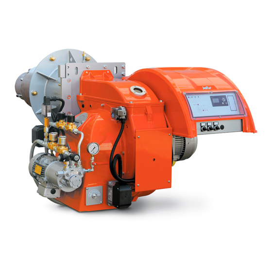
BRUCIATORE MISTO GAS / GASOLIO A MODULAZIONE
ELETTRONICA CON APPARECCHIATURA BT 340
ELECTRONIC MODULATING DUAL FUEL GAS/DIESEL BURNER
WITH BT 340 EQUIPMENT
ITALIANO
TBML 350 ME
Manuale istruzioni per l'installazione, l'uso e la
IT
manutenzione
Installation, use and maintenance instruction
EN
manual
ISTRUZIONI ORIGINALI (IT)
ORIGINAL INSTRUCTIONS (IT)
0006160077_201802
Advertisement
Table of Contents

Related Manuals for baltur TBML 350 ME


Summary of Contents for baltur TBML 350 ME
- Page 1 BRUCIATORE MISTO GAS / GASOLIO A MODULAZIONE ELETTRONICA CON APPARECCHIATURA BT 340 ELECTRONIC MODULATING DUAL FUEL GAS/DIESEL BURNER WITH BT 340 EQUIPMENT ITALIANO TBML 350 ME Manuale istruzioni per l'installazione, l'uso e la manutenzione Installation, use and maintenance instruction manual...
-
Page 3: Table Of Contents
ITALIANO ITALIANO SOMMARIO Avvertenze per l'uso in condizioni di sicurezza ..............................3 Caratteristiche tecniche ...................................... 6 Materiale a corredo ...................................... 7 Targa identificazione bruciatore ................................... 7 Dati registrazione prima accensione ................................7 Caratteristiche costruttive .................................... 8 Campo di lavoro ......................................8 Caratteristiche tecnico funzionali ................................. - Page 4 ITALIANO DICHIARAZIONE DI CONFORMITÀ CE0085: DVGW CERT GmbH, Josef-Wirmer Strasse 1-3-53123 Bonn (D) Dichiariamo che i nostri bruciatori ad aria soffiata di combustibili luquidi, gassosi e misti, domestici e industriali, serie: BPM...; BGN…; BT…; BTG…; BTL…; TBML...; Comist…; GI…; GI…Mist; Minicomist…; PYR…; RiNOx…; Spark...; Sparkgas...; TBG...;TBL...; TS…;...
-
Page 5: Avvertenze Per L'uso In Condizioni Di Sicurezza
ITALIANO AVVERTENZE PER L'USO IN CONDIZIONI DI compresi) le cui capacità fisiche, sensoriali o mentali siano ridotte, oppure con mancanza di esperienza o di conoscenza. SICUREZZA • l'uso dell'apparecchio è consentito a tali persone solo nel caso in cui possano beneficiare, attraverso l'intermediazione di una SCOPO DEL MANUALE persona responsabile, di informazioni relative alla loro sicurezza, Il manuale si propone di contribuire all'utilizzo sicuro del prodotto... - Page 6 • Prima di avviare il bruciatore e almeno una volta all’anno, far • L’eventuale riparazione dei prodotti dovrà essere effettuata effettuare da personale professionalmente qualificato le seguenti solamente da un centro di assistenza autorizzato da BALTUR o dal operazioni: suo distributore locale, utilizzando esclusivamente ricambi originali.
- Page 7 ITALIANO Avvertenze particolari per l’uso del gas. • L’alimentazione elettrica del bruciatore deve prevedere il neutro a • Verificare che la linea di adduzione e la rampa siano conformi alle terra. In caso di controllo della corrente di ionizzazione con neutro norme e prescrizioni vigenti.
-
Page 8: Caratteristiche Tecniche
ITALIANO CARATTERISTICHE TECNICHE MODELLO TBML 350 ME POTENZA TERMICA MAX METANO 3600 POTENZA TERMICA MIN METANO mg/kWh ¹) EMISSIONI METANO Classe 3 FUNZIONAMENTO METANO modulazione Elettronica Stm³/h PORTATA TERMICA MAX METANO Stm³/h PORTATA TERMICA MIN METANO hPa (mbar) PRESSIONE MIN METANO... -
Page 9: Materiale A Corredo
ITALIANO MATERIALE A CORREDO MODELLO TBML 350 ME GUARNIZIONE ISOLANTE PRIGIONIERI N°6 - M20 DADI ESAGONALI N°6 - M20 RONDELLE PIANE N°6 - Ø20 TUBI FLESSIBILI N°2 - 1"1/4 x 1"1/4 FILTRO N°1 - 1"1/4 ³) EMISSIONI GASOLIO ¹) EMISSIONI GAS METANO ²) EMISSIONI GAS PROPANO... -
Page 10: Caratteristiche Costruttive
ITALIANO CARATTERISTICHE COSTRUTTIVE CARATTERISTICHE TECNICO FUNZIONALI Il bruciatore risulta composto da: • Bruciatore misto in grado di funzionare alternativamente a gas • Parte ventilante in lega leggera d'alluminio. naturale oppure a gasolio (viscosità max 1.5° E a 20° C). • Ventilatore centrifugo per alte prestazioni. •... -
Page 11: Descrizione Componenti
ITALIANO DESCRIZIONE COMPONENTI Testa di combustione Guarnizione Flangia attacco bruciatore Valvola farfalla gas Servomotore regolazione gas / gasolio Display apparecchiatura Pressostato aria Servomotore regolazione aria Quadro elettrico Cerniera Motore ventola Convogliatore aria in aspirazione Regolatore di portata gasolio Elettrovalvola gasolio ritorno Pressostato gasolio Flangia attacco rampa gas Pompa combustibile liquido... -
Page 12: Dimensioni Di Ingombro
ITALIANO DIMENSIONI DI INGOMBRO Modello TBML 350 ME 1616 599.5 1853 Modello Ø E Ø F Ø L Ø N TBML 350 ME Modello TBML 350 ME 1182 10 / 44 0006160077_201802... -
Page 13: Applicazione Del Bruciatore Alla Caldaia
ITALIANO APPLICAZIONE DEL BRUCIATORE ALLA CALDAIA MONTAGGIO GRUPPO TESTATA Accertarsi che la testa di combustione penetri nel focolare nella misura richiesta dal costruttore della caldaia. Prima di installare il bruciatore alla caldaia, accertarsi che l'ugello sia adeguato alla potenza richiesta. Per movimentare il bruciatore si consiglia di agganciare ai golfari una adeguata attrezzatura di sollevamento. -
Page 14: Montaggio Gruppo Cerniera A Destra O Sinistra
ITALIANO MONTAGGIO GRUPPO CERNIERA A DESTRA O SINISTRA Il bruciatore è dotato di cerniera ambidestra, quindi è possibile invertire il lato di apertura del corpo ventilante. Il bruciatore viene fornito di serie con cerniera montata sul lato sinistro. Per consentire l’apertura massima e facilitare quindi le operazioni di manutenzione, si consiglia di disporre la cerniera sul lato opposto del bruciatore rispetto alla posizione in cui è... -
Page 15: Schema Di Principio Rampa Gas
Filtro combustibile liquido Valvola gas fiamma principale Servomotore regolazione gas / gasolio Pressostato gasolio di massima Dispositivo controllo tenuta valvole Regolatore di portata ritorno gasolio Limite fornitura baltur (integrato nell'apparecchiatura) e relativo A cura dell'installatore Elettrovalvole gasolio mandata pressostato Ritorno combustibile dall'ugello... -
Page 16: Schema Di Principio Per Il Collegamento Di Più Bruciatori Alla Rete Gas A Media Pressione
ITALIANO SCHEMA DI PRINCIPIO PER IL COLLEGAMENTO DI PIÙ BRUCIATORI ALLA RETE GAS A MEDIA PRESSIONE Centralina di riduzione e misura Rubinetto a sfera Rubinetto di intercettazione Filtro gas Filtro gas Riduttore o regolatore/stabilizzatore di pressione (adatto al caso specifico) Riduttore di pressione Giunto antivibrante Contatori... -
Page 17: Collegamenti Elettrici
ITALIANO COLLEGAMENTI ELETTRICI POMPA AUSILIARIA In alcuni casi (eccessiva distanza o dislivello) è necessario effettuare • Tutti i collegamenti devono essere eseguiti con filo elettrico l'impianto con un circuito di alimentazione ad "anello", con pompa flessibile. ausiliaria, evitando quindi il collegamento diretto della pompa del •... -
Page 18: Impianto Di Alimentazione Con Combustibile Liquido
ITALIANO IMPIANTO DI ALIMENTAZIONE CON COMBUSTIBILE LIQUIDO La pompa del bruciatore deve ricevere il combustibile da un adatto circuito di alimentazione con pompa ausiliaria, eventualmente provvisto di regolatore di pressione regolabile da 0,5 a 3 bar. Il valore della pressione di alimentazione del combustibile alla pompa del bruciatore non deve variare sia con bruciatore fermo che con bruciatore funzionante alla massima erogazione di combustibile richiesta dalla caldaia. -
Page 19: Descrizione Del Funzionamento
ITALIANO DESCRIZIONE DEL FUNZIONAMENTO PRECISAZIONE PER L'ACCENSIONE DEL BRUCIATORE MISTO Si consiglia di effettuare prima l'accensione con combustibile liquido (selettore 2 in posizione OIL, accensione led OIL) perchè l'erogazione è, in questo caso, condizionata dall'ugello utilizzato, mentre l'erogazione del gas metano può essere variata a piacere agendo sul relativo regolatore di portata. -
Page 20: Accensione E Regolazione Combustibile Liquido
ITALIANO ACCENSIONE E REGOLAZIONE COMBUSTIBILE LIQUIDO Si consiglia di effettuare prima l’accensione con il combustibile liquido in quanto l’erogazione è condizionata dall’ugello. Successivamente per la regolazione a gas agire sullo stabilizzatore di pressione della rampa gas. • Portare l’interruttore, posto sul quadro di comando, nella posizione “O”... - Page 21 ITALIANO SCHEMA COLLEGAMENTO POMPA HP MODELLO VBH • Quando il bruciatore è in funzione al “minimo”, regolare l’aria ed il combustibile liquido nelle quantità necessarie per assicurare una buona combustione. Per il funzionamento a gasolio impiegare ugelli modello BERGONZO tipo B5 45° senza spillo a seconda della portata termica massima regolata.
-
Page 22: Ugello Bergonzo Senza Spillo
ITALIANO UGELLO BERGONZO SENZA SPILLO Per il funzionamento a gasolio impiegare ugelli modello BERGONZO tipo B5 45° senza spillo a seconda della portata termica massima regolata. Nei grafici seguenti sono rappresentate le curve che riportano i valori della portata di combustibile erogata dagli ugelli in funzione della pressione di ritorno. - Page 23 ITALIANO 21 / 44 0006160077_201802...
- Page 24 ITALIANO 22 / 44 0006160077_201802...
- Page 25 ITALIANO 23 / 44 0006160077_201802...
- Page 26 ITALIANO 24 / 44 0006160077_201802...
- Page 27 ITALIANO 25 / 44 0006160077_201802...
- Page 28 ITALIANO 26 / 44 0006160077_201802...
- Page 29 ITALIANO 27 / 44 0006160077_201802...
-
Page 30: Accensione E Regolazione Gas Metano
ITALIANO ACCENSIONE E REGOLAZIONE GAS giorno o di una comune lampada. L’eventuale verifica di sensibilità può essere fatta con la fiamma di un accendino o di una candela. METANO Per assicurare un corretto funzionamento il valore di tensione della fotocellula deve essere sufficientemente stabile e non scendere al •... -
Page 31: Descrizione Del Funzionamento Pressostato Aria
ITALIANO • Dopo aver regolato l’aria per il minimo, salire di potenza e procedere alla definizione della curva di lavoro come indicato nel manuale dell'apparecchiatura. • Effettuare il controllo della combustione con l'apposito strumento in tutti i punti intermedi della curva di modulazione. •... -
Page 32: Descrizione Del Funzionamento Pressostato Gas
ITALIANO DESCRIZIONE DEL FUNZIONAMENTO PRESSOSTATO GAS Nel caso in cui sulla rampa gas sia montato un solo pressostato, questo sarà di minima. I pressostati di controllo della pressione del gas (minima e massima) hanno lo scopo di impedire il funzionamento del bruciatore quando la pressione del gas non risulta compresa nei valori previsti. -
Page 33: Regolazione Aria Sulla Testa Di Combustione
ITALIANO REGOLAZIONE ARIA SULLA TESTA DI COMBUSTIONE POTENZA ALL'ACCENSIONE La norma EN 676 prescrive che per i bruciatori con potenza massima oltre i 120 kW l'accensione deve avvenire ad una potenza Pstart ridotta rispetto alla potenza massima di funzionamento Pmax a cui è... -
Page 34: Manutenzione
ITALIANO MANUTENZIONE Effettuare almeno una volta all’anno e comunque in conformità alle norme vigenti, l’analisi dei gas di scarico della combustione verificando la correttezza dei valori di emissioni. • Pulire le serrande aria, il pressostato aria con presa di pressione ed il relativo tubo se presenti. -
Page 35: Tempi Di Manutenzione
ITALIANO TEMPI DI MANUTENZIONE Descrizione particolare Azione da eseguire Gasolio TESTA DI COMBUSTIONE CONTROLLO VISIVO, INTEGRITA CERAMICHE. SMERIGLIATURA ELETTRODI ESTREMITA, VERIFICARE DISTANZA, VERIFICARE CONNESSIONE ANNUO ANNUO ELETTRICA DISCO FIAMMA CONTROLLO VISIVO INTEGRITA EVENTUALI DEFORMAZIONI, PULIZIA ANNUO ANNUO CONTROLLO VISIVO, INTEGRITA CERAMICHE. SMERIGLIATURA SONDA DI IONIZZAZIONE ESTREMITA, VERIFICARE DISTANZA, VERIFICARE CONNESSIONE ANNUO... -
Page 36: Vita Attesa
ITALIANO VITA ATTESA La vita attesa dei bruciatori e dei relativi componenti dipende molto dal tipo di applicazione su cui il bruciatore è installato, dai cicli della potenza erogata, dalle condizioni dell’ambiente in cui si trova, dalla frequenza e modalità di manutenzione, ecc. ecc. Le normative relative ai componenti di sicurezza, prevedono una vita attesa di progetto espressa in cicli e/o anni di funzionamento. -
Page 37: Tabella Portata Ugelli
ITALIANO TABELLA PORTATA UGELLI Ugello Pressione Pompa bar Ugello G.P.H. G.P.H. 0,40 1,18 1,27 1,36 1,44 1,52 1,59 1,67 1,73 1,80 1,86 1,92 1,98 2,04 2,10 2,15 2,20 2,25 2,31 2,36 2,40 2,45 0,40 0,50 1,47 1,59 1,70 1,80 1,90 1,99 2,08 2,17... -
Page 38: Istruzioni Per L'accertamento Delle Cause Di Irregolarità Nel Funzionamento E La Loro Eliminazione
ITALIANO ISTRUZIONI PER L'ACCERTAMENTO DELLE CAUSE DI IRREGOLARITÀ NEL FUNZIONAMENTO E LA LORO ELIMINAZIONE IRREGOLARITÁ POSSIBILE CAUSA RIMEDIO Termostati (caldaia o ambiente) o pressostati, aperti. Alzare il valore dei termostati oppure Fotoresistenza in corto circuito. attendere che si chiudano i contatti per Mancanza di tensione in linea, diminuzione naturale della temperatura o Bruciatore... - Page 39 ITALIANO IRREGOLARITÁ POSSIBILE CAUSA RIMEDIO Temperatura di esercizio della caldaia troppo bassa (inferiore al punto di Aumentare la temperatura di esercizio. rugiada). Corrosioni interne nella caldaia. Aumentare la portata di gasolio se la Temperatura dei fumi troppo bassa, caldaia lo consente. indicativamente al di sotto dei 130°...
- Page 40 ITALIANO IRREGOLARITÁ POSSIBILE CAUSA RIMEDIO Regolare. La pressione della pompa non è Scaricare l'acqua dalla cisterna regolare. servendosi di una pompa adatta. Non L’apparecchio blocco Presenza di acqua nel combustibile. usare mai per questo lavoro la pompa spruzzando combustibile liquido Eccesso di aria comburente.
-
Page 41: Schemi Elettrici
ITALIANO SCHEMI ELETTRICI 39 / 44 0006160077_201802... - Page 42 ITALIANO 40 / 44 0006160077_201802...
- Page 43 ITALIANO 41 / 44 0006160077_201802...
- Page 44 ITALIANO 42 / 44 0006160077_201802...
- Page 45 ITALIANO 43 / 44 0006160077_201802...
- Page 46 ITALIANO ELETTROVALVOLA PRINCIPALE RITORNO APPARECCHIATURA APPARECCHIATURA PER DUE COMBUSTIBILI ELETTROVALVOLA PRINCIPALE MANDATA FOTORESISTENZA / ELETTRODO DI IONIZZAZIONE / ELETTROVALVOLA DI SICUREZZA FOTOCELLULA UV ELETTROVALVOLA DI SICUREZZA MANDATA RELE’ TERMICO ELETTROVALVOLA DI SICUREZZA RITORNO RELE’ TERMICO POMPA GNYE VERDE / GIALLO FU1÷4 FUSIBILI SPIA BLOCCO ESTERNA / LAMPADA FUNZIONAMENTO BRUNO...
- Page 47 ENGLISH ENGLISH INDEX Instructions for use in safe conditions ................................3 Technical specifications ...................................... 6 Supplied material ......................................7 Burner identification plate .................................... 7 First start up recording data ..................................7 Design characteristics ....................................8 Operating range ......................................8 Technical functional characteristics ................................8 Component description ....................................9 Overall dimensions ....................................10 Burner connection to the boiler ..................................
- Page 48 ENGLISH DECLARATION OF CONFORMITY CE0085: DVGW CERT GmbH, Josef-Wirmer Strasse 1-3-53123 Bonn (D) We hereby declare under our own responsibility, that our domestic and industrial blown air burners fired by gas, oil and dual fuel, series: BPM...; BGN…; BT…; BTG…; BTL…; TBML...; Comist…; GI…; GI…Mist; Minicomist…; PYR…; RiNOx…; Spark...; Sparkgas...; TBG...;TBL...; TS…;...
- Page 49 ENGLISH INSTRUCTIONS FOR USE IN SAFE the device. • This appliance should only be used for the purpose it has been CONDITIONS designed for. Any other use is to be considered improper and therefore dangerous. PURPOSE OF THE MANUAL • The equipment must be installed in accordance with current The manual purpose is to contribute to the safe use of the product, regulations, following the manufacturer’s instructions and by indicating the conduct and behaviour required to prevent alterations...
- Page 50 Contact only qualified personnel. - Check the regulation and safety devices are working properly. • Any product repairs must only be carried out by BALTUR authorised - Check for the correct operation of the combustion products assistance centres or its local retailer using only original spare exhaust duct.
- Page 51 ENGLISH Special instructions for using gas. • The use of any components that use electricity means that certain • Check that the feed line and the train comply with current standards fundamental rules have to followed, including the following: and regulations. - do not touch the equipment with parts of the body that are wet •...
- Page 52 ENGLISH TECHNICAL SPECIFICATIONS MODEL TBML 350 ME NATURAL GAS MAX. THERMAL POWER 3600 NATURAL GAS MIN. THERMAL POWER mg/kWh ¹) NATURAL GAS EMISSIONS Class 3 NATURAL GAS OPERATION electronic modulation Stm³/h NATURAL GAS MAX. HEATING CAPACITY Stm³/h NATURAL GAS MIN. HEATING CAPACITY hPa (mbar) NATURAL GAS MIN.
- Page 53 ENGLISH SUPPLIED MATERIAL MODEL TBML 350 ME INSULATING SEAL STUD BOLTS No. 6 - M20 HEXAGONAL NUTS No. 6 - M20 FLAT WASHERS No. 6 - Ø20 HOSES No. 2 - 1"1/4 x 1"1/4 FILTER No. 1 - 1"1/4 ³) DIESEL EMISSIONS ¹) NATURAL GAS EMISSIONS...
- Page 54 ENGLISH DESIGN CHARACTERISTICS TECHNICAL FUNCTIONAL CHARACTERISTICS The burner consists of: • Dual burner, able to operate alternately with natural gas or with • Ventilating part in light aluminium alloy. diesel (max viscosity 1.5° E at 20°C). • Centrifugal fan for high performances. •...
- Page 55 ENGLISH COMPONENT DESCRIPTION Combustion head Seal Burner connection flange Gas throttle valve Gas / diesel regulator servomotor Equipment display Air pressure switch Air regulation servomotor Electrical panel Hinge Fan motor Intake air conveyor Diesel flow rate regulator Diesel return solenoid valve Diesel pressure switch Gas train connector flange Liquid fuel pump...
- Page 56 ENGLISH OVERALL DIMENSIONS Model TBML 350 ME 1616 599.5 1853 Model Ø E Ø F Ø L Ø N TBML 350 ME Model TBML 350 ME 1182 10 / 44 0006160077_201802...
- Page 57 ENGLISH BURNER CONNECTION TO THE BOILER ASSEMBLING THE HEAD UNIT Check that combustion head penetrates the combustion chamber by the measure requested by the manufacturer of the boiler. Before installing the burner to the boiler, make sure that the nozzle is adjusted to the power required.
- Page 58 ENGLISH HINGE UNIT ASSEMBLY TO THE RIGHT OR LEFT The burner hinge can be opened both ways, it is therefore possible to reverse the opening side of the ventilating body. As a standard, the burner is supplied with the hinge installed on the left side.
- Page 59 Gas / diesel regulator servomotor Valve seal control device (integrated in the Maximum diesel pressure switch apparatus) with pressure switch Diesel return flow rate regulator Limits on Baltur supply Responsibility of the installer Safety gas valve Diesel delivery solenoid valve Nozzle fuel return...
- Page 60 ENGLISH GENERAL DIAGRAM FOR CONNECTION OF MULTIPLE BURNERS TO THE MEDIUM PRESSURE GAS LINE Reduction and measurement control unit Ball cock Shut-off cock Gas filter Gas filter Pressure reducer or regulator/stabilizer (suitable for the specific case) Pressure reducer Vibration-proof joint Meters Flange union D= Distance between pressure regulator and gas valves (approx.
- Page 61 ENGLISH ELECTRICAL CONNECTIONS AUXILIARY PUMP In some cases (excessive distance or differences in level) the system • It is advisable to make all connections with flexible electric wire. must be implemented with a "loop" supply circuit with an auxiliary • Electrical lines must be kept away from hot parts. pump, avoiding to connect the burner pump directly to the tank.
- Page 62 ENGLISH LIQUID FUEL SUPPLY SYSTEM The burner pump must receive the fuel from a suitable supply circuit featuring an auxiliary pump which may feature a pressure regulator adjustable from 0.5 to 3 bar. The fuel supply pressure to the burner pump must not change both with burner off and with working burner at the maximum fuel output required by the boiler.
- Page 63 ENGLISH OPERATING DESCRIPTION FURTHER INSTRUCTIONS TO START A MIXED BURNER It is advisable to perform the first ignition with liquid fuel (switch 2 in ON position, Oil led comes on) because in this case delivery is conditioned by the available nozzle, whereas the delivery of methane can be varied as you like by adjusting its flow-rate regulator.
- Page 64 ENGLISH IGNITION AND ADJUSTMENT WITH LIQUID FUEL It is recommended to first make the ignition with the liquid fuel as the delivery is conditioned by the nozzle. Then to regulate the gas operate the pressure regulator on the gas train. •...
- Page 65 ENGLISH PUMP CONNECTION DIAGRAM HP MODEL VBH • When the burner is working at its "minimum" output, adjust the air and liquid fuel in the proper quantities to ensure a good combustion. For diesel operation, use nozzles model BERGONZO type B5 45° without pin depending in the maximum regulated heat output.
- Page 66 ENGLISH BERGONZO NOZZLE WITHOUT PIN For diesel operation, use nozzles model BERGONZO type B5 45° without pin depending in the maximum regulated heat output. The diagrams below represent the curves showing the values of the fuel flow rate delivered by the nozzles depending on the return pressure.
- Page 67 ENGLISH 21 / 44 0006160077_201802...
- Page 68 ENGLISH 22 / 44 0006160077_201802...
- Page 69 ENGLISH 23 / 44 0006160077_201802...
- Page 70 ENGLISH 24 / 44 0006160077_201802...
- Page 71 ENGLISH 25 / 44 0006160077_201802...
- Page 72 ENGLISH 26 / 44 0006160077_201802...
- Page 73 ENGLISH 27 / 44 0006160077_201802...
- Page 74 ENGLISH NATURAL GAS IGNITION AND REGULATION • Turn the switch on the control panel to the “O” position (open). • Turn the fuel change-over switch to the “GAS” position. • Check that there is water in the boiler and that the gate valves of the system are open.
- Page 75 ENGLISH • After adjusting the air for the operation at the "minimum" output, increase the power and proceed to define the operating curve as described in the equipment manual. • Check the combustion using the specific instrument at all intermediate points on the modulation curve. •...
- Page 76 ENGLISH GAS PRESSURE SWITCH OPERATION DESCRIPTION IMPORTANT In case only one pressure switch is installed on the gas train, it The gas pressure switches (minimum and maximum) prevent must be a pressure switch for minimum pressure. the burner from operating when gas pressure is not between the expected range.
- Page 77 ENGLISH AIR REGULATION ON THE COMBUSTION HEAD POWER AT START-UP The standard EN 676 prescribes that for burners with maximum output above 120 kW the ignition must occur at a lower power Pstart than the maximum power of operation Pmax at which the burner is calibrated.
- Page 78 ENGLISH MAINTENANCE Analyse combustion gases and check that the emission values are correct at least once a year, in compliance with current law. • Clean air dampers, the air pressure switch with pressure port and the relevant pipe (if fitted). •...
- Page 79 ENGLISH MAINTENANCE TIME Part description Action to be performed Diesel COMBUSTION HEAD VISUAL CHECK, CERAMIC INTEGRITY. END GRINDING, CHECK DISTANCE, ELECTRODES YEARLY YEARLY CHECK ELECTRICAL CONNECTION FLAME DISK INTEGRITY VISUAL CHECK FOR ANY DEFORMATIONS, CLEANING YEARLY YEARLY VISUAL CHECK, CERAMIC INTEGRITY. END GRINDING, CHECK DISTANCE, IONISATION PROBE YEARLY N.A.
- Page 80 ENGLISH EXPECTED LIFESPAN The expected lifespan of burners and relevant components depends very much from the type of application on which the burner is installed, from cycles of delivered power, from the conditions of the environment in which it is located, from maintenance frequency and mode, etc. Standards about safety components provide for a project expected lifespan expressed in cycles and/or years of operation.
- Page 81 ENGLISH NOZZLE FLOW RATE TABLE Nozzle Pump pressure bar Nozzle output output flow- flow- rate rate G.P.H. G.P.H. 0,40 1,18 1,27 1,36 1,44 1,52 1,59 1,67 1,73 1,80 1,86 1,92 1,98 2,04 2,10 2,15 2,20 2,25 2,31 2,36 2,40 2,45 0,40 0,50 1,47...
- Page 82 ENGLISH TROUBLESHOOTING INSTRUCTIONS ANOMALY POSSIBLE CAUSE REMEDY Thermostats (boiler or room) or Raise the thermostats settings, or pressure switches are open. wait that the contacts close for natural Photoresistant-cell in short circuit. decrease of temperature or pressure. The burner does not start up.(The Absence of line voltage, main switch Replace it.
- Page 83 ENGLISH ANOMALY POSSIBLE CAUSE REMEDY Boiler operating temperature too low (below the dew point). Increase the operating temperature. Corrosion inside the boiler. Smoke temperature too low, Increase diesel flow rate is the boiler approximately below 130 °C for allows it. diesel.
- Page 84 ENGLISH ANOMALY POSSIBLE CAUSE REMEDY Adjust. Pump pressure is not regular. Drain water from the tank using a Water in the fuel. suitable pump. Never use the burner The burner goes to shut down Too much combustion air. pump for this purpose. spraying liquid fuel but without flame Air passage between deflector disk Reduce combustion air.
- Page 85 ENGLISH WIRING DIAGRAMS 39 / 44 0006160077_201802...
- Page 86 ENGLISH 40 / 44 0006160077_201802...
- Page 87 ENGLISH 41 / 44 0006160077_201802...
- Page 88 ENGLISH 42 / 44 0006160077_201802...
- Page 89 ENGLISH 43 / 44 0006160077_201802...
- Page 90 ENGLISH MAIN RETURN SOLENOID VALVE EQUIPMENT DUAL FUEL EQUIPMENT MAIN DELIVERY SOLENOID VALVE PHOTORESISTOR / IONISATION ELECTRODE / UV SAFETY SOLENOID VALVE PHOTOCELL DELIVERY SAFETY SOLENOID VALVE THERMAL RELAY RETURN SAFETY SOLENOID VALVE PUMP THERMAL RELAY GNYE GREEN / YELLOW FU1÷4 FUSES BLUE EXTERNAL LOCK INDICATOR LIGHT/ AUXILIARY...
- Page 92 BALTUR S.P.A. Via Ferrarese, 10 44042 Cento (Fe) - Italy Tel. +39 051-6843711 Fax. +39 051-6857527/28 www.baltur.it info@baltur.it Il presente catalogo riveste carattere puramente indicativo. La casa, pertanto, si riserva ogni possibilità di modifica dei dati tecnici e di quant'altro in esso riportato.
Need help?
Do you have a question about the TBML 350 ME and is the answer not in the manual?
Questions and answers