baltur TBML 350 ME User Instruction Manual
Electronic modulating dual fuel gas/diesel burner with bt 340 equipment
Hide thumbs
Also See for TBML 350 ME:
Table of Contents
Advertisement
Available languages
Available languages
Quick Links
BRUCIATORE MISTO GAS / GASOLIO A MODULAZIONE ELET-
TRONICA CON APPARECCHIATURA BT 340
ELECTRONIC MODULATING DUAL FUEL GAS/DIESEL BURNER
WITH BT 340 EQUIPMENT
ITALIANO
TBML 350 ME
Manuale istruzioni per l'uso
IT
User instruction manual
EN
ISTRUZIONI ORIGINALI (IT)
ORIGINAL INSTRUCTIONS (IT)
0006160077_201401
Advertisement
Table of Contents

Subscribe to Our Youtube Channel
Related Manuals for baltur TBML 350 ME


Summary of Contents for baltur TBML 350 ME
- Page 1 BRUCIATORE MISTO GAS / GASOLIO A MODULAZIONE ELET- TRONICA CON APPARECCHIATURA BT 340 ELECTRONIC MODULATING DUAL FUEL GAS/DIESEL BURNER WITH BT 340 EQUIPMENT ITALIANO TBML 350 ME Manuale istruzioni per l'uso User instruction manual ISTRUZIONI ORIGINALI (IT) ORIGINAL INSTRUCTIONS (IT)
-
Page 3: Table Of Contents
ITALIANO SOMMARIO ITALIANO Avvertenze per l'uso in condizioni di sicurezza ..........................pag 3 Caratteristiche tecniche ..................................pag 6 Caratteristiche costruttive ................................pag 7 Caratteristiche tecnico funzionali ..............................pag 7 Campo di lavoro ..................................pag 7 Descrizione componenti ................................pag 8 Dimensioni di ingombro ................................pag 9 Applicazione del bruciatore alla caldaia ............................pag 10 MONTAGGIO GRUPPO CERNIERA A DESTRA O SINISTRA .................... - Page 4 ITALIANO DICHIARAZIONE DI CONFORMITÀ CE0085: DVGW CERT GmbH, Josef-Wirmer Strasse 1-3-53123 Bonn (D) Dichiariamo che i nostri bruciatori ad aria soffiata di combustibili luquidi, gassosi e misti, domestici e industriali, serie: BPM...; BGN…; BT…; BTG…; BTL…; TBML...; Comist…; GI…; GI…Mist; Minicomist…; PYR…; RiNOx…; Spark...; Sparkgas...; TBG...;TBL...;...
-
Page 5: Avvertenze Per L'uso In Condizioni Di Sicurezza
• L’eventuale riparazione dei prodotti dovrà essere effettuata so- incidenti. • Prestare attenzione alle AVVERTENZE DI SICUREZZA, non lamente da un centro di assistenza autorizzato da BALTUR o adottare USI IMPROPRI. dal suo distributore locale, utilizzando esclusivamente ricambi • L'installatore deve valutare i RISCHI RESIDUI che potrebbero originali. - Page 6 ITALIANO AVVERTENZE DI SICUREZZA PER L’INSTALLAZIONE AVVERTENZE PER L'AVVIAMENTO IL COLLAUDO L'USO E LA MANUTENZIONE • L'apparecchio deve essere installato in un locale idoneo con una adeguata ventilazione secondo le leggi e norme vigenti. • L'avviamento, il collaudo e la manutenzione devono essere ef- •...
- Page 7 ITALIANO • In caso di ripetuti arresti in blocco del bruciatore non insistere che il filo possa venire a contatto con parti metalliche. con le procedure di riarmo manuale, ma rivolgersi a personale • L’alimentazione elettrica del bruciatore deve prevedere il neutro professionalmente qualificato.
-
Page 8: Caratteristiche Tecniche
** Pressione sonora: valore medio riferito alla superficie di misura. *** La potenza sonora è stata ottenuta caratterizzando il laboratorio Baltur con un sorgente campione; tale misura ha un'accuratez- za di categoria 2 (engineering class) con deviazione standard pari a 1.5 dB(A). -
Page 9: Caratteristiche Costruttive
ITALIANO CARATTERISTICHE COSTRUTTIVE CARATTERISTICHE TECNICO FUNZIONALI Il bruciatore risulta composto da: • Bruciatore misto in grado di funzionare alternativamente a gas • Parte ventilante in lega leggera d'alluminio. naturale oppure a gasolio (viscosità max 1.5° E a 20° C). • Ventilatore centrifugo per alte prestazioni. •... -
Page 10: Descrizione Componenti
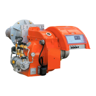
ITALIANO DESCRIZIONE COMPONENTI 1 Testa di combustione 2 Guarnizione 3 Flangia attacco bruciatore 4 Valvola farfalla gas 5 Servomotore regolazione gas / gasolio 6 Display apparecchiatura 7 Pressostato aria 8 Servomotore regolazione aria 9 Quadro elettrico 10 Cerniera 11 Motore ventola 12 Convogliatore aria in aspirazione 13 Regolatore di portata gasolio 14 Elettrovalvola gasolio ritorno... -
Page 11: Dimensioni Di Ingombro
ITALIANO DIMENSIONI DI INGOMBRO Modello TBML 350 ME 1616 599.5 Modello E Ø F Ø LØ TBML 350 ME Modello N Ø TBML 350 ME 9 / 42 0006160077_201401... -
Page 12: Applicazione Del Bruciatore Alla Caldaia
ITALIANO APPLICAZIONE DEL BRUCIATO- RE ALLA CALDAIA MONTAGGIO GRUPPO TESTATA Accertarsi che la testa di combustione penetri nel focolare nella misura richiesta dal costruttore della caldaia. Prima di installare il bruciatore alla caldaia, accertarsi che l'ugello sia adeguato alla potenza richiesta. Per movimentare il bruciatore si consiglia di agganciare ai golfari una adeguata attrezzatura di sollevamento. -
Page 13: Montaggio Gruppo Cerniera A Destra O Sinistra
ITALIANO MONTAGGIO GRUPPO CERNIERA A DESTRA O SINISTRA Il bruciatore è dotato di cerniera ambidestra, quindi è possibile invertire il lato di apertura del corpo ventilante. Il bruciatore viene fornito di serie con cerniera montata sul lato sinistro. Per consentire l’apertura massima e facilitare quindi le operazio- ni di manutenzione, si consiglia di disporre la cerniera sul lato opposto del bruciatore rispetto alla posizione in cui è... -
Page 14: Impianto Di Alimentazione Con Combustibile Liquido
ITALIANO IMPIANTO DI ALIMENTAZIONE CON COMBUSTIBILE LIQUIDO La pompa del bruciatore deve ricevere il combustibile da un adat- to circuito di alimentazione con pompa ausiliaria, eventualmente provvisto di regolatore di pressione regolabile da 0,5 a 3 bar. Il valore della pressione di alimentazione del combustibile alla pompa del bruciatore non deve variare sia con bruciatore fermo che con bruciatore funzionante alla massima erogazione di com- bustibile richiesta dalla caldaia. -
Page 15: Descrizione Del Funzionamento
ITALIANO DESCRIZIONE DEL FUNZIONA- MENTO Il bruciatore è a funzionamento completamente automatico; chiu- dendo l’interruttore generale e quello del quadro di comando il bruciatore viene inserito. Il funzionamento del bruciatore viene gestito dai dispositivi di co- mando e controllo. La posizione di “blocco” è una posizione di sicurezza in cui il bru- ciatore si porta automaticamente, quando qualche particolare del bruciatore o dell’impianto è... -
Page 16: Descrizione Del Funzionamento
ITALIANO DESCRIZIONE DEL FUNZIONA- MENTO Il bruciatore è a funzionamento completamente automatico; chiu- dendo l’interruttore generale e quello del quadro di comando il bruciatore viene inserito. Il funzionamento del bruciatore viene gestito dai dispositivi di co- mando e controllo. La posizione di “blocco” è una posizione di sicurezza in cui il bru- ciatore si porta automaticamente, quando qualche particolare del bruciatore o dell’impianto è... -
Page 17: Accensione E Regolazione Combustibile Liquido
ITALIANO • Verificare l'intervento del rilevatore di fiamma. ACCENSIONE E REGOLAZIONE COMBUSTIBILE LIQUIDO Si consiglia di effettuare prima l’accensione con il combustibile liquido in quanto l’erogazione è condizionata dall’ugello. Successivamente per la regolazione a gas agire sullo stabilizzato- re di pressione della rampa gas. •... - Page 18 ITALIANO SCHEMA COLLEGAMENTO POMPA HP MODELLO VBH • Quando il bruciatore è in funzione al “minimo”, regolare l’aria ed il gasolio nelle quantità necessarie per assicurare una buona combustione. Per il funzionamento a gasolio impiegare ugelli modello BER- GONZO tipo B5 45° senza spillo a seconda della portata termica massima regolata.
-
Page 19: Ugello Bergonzo Senza Spillo
ITALIANO UGELLO BERGONZO SENZA SPILLO Per il funzionamento a gasolio impiegare ugelli modello BER- GONZO tipo B5 45° senza spillo a seconda della portata termica massima regolata. Nei grafici seguenti sono rappresentate le curve che riportano i valori della portata di combustibile erogata dagli ugelli in funzione della pressione di ritorno. - Page 20 ITALIANO 18 / 42 0006160077_201401...
- Page 21 ITALIANO 19 / 42 0006160077_201401...
- Page 22 ITALIANO 20 / 42 0006160077_201401...
- Page 23 ITALIANO 21 / 42 0006160077_201401...
- Page 24 ITALIANO 22 / 42 0006160077_201401...
- Page 25 ITALIANO 23 / 42 0006160077_201401...
- Page 26 ITALIANO 24 / 42 0006160077_201401...
-
Page 27: Accensione E Regolazione Gas Metano
ITALIANO nella sua sede. La cellula non “vede” la luce del giorno o di una ACCENSIONE E REGOLAZIONE comune lampada. L’eventuale verifica di sensibilità può essere GAS METANO fatta con la fiamma di un accendino o di una candela. Per as- sicurare un corretto funzionamento il valore di tensione della •... -
Page 28: Descrizione Del Funzionamento Pressostato Aria
ITALIANO • Dopo aver regolato l’aria per il minimo, salire di potenza e pro- cedere alla definizione della curva di lavoro come indicato nel manuale dell'apparecchiatura. • Effettuare il controllo della combustione con l'apposito strumen- to in tutti i punti intermedi della curva di modulazione. •... - Page 29 ITALIANO DESCRIZIONE DEL FUNZIONAMENTO PRESSOSTATO Con bruciatore alla massima potenza regolare il pressostato di massima diminuendo il valore di taratura fino a che il contatto NC I pressostati di controllo della pressione del gas (minima e mas- (normalmente chiuso), si apre. Leggere il valore sulla ghiera di sima) hanno lo scopo di impedire il funzionamento del bruciatore regolazione e regolare la stessa aumentata di 5 mbar.
- Page 30 ITALIANO POTENZA ALL'ACCENSIONE La norma EN 676 prescrive che per i bruciatori con potenza mas- sima oltre i 120 kW l'accensione deve avvenire ad una potenza Pstart ridotta rispetto alla potenza massima di funzionamento Pmax a cui è tarato il bruciatore. Pstart dipende dal tempo di sicurezza dell’apparecchiatura del bruciatore;...
-
Page 31: Precisazioni Sull'uso Del Propano
ITALIANO PRECISAZIONI SULL'USO DEL PROPANO Serbatoio 2,5 Kg/h 4,5 Kg/h 6,5 Kg/h 9 Kg/h 12 Kg/h • Valutazione, indicativa, del costo di esercizio; 3000 l. - 1 m3 di gas liquido in fase gassosa ha un potere calorifico 11,5 Serbatoio 4 Kg/h 6,5 Kg/h 16 Kg/h... -
Page 32: Schema Di Principio Per Riduzione Pressione G.p.l. A Due Stadi Per Bruciatore Oppure Caldaia
ITALIANO SCHEMA DI PRINCIPIO PER RIDUZIONE PRESSIONE G.P.L. A DUE STADI PER BRUCIATORE OPPURE CALDAIA Manometro e presa di pressione Riduttore di 1° salto Riduttore di 2° salto Uscita ~ 30 mbar Uscita ~ 30 mbar Portata ~ il doppio del massimo richiesto Portata ~ il doppio del massimo richiesto dall’utilizzatore dall’utilizzatore... -
Page 33: Manutenzione
ITALIANO MANUTENZIONE Effettuare almeno una volta all’anno e comunque in conformità alle norme vigenti, l’analisi dei gas di scarico della combustione verificando la correttezza dei valori di emissioni. Al termine della stagione di riscaldamento, eseguire le seguenti operazioni: • Pulire le serrande aria, il pressostato aria con presa di pressio- ne ed il relativo tubo. -
Page 34: Tabella Portata Ugelli
ITALIANO TABELLA PORTATA UGELLI Ugello Pressione pompa Ugello G.P.H. Portata all'uscita dell'ugello G.P.H. 0,40 1,27 1,36 1,44 1,52 1,59 1,67 1,73 1,80 1,86 1,92 1,98 2,04 2,10 2,15 0,40 0,50 1,59 1,70 1,80 1,90 1,99 2,08 2,17 2,25 2,33 2,40 2,48 2,55 2,62... -
Page 35: Istruzioni Per L'accertamento Delle Cause Di Irregolarità Nel Funzionamento E La Loro Eliminazione
ITALIANO ISTRUZIONI PER L'ACCERTAMENTO DELLE CAUSE DI IRREGOLARITÀ NEL FUNZIONAMENTO E LA LORO ELIMINAZIONE IRREGOLARITÁ POSSIBILE CAUSA RIMEDIO Termostati (caldaia o ambiente) o Alzare il valore dei termostati oppure pressostati, aperti. attendere che si chiudano i contatti per Fotoresistenza in corto circuito. diminuzione naturale della temperatura Bruciatore che non si av- Mancanza di tensione in linea, inter-... - Page 36 ITALIANO IRREGOLARITÁ POSSIBILE CAUSA RIMEDIO Temperatura di esercizio della caldaia troppo bassa (inferiore al Aumentare la temperatura di esercizio. punto di rugiada). Corrosioni interne nella caldaia. Aumentare la portata di gasolio se la Temperatura dei fumi troppo bassa, caldaia lo consente. indicativamente al di sotto dei 130°...
- Page 37 ITALIANO IRREGOLARITÁ POSSIBILE CAUSA RIMEDIO Regolare. La pressione della pompa non è Scaricare l'acqua dalla cisterna regolare. servendosi di una pompa adatta. Non L’apparecchio va in blocco spruz- Presenza di acqua nel combustibi- usare mai per questo lavoro la pompa zando combustibile liquido senza il del bruciatore.
-
Page 38: Schemi Elettrici
ITALIANO SCHEMI ELETTRICI 36 / 42 0006160077_201401... - Page 39 ITALIANO 37 / 42 0006160077_201401...
- Page 40 ITALIANO 38 / 42 0006160077_201401...
- Page 41 ITALIANO 39 / 42 0006160077_201401...
- Page 42 ITALIANO 40 / 42 0006160077_201401...
- Page 43 ITALIANO ELETTROVALVOLA PRINCIPALE RITORNO APPARECCHIATURA APPARECCHIATURA PER DUE COMBUSTIBILI ELETTROVALVOLA PRINCIPALE MANDATA FOTORESISTENZA / ELETTRODO DI IONIZZAZIONE / ELETTROVALVOLA DI SICUREZZA FOTOCELLULA UV ELETTROVALVOLA DI SICUREZZA MANDATA RELE’ TERMICO ELETTROVALVOLA DI SICUREZZA RITORNO RELE’ TERMICO POMPA GNYE VERDE / GIALLO FU1÷4 FUSIBILI SPIA BLOCCO ESTERNA / LAMPADA FUNZIONAMEN- BRUNO...
- Page 44 ITALIANO 42 / 42 0006160077_201401...
- Page 45 ENGLISH INDEX ENGLISH Instructions for use in safe conditions ..............................pag 3 Technical specifications ..................................pag 6 Design characteristics ................................pag 7 Technical functional characteristics ............................pag 7 Operating range ..................................pag 7 Component description ................................pag 8 Overall dimensions ..................................pag 9 Burner connection to the boiler ...............................pag 10 HINGE UNIT ASSEMBLY TO THE RIGHT OR LEFT ......................
- Page 46 ENGLISH DECLARATION OF CONFORMITY CE0085: DVGW CERT GmbH, Josef-Wirmer Strasse 1-3-53123 Bonn (D) We hereby declare under our own responsibility, that our domestic and industrial blown air burners fired by gas, oil and dual fuel, series: BPM...; BGN…; BT…; BTG…; BTL…; TBML...; Comist…; GI…; GI…Mist; Minicomist…; PYR…; RiNOx…; Spark...; Sparkgas...; TBG...;TBL...;...
- Page 47 Contact only qualified personnel. product and must be given to the user. • Any product repairs must only be carried out by BALTUR autho- • The user must keep the booklet with care for any future con- rised assistance centres or its local retailer using only original sultation.
- Page 48 ENGLISH SAFETY INSTRUCTIONS FOR INSTALLATION INSTRUCTIONS FOR START-UP, INSPECTION, USE AND MAINTENANCE • The equipment must be installed in a suitable area with ade- quate ventilation according to the standards and regulations in • Start-up, inspection and maintenance of the equipment must force.
- Page 49 ENGLISH • If the burner repeatedly shuts down in lock-out, do not keep • If the user is away for some time, close the main gas feed valve trying to manually reset it but call a qualified technician to solve to the burner.
- Page 50 The measurement has been carried out in Baltur's laboratory, in accordance with EN 150361 standard. ** Sound pressure: mean value referred to the measurement surface Acoustic pressure was obtained characterizing Baltur's laboratory with a sample source, this measurement has an accuracy of class 2 (engineering class) with a standard deviation f 1.5 dB(A).
- Page 51 ENGLISH DESIGN CHARACTERISTICS TECHNICAL FUNCTIONAL CHARACTERISTICS The burner consists of: • Dual burner, able to operate alternately with natural gas or with • Ventilating part in light aluminium alloy. diesel (max viscosity 1.5° E at 20°C). • Centrifugal fan for high performances. •...
- Page 52 ENGLISH COMPONENT DESCRIPTION 1 Combustion head 2 Seal 3 Burner connection flange 4 Gas throttle valve 5 Gas / diesel regulator servomotor 6 Equipment display 7 Air pressure switch 8 Air regulation servomotor 9 Electrical panel 10 Hinge 11 Fan motor 12 Intake air conveyor 13 Diesel flow rate regulator 14 Diesel return solenoid valve...
- Page 53 ENGLISH OVERALL DIMENSIONS Model TBML 350 ME 1616 599.5 Model E Ø F Ø LØ TBML 350 ME Model N Ø TBML 350 ME 9 / 9 0006160077_201401...
- Page 54 ENGLISH BURNER CONNECTION TO THE BOILER ASSEMBLING THE HEAD UNIT Check that combustion head penetrates the combustion chamber by the measure requested by the manufacturer of the boiler. Before installing the burner to the boiler, make sure that the nozzle is adjusted to the power required.
- Page 55 ENGLISH HINGE UNIT ASSEMBLY TO THE RIGHT OR LEFT The burner hinge can be opened both ways, it is therefore possi- ble to reverse the opening side of the ventilating body. As a standard, the burner is supplied with the hinge installed on the left side.
- Page 56 ENGLISH LIQUID FUEL SUPPLY SYSTEM The burner pump must receive the fuel from a suitable supply circuit featuring an auxiliary pump which may feature a pressure regulator adjustable from 0.5 to 3 bar. The fuel supply pressure to the burner pump must not change both with burner off and with working burner at the maximum fuel output required by the boiler.
- Page 57 ENGLISH OPERATING DESCRIPTION Burner operation is fully automatic; it starts up by enabling the main switch and the control panel switch. Burner operation is managed by command and control devices. The “lock-out” position is a safety position that the burner auto- matically assumes when a burner or system component is not working properly.
- Page 58 ENGLISH OPERATING DESCRIPTION Burner operation is fully automatic; it starts up by enabling the main switch and the control panel switch. Burner operation is managed by command and control devices. The “lock-out” position is a safety position that the burner auto- matically assumes when a burner or system component is not working properly.
- Page 59 ENGLISH IGNITION AND ADJUSTMENT WITH LIQUID FUEL It is recommended to first make the ignition with the liquid fuel as the delivery is conditioned by the nozzle. Then to regulate the gas operate the pressure regulator on the gas train. •...
- Page 60 ENGLISH PUMP CONNECTION DIAGRAM HP MODEL VBH • When the burner is working at its "minimum" output, adjust the air and diesel in the proper quantities to ensure a good com- bustion. For diesel operation, use nozzles model BERGONZO type B5 45° without pin depending in the maximum regulated heat output.
- Page 61 ENGLISH BERGONZO NOZZLE WITHOUT PIN For diesel operation, use nozzles model BERGONZO type B5 45° without pin depending in the maximum regulated heat output. The diagrams below represent the curves showing the values of the fuel flow rate delivered by the nozzles depending on the return pressure.
- Page 62 ENGLISH 18 / 18 0006160077_201401...
- Page 63 ENGLISH 19 / 19 0006160077_201401...
- Page 64 ENGLISH 20 / 20 0006160077_201401...
- Page 65 ENGLISH 21 / 21 0006160077_201401...
- Page 66 ENGLISH 22 / 22 0006160077_201401...
- Page 67 ENGLISH 23 / 23 0006160077_201401...
- Page 68 ENGLISH 24 / 24 0006160077_201401...
- Page 69 ENGLISH NATURAL GAS IGNITION AND RE- terminals of the panel shown in the wiring diagram. • When the burner is working at its "minimum" output, adjust the GULATION air and diesel in the proper quantities to ensure a good com- bustion.
- Page 70 ENGLISH • After adjusting the air for the operation at the "minimum" output, increase the power and proceed to define the operating curve as described in the equipment manual. • Check the combustion using the specific instrument at all inter- mediate points on the modulation curve.
- Page 71 ENGLISH GAS PRESSURE SWITCH OPERATION DESCRIPTION re switch for maximum pressure, diminishing the regulation value The gas pressure switches (minimum and maximum) prevent until the NC (normally closed) contact opens. Read the value on the burner from operating when gas pressure is not between the the regulation ferrule and set it to a value increased by 5 mbar.
- Page 72 ENGLISH POWER AT START-UP The standard EN 676 prescribes that for burners with maximum output above 120 kW the ignition must occur at a lower power |b|Pstart|bb| than the maximum power of operation |b|Pmax|bb| at which the burner is calibrated. |b|Pstart|bb| it depends on the safety time of the burner equip- ment;...
- Page 73 ENGLISH SPECIFICATIONS FOR PROPANE USE 11.5 4 Kg/h 6.5 Kg/h 16 Kg/h 21 Kg/h 5000 l tank • Operating costs approximate assessment; Kg/h - 1 m3 of liquid gas in gaseous stage has a lower heating capacity, of nearly 25.6 kWh. - To obtain 1 cu.m of gas, about 2 kg of liquid gas are needed, i.e.
- Page 74 ENGLISH DIAGRAM ILLUSTRATING THE PRINCIPLE OF L.P.G. PRESSURE REDUCTION IN TWO STAGES FOR BURNER OR BOILER Pressure gauge and pressure intake 1st step reducer 2nd step reducer Output ~ 30 mbar Output ~ 30 mbar Flow rate ~ double the maximum required Flow rate ~ double the maximum required by the user by the user...
- Page 75 ENGLISH MAINTENANCE Analyse combustion gases and check that the emission values are correct at least once a year, in compliance with current law. Carry out the following operations at the end of the heating sea- son: • Clean air shutters, the air pressure switch with pressure port and the relevant pipe.
- Page 76 ENGLISH NOZZLE FLOW RATE TABLE Nozzle Pump Nozzle output output flow-rate flow-rate G.P.H. Nozzle output flow-rate G.P.H. 0,40 1,27 1,36 1,44 1,52 1,59 1,67 1,73 1,80 1,86 1,92 1,98 2,04 2,10 2,15 0,40 0,50 1,59 1,70 1,80 1,90 1,99 2,08 2,17 2,25 2,33...
- Page 77 ENGLISH TROUBLESHOOTING INSTRUCTIONS ANOMALY POSSIBLE CAUSE REMEDY Raise the thermostats settings, or Thermostats (boiler or room) or wait that the contacts close for natural pressure switches are open. decrease of temperature or pressure. Photoresistant-cell in short circuit. The burner does not start Replace it.
- Page 78 ENGLISH ANOMALY POSSIBLE CAUSE REMEDY Boiler operating temperature too low (below the dew point). Increase the operating temperature. Corrosion inside the boiler. Smoke temperature too low, Increase diesel flow rate is the boiler approximately below 130 °C for allows it. diesel.
- Page 79 ENGLISH ANOMALY POSSIBLE CAUSE REMEDY Adjust. Pump pressure is not regular. Drain water from the tank using a Water in the fuel. suitable pump. Never use the burner The burner goes to shut down Too much combustion air. pump for this purpose. spraying liquid fuel but without fla- Air passage between deflector disk Reduce combustion air.
- Page 80 ENGLISH WIRING DIAGRAMS 36 / 36 0006160077_201401...
- Page 81 ENGLISH 37 / 37 0006160077_201401...
- Page 82 ENGLISH 38 / 38 0006160077_201401...
- Page 83 ENGLISH 39 / 39 0006160077_201401...
- Page 84 ENGLISH 40 / 40 0006160077_201401...
- Page 85 ENGLISH MAIN RETURN SOLENOID VALVE EQUIPMENT DUAL FUEL EQUIPMENT MAIN DELIVERY SOLENOID VALVE PHOTORESISTOR / IONISATION ELECTRODE / UV SAFETY SOLENOID VALVE PHOTOCELL DELIVERY SAFETY SOLENOID VALVE THERMAL RELAY RETURN SAFETY SOLENOID VALVE PUMP THERMAL RELAY GNYE GREEN / YELLOW FU1÷4 FUSES BLUE EXTERNAL LOCK INDICATOR LIGHT/ AUXILIARY...
- Page 86 ENGLISH 42 / 42 0006160077_201401...
- Page 88 BALTUR S.P.A. Via Ferrarese, 10 44042 Cento (Fe) - Italy Tel. +39 051-6843711 Fax. +39 051-6857527/28 www.baltur.it info@baltur.it Il presente catalogo riveste carattere puramente indicativo. La casa, pertanto, si riserva ogni possibilità di modifica dei dati tecnici e di quant'altro in esso riportato.
Need help?
Do you have a question about the TBML 350 ME and is the answer not in the manual?
Questions and answers