
Related Manuals for Quick BTR185 Series


Summary of Contents for Quick BTR185 Series
- Page 1 BTR185 REV 009A ELICA DI MANOVRA RETRATTILE MANUALE D'INSTALLAZIONE E USO pag. 3 RETRACTABLE THRUSTER INSTALLATION AND USE MANUAL page 25...
- Page 3 2 - Fornitura e dotazioni Pag. 5 2.0 - Fornitura di serie e materiale incluso nella confezione Pag. 5 2.1 - Attrezzi necessari per l'installazione Pag. 5 2.2 - Accessori Quick consigliati Pag. 5 ® 3 - Sicurezza Pag. 5 3.0 - Avvertenze...
-
Page 4: Informazioni Sul Prodotto
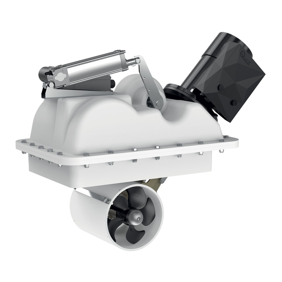
è stata progettata e realizzata per effettuare un’apertura del portello priva di interferenze (se installata come indicazioni). Motore elettrico, riduttore, leveraggi e tutti gli altri componenti sono forniti da Quick già assemblati sulla struttura ®... - Page 5 • Tronchesi • Trapano con punta da Ø 8,5 mm • Chiave esagonale da 2,5 mm • Chiave a forchetta da 8 mm e 13 mm 2.2 - Accessori Quick consigliati ® per l'azionamento dell'elica di manovra PANNELLI DI COMANDO •...
-
Page 6: Installazione
4 - Installazione BTR185 4.0 - Posizionamento dell'elica di manovra minimo 0,75 volte il Ø del tunnel • Per evitare fenomeni di cavitazione nell’elica, si dovrà posizionare il tunnel più a fondo possibile. • Per evitare danneggiamenti, posizionare l'elica retrattile in modo che il portello non sia influenzato dal cono di propulsione dell’elica dell'imbarcazione (esempi 1 e 2), in entrambi i sensi di marcia. - Page 7 4 - Installazione BTR185 4.1 - Installazione della controflangia Accedere direttamente nella parte interna dello scafo, nella zona in cui l'elica retrattile verrà installata. La posizione dell'elica retrattile dovrà permettere agevoli manovre di installazione. Fig. 1A CARTA GOMMATA CONTROFLANGIA • Proteggere la sede della guarnizione con carta gommata per evitare di sporcarla, fino all’installazione dell'elica retrattile (Fig.
- Page 8 4 - Installazione BTR185 4.1 - Installazione della controflangia Fig. 1C CONTROFLANGIA CUT LINE CONTROFLANGIA PRUA SCAFO CUT LINE CONTROFLANGIA SCAFO • Sagomare le parti centrali dei 4 lati della controflangia (Y) adattandoli alla curva dello scafo (fig. 1C). • Appoggiare la controflangia opportunamente tagliata e ve- PRUA rificare che i quattro lati aderiscano allo scafo, se così...
- Page 9 4 - Installazione BTR185 Fig. 4 • Realizzare l’apertura dello scafo tagliando lungo la linea dell’area di taglio tracciata (fig. 4). GRP LAYERS Fig. 5 Sistema di laminazione consigliato da Quick ® CONTROFLANGIA GRP LAYERS COLLA STRUTTURALE GRP LAYERS GRP LAYERS SCAFO •...
- Page 10 4 - Installazione BTR185 4.2 - Realizzazione e installazione del portello di chiusura ATTENZIONE: prestare particolare attenzione ad evitare interferenze tra il coperchio e l’apertura dello scafo. Contatti troppo precisi provocheranno danni all’intero sistema di movimento (fig.7). Fig. 7 Fig. 8 LATO CERNIERA CONTROFLANGIA...
- Page 11 4 - Installazione BTR185 Fig. 12 Min. 5 mm ANGOLARE CONTROFLANGIA Min. 80 mm CERNIERA SCAFO PORTELLO SCAFO 15 mm ATTENZIONE: per permettere un solido fissaggio della cerniera e della staffa, il portello non deve presentare al suo interno zone Fig.
- Page 12 4 - Installazione BTR185 4.4 - Verifica e regolazione meccanica del sistema Attenersi alla sequenza riportata di seguito per effettuare la verifica dell’apertura fig. 15 del portello: Fig. 15 • L'elica retrattile non deve essere alimentata. • Sfilare l’anello e rimuovere il perno (part. A). •...
- Page 13 4 - Installazione BTR185 4.6 - Procedura di regolazione ATTENZIONE: la seguente procedura deve essere eseguita da personale qualificato. ATTENZIONE: presenza di parti meccaniche in movimento. Porre particolare attenzione quando si opera sull'elica retrattile se è alimentata. • Assicurarsi che tutti i collegamenti elettrici siano stati compiuti in maniera corretta. fig.
- Page 14 4 - Installazione BTR185 4.7 - Regolazione attuatore Apertura dello sportello laterale dell’attuatore. fig. 20 Interno dell’attuatore SUPPORTO DI PLASTICA SUPPORTO DI PLASTICA CAM 2 CAM 1 SWITCH FC2 SWITCH FC1 VITE DI FISSAGGIO REGOLAZIONE DI MASSIMA CAMMA REGOLAZIONE DI MASSIMA CHIUSURA DELL'ELICA APERTURA DELL'ELICA •...
-
Page 15: Schema Di Collegamento
5 - Schema di collegamento BTR185 5.0 - Sistema base BTR185 Esempio di collegamento TCD 1042 TCD 1022 ROSSO NERO ROSSO PROTEZIONE TERMICA NERO STACCABATTERIA INTERRUTTORE MOTORE FUSIBILE VEDI TABELLA A PAG.4 PROLUNGHE (OPZIONALI) SCHEDA FUSIBILE ELETTRONICA RAPIDO 4A RTC R1 BATTERIA 12/24V SDOPPIATORE... - Page 16 5 - Schema di collegamento BTR185 5.1 - Scheda RTC R1 PULSANTI MOVIMENTO MANUALE SELETTORE ROTATIVO CORRENTE ATTUATORE DIP-SWITCH SELEZIONE OPZIONI LED VERDE ALIMENTAZIONE COLLEGAMENTO CAN BUS LED BICOLORE STATO ATTUATORE LED ROSSO SEGNALAZIONE PROBLEMI FUSIBILE ATTUATORE NEGATIVO GRUPPO TELEINVERTITORE AL TELERUTTORE SX ROSSO NERO...
-
Page 17: Funzionamento
6 - Funzionamento BTR185 6.0 - Dip-Switch selezione opzioni SELEZIONE FUNZIONE DIP-SWITCH Riservata (mantenere sempre off) 2 3 4 Indica alla stazione di comando CAN che il propulsore è di prua (OFF) Indica alla stazione di comando CAN che il propulsore è di poppa (ON) Riservata (mantenere sempre off) Riservata (mantenere sempre off) 1 2 3... - Page 18 7 - Segnalazioni BTR185 7.0 - Segnalazioni luminose Di seguito si riporta il significato delle segnalazioni luminose fornite dalla scheda RTC R1 (vedi scheda elettronica a pag.13). LED POWER (VERDE) STATO LED DESCRIZIONE SPENTO Scheda non alimentata LAMPEGGIO BREVE Scheda alimentata ma comando non abilitato LAMPEGGIO VELOCE Scheda alimentata e modalità...
-
Page 19: Avvertenze Importanti
E’ provvisto di protezioni che ne limitano il funzionamento fino ad un tempo massimo, come riportato sul manuale dei comandi. E’ assolutamente vietato bypassare o modificare tali protezioni per aumentare il tempo di funzionamen- to, pena la decadenza della garanzia e di qualsiasi responsabilità da parte di Quick SPA. -
Page 20: Manutenzione
ETICHETTA Manutenzione BTR185 I Thruster Quick sono costituiti da materiale resistenti all’ambiente marino: è indispensabile, in ogni caso, rimuovere perio- ® dicamente i depositi di sale che si formano sulle superfici esterne per evitare corrosioni e di conseguenza inefficienza del sistema. - Page 21 Manutenzione BTR185 BTR 1806512 BTR 1806524 BTR 1808512 BTR 1808524 BTR 1810512 BTR 1810524 86 85 MANUALE D’INSTALLAZIONE E USO BTR185 - REV009A...
- Page 22 Ricambi BTR185 N° DESCRIZIONE CODICE OSP KIT CARTER ‘A’ PER ELICA FVSGCARTABTQA00 OSP MOTORE ELICHE 3300W12V BTR185+T FVEMFEL3312B18T OSP KIT CARTER ‘B’ PER ELICA FVSGCARTABTQB00 OSP MOTORE ELICHE 3300W24V BTR185+T FVEMFEL3324B18T OSP KIT ANODI ELICA BTR185 FVSGANBTR185A00 OSP MOTORE ELICHE 4300W12V BTR185+T FVEMFEL4312B18T OSP KIT RIDUTTORE BTQ185 DP FVSGGBBT185DA00 OSP MOTORE ELICHE 4300W24V BTR185+T FVEMFEL4324B18T...
- Page 23 Dimensioni elica di manovra retrattile BTR185 599 (23 MOD. BTR1806512 BTR1806524 BTR1808512 BTR1808524 BTR1810512 BTR1810524 A - mm (inch) 713 (28” 1/16) 743 (29” 1/4) 801 (31” 17/32) B - mm (inch) 292 (11” 1/2) 323 (12” 23/32) 384 (15” 1/8) MANUALE D’INSTALLAZIONE E USO BTR185 - REV009A...
- Page 25 Pag. 26 2 - Supplied parts Pag. 27 2.0 - Package contains the following parts Pag. 27 2.1 - Tools needed for installation Pag. 27 2.2 - Quick ”accessories recommended Pag. 27 ® 3 - Safety Pag. 27 3.0 - Warnings Pag.
-
Page 26: Information About The Product
(if properly installed, as per instructions provided). Electric motor, gear, levers and all other components are supplied by Quick , already assembled on the supporting ®... -
Page 27: Supplied Parts
• THF6 fuseholders TFH3 - TFH6 FUSEHOLDERS 3 - Safety BTR185 3.0 - Warnings • The thruster Quick have been designed and manufactured for nautical use. ® • Do not use these appliances for other uses. • Quick shall accept no responsibility for direct or indirect damages caused by improper use of the appliance or an ®... -
Page 28: Installation
4 - Installation BTR185 4.0 - Thruster positioning minimum 0,75 times Ø tunnel • To avoid cavitation in the propeller, the tunnel must be positioned as low as possible. • In order to prevent any damage, position the retractable thruster in such a way that the closing lid is not affected by the propulsion cone of the boat propeller (example 1 and 2), in both directions. - Page 29 4 - Installation BTR185 4.1 - Counter flange’s installation Directly access inside the hull, where the thruster will be installed. The thruster position must enable easy maintenance operations. Fig. 1A GUMMED PAPER COUNTER FLANGE • Protect the gasket with gummed paper tape up to the installation of the propeller to prevent it from getting dirty (Fig. 1A). Fig.
- Page 30 4 - Installation BTR185 4.1 - Counter flange’s installation Fig. 1C COUNTER FLANGE CUT LINE COUNTER FLANGE HULL CUT LINE COUNTER FLANGE HULL • Shape the central section of the 4 sides of counter flange Y in order to adjust them to the hull curve (Fig. 1C). •...
- Page 31 4 - Installation BTR185 Fig. 4 • Cut the hull along the cutting area previously marked (fig. 4). GRP LAYERS Fig. 5 Laminating system recommended by Quick ® COUNTER FLANGE GRP LAYERS STRUCTURAL ADHESIVE GRP LAYERS GRP LAYERS HULL • Align the counter flange to the hull’s opening and check that the two heights (X) are correct. Resinate the counter flange, or solder it in case of aluminium or steel, according to the techniques the most suitable to the hull’s material (fig.
- Page 32 4 - Installation BTR185 4.2 - Closing lid’s preparation and installation WARNING: pay particular attention to avoid interferences between the lid and the hull opening. Too precise contacts will cause damages to the entire moving system (fig.7). Fig. 7 Fig. 8 HINGE SIDE COUNTER FLANGE...
- Page 33 4 - Installation BTR185 Fig. 12 Min. 5 mm ANGLE BAR COUNTER FLANGE Min. 80 mm HINGE HULL HULL 15 mm WARNING: in order to allow a stable fixing of hinge and bracket, the lid must present neither empty areas nor non-structural fillings Fig.
- Page 34 4 - Installation BTR185 4.4 - Mechanical system check and adjustmen Follow the sequence described below to verify the opening of the hatch: fig. 15 Fig. 15 • The BTR propeller should be disconnected from power. • Take the ring off and remove the pin (part. A). •...
-
Page 35: Adjustment Procedure
4 - Installation BTR185 4.6 - Adjustment procedure WARNING: the following procedure must be carried out by qualified personnel. WARNING: presence of moving mechanical parts. Pay extreme attention when operating on the BTR propeller if con- nected to power. • Ensure that all electrical connections have been properly carried out. fig. - Page 36 4 - Installation BTR185 4.7 - Actuator’s adjustment Opening of the actuator’s side lid fig. 20 Actuator’s interior PLASTIC SUPPORT PLASTIC SUPPORT CAM 2 CAM 1 SWITCH FC2 SWITCH FC1 FIXING SCREW ADJUSTMENT OF THE THRUSTER’S ADJUSTMENT OF THE THRUSTER’S MAXIMUM CLOSING MAXIMUM CLOSING •...
-
Page 37: Connection Diagram
(OPTIONAL) TO THE SERVICES BATTERY FUSE 10A SWITCH QUICK ACTING F TO THE SERVICES BATTERY ACTUATOR COMMON NEGATIVE FOR THE BATTERY GROUPS. WARNING: IN CASE OF OVERTEMPERATURE, THE THERMAL PROTECTION ON THE MOTOR WILL OPEN AND INTERRUPT THE NEGATIVE CONTACT ON THE SOLENOID UNIT. WAIT AS LONG AS THE SYSTEM NEEDS TO REACTIVATE. - Page 38 5 - Connection diagram BTR185 5.1 - RTC R1 BOARD MANUAL OPERATION BUTTONS ROTARY SWITCH ACTUATOR CURRENT LIMIT DIP-SWITCH OPTIONS SELECTION GREEN LED POWER CAN BUS LINK BI-COLOUR LED LINEAR ACTUATOR STATUS RED LED ERRORS FUSE ACTUATOR NEGATIVE GROUP REVERSING CONTACTOR TO LEFT CONTACTOR BLACK...
-
Page 39: Operation
6 - Operation BTR185 6.0 - Option selection Dip-Switch SELECTION FUNCTION DIP-SWITCH Reserved (always keep off) 2 3 4 Informs the CAN control station that the thruster is in the bow (OFF) Informs the CAN control station that the thruster is in the stern (ON) Reserved (always keep off) Reserved (always keep off) 1 2 3... - Page 40 7 - Notification BTR185 7.0 - Notification signs Legend of error notifications concerning the RTC R1 board (see the board on page 38) LED POWER (GREEN) LED STATUS DESCRIPTION Board not powered SLOW FLASHING Powered board but disabled control FAST FLASHING Powered board and actuator’s manual movement mode on ON WITH SHORT SWITCHING OFF Powered board but disabled control and active link with the CAN control station...
- Page 41 It is equipped with protections which limit its operation at a maximum time span, as reported on the controls’ man- ual. It is strongly forbidden to bypass or modify such protections in order to increase the operating time span, lest voiding the warranty and thus lifting any responsibility from Quick SPA.
-
Page 42: Maintenance
Maintenance BTR185 Quick Thrusters are made in materials that are resistant to the sea environment: In any case, it is indispensable to periodi- ® cally remove salt deposits that form on the outer surfaces to avoid corrosions and consequent system inefficiency. - Page 43 Maintenance BTR185 BTR 1806512 BTR 1806524 BTR 1808512 BTR 1808524 BTR 1810512 BTR 1810524 86 85 BTR185 INSTALLATION AND USE MANUAL - REV009A...
-
Page 44: Spare Parts
Spare parts BTR185 DESCRIPTION CODE OSP KIT CARTER ‘A’ FOR PROPELLER FVSGCARTABTQA00 OSP PROPELLER MOTOR 3300W12V BTR185+T FVEMFEL3312B18T OSP KIT CARTER ‘B’ FOR PROPELLER FVSGCARTABTQB00 OSP PROPELLER MOTOR 3300W24V BTR185+T FVEMFEL3324B18T OSP KIT ANODS FOR PROPELLER BTR185 FVSGANBTR185A00 OSP PROPELLER MOTOR 4300W12V BTR185+T FVEMFEL4312B18T OSP KIT GEARLEG BTQ185 DP FVSGGBBT185DA00... - Page 45 Retractable thruster dimensions BTR185 599 (23 MOD. BTR1806512 BTR1806524 BTR1808512 BTR1808524 BTR1810512 BTR1810524 A - mm (inch) 713 (28” 1/16) 743 (29” 1/4) 801 (31” 17/32) B - mm (inch) 292 (11” 1/2) 323 (12” 23/32) 384 (15” 1/8) BTR185 INSTALLATION AND USE MANUAL - REV009A...
- Page 46 NOTES...
- Page 48 MANUALE D'INSTALLAZIONE ED USO INSTALLATION AND USE MANUAL RETRACTABLE THRUSTER Codice di serie del prodotto / Product code and serial number QUICK S.p.A. - Via Piangipane, 120/A - 48124 Piangipane (RAVENNA) - ITALY ® Tel. +39.0544.415061 - Fax +39.0544.415047 - www.quickitaly.com - quick@quickitaly.com...
Need help?
Do you have a question about the BTR185 Series and is the answer not in the manual?
Questions and answers