Table of Contents
Advertisement
Quick Links
Advertisement
Table of Contents

Related Manuals for Datavideo HS-550


Summary of Contents for Datavideo HS-550
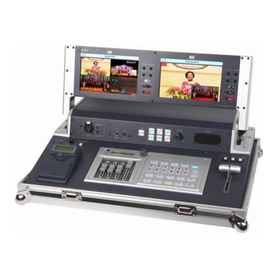
- Page 1 Hand Carry Studio (ITC-50+DAC-200+TLM-702+SE-500) HS-550...
-
Page 2: Table Of Contents
Rear input options Channel 4 ........................... 16 HS-550 Channel 4 configuration buttons......................17 Computer Display Set Up ..........................17 Recording from the HS-550 with an optional DN-60 ..................18 HS-550 DV port Set Up ............................ 19 DN-60 - A brief Set Up guide ..........................19 DN-60 Connections &... - Page 3 Disclaimer of Product and Services The information offered in this instruction manual is intended as a guide only. At all times, Datavideo Technologies will try to give correct, complete and suitable information. However, Datavideo Technologies cannot exclude that some information in this manual, from time to time, may not be correct or may be incomplete.
-
Page 4: Warnings And Precautions
7. This product should only be operated from the type of power source indicated on the marking label of the AC adapter. If you are not sure of the type of power available, consult your Datavideo dealer or your local power company. -
Page 5: Warranty
Certain parts with limited lifetime expectancy such as LCD Panels, DVD Drives, Hard Drives are only covered for the first 10,000 hours, or 1 year (whichever comes first). Any second year warranty claims must be made to your local Datavideo office or one of its authorized Distributors before the extended warranty expires. -
Page 6: Introduction
Perfect for applications within education, places of worship, internet streaming, event & live staging, conferences, race meetings and many more. The HS-550 is supplied complete in a practical and light weight aluminium carrying case, for easy transport and secure storage. -
Page 7: Overview Hs-550
Overview HS-550 HS-550 Front Panel 1. Audio faders 9. Background color selection/Menu 2. Headphone Socket 10. Border On/Off 3. Audio meters 11. T-Bar 4. Headphone Volume Control 12. Transition Effect preview 5. Video Effect: Quad 13. Main Video Source selectors 6. - Page 8 1. Faders: sliders to control audio levels for the Main audio output mix. These Audio Level pots are the first stage in the audio signal path. Analog audio comes in through the 1/4 inch phone jack and RCA connectors on the rear panel see Rear Panel.
- Page 9 The Headphone volume is controlled by the Headphone volume control (B.). B. Volume Control: controls Headphone level (DN- 60) and HS-550 speaker Level is controlled by the rotary knob. Playback/Record selectors: Used to select which of the (DN-60) PLAY BACK or RECORD.
-
Page 10: Hs-550 Rear Panel
HS-550 Rear Panel 11b 10b 1. DVI / VGA Monitor Output 7. DV Output 2. DVI Input (input Ch4) 8. DC Power input 12V 10A 3. VGA Input (input Ch4) 9. Power On / Off switch 4. Video inputs, Channels 1, 2, 3, 4. - Page 11 5. Microphone input MIC CH2:A ¼” jack connector for a high impedance analog audio source, such as a microphone. MIC inputs 1 and 2: accept ¼” Inch mono plugs, carrying high impedance signals from one or two mono microphones. With high impedance MIC, the longer the cable from microphone to the SE- 500, the more noise is introduced into the signal.
-
Page 12: Monitors
The Left hand Monitor is split into a 4 screen quad labelled PREVIEW and is referred to as a Quad Preview. This Quad Preview shows the video sources connected to the HS-550. To help you match the video shown to a button, or an input, each section of this Quad Preview is labelled;... -
Page 13: Dissolving Or Fading Between Sources
Main Source row. Pressing a Sub Source button may not cause an immediate change to the HS-550’s main output or Program monitor. The selected Sub Source button (illuminated Yellow) only identifies which video input source will be next shown when using the T-Bar. -
Page 14: List Of Wipe Transitions And Parameters (Suitable For Photocopying)
List of Wipe transitions and parameters (suitable for photocopying) Any Wipe works in conjunction with the Border control. A represents the current source and B represents the sub source that will replace A during the transition. Vertical wipe, from middle out to left and right sides at the same time. Vertical wipe, from left to right side. -
Page 15: Effects
Effects There are two places on the HS-550 where you can add effects: in the Transition Effects section (15.) and in the Video Effects section (5-8.). Some of these work on a single source, and some need two or four sources to work. -
Page 16: Effects: Quad
Dual channel effects are produced on the source selected in the Main Video Source bus and require a second source, which is always selected in the Sub Video Source bus. Dual channel effects include Picture in Picture. For example, select Main and Sub Video Sources, and then press the PIP (Picture in Picture) button; immediately, on the program monitor, you will see the Sub Video Source in a small window. -
Page 17: Effects: Freeze
HS-550 to include presentations or graphics from a computer or laptop using the VGA or DVI options of channel 4. As well as connecting the VGA or DVI cabling from the computer to the rear of the HS-550 (see 1 or 2 above) you will also need to select the input type using the configuration buttons above the T-Bar of the mixer (see picture on next page). -
Page 18: Hs-550 Channel 4 Configuration Buttons
In order for the HS-550 to see the computer output you may need to extend the computer or laptop desktop to a second monitor using Control Panel as below. When using a laptop you may need to use a function key combination to allow use of the VGA port, much in the same way as using a laptop with a projector. -
Page 19: Recording From The Hs-550 With An Optional Dn-60
(the HS-550) and the presentator’s output is sent to Monitor 1 (the PC’s own monitor). 9. Run the Powerpoint presentation and you should see it playing back on the HS-550 PROGRAM window. 10. Now you can attempt to work the presentation or graphics into your mix, either on its own or with the speaker in a smaller PIP window. -
Page 20: Hs-550 Dv Port Set Up
HS-550 monitor and DV port button back to their original settings before attempting to mix/record again. It is not possible to play 2 DV devices into the HS-550 at the same time this will only cause the external devices to become un-responsive as they are both trying to access the same channel. -
Page 21: Rear Panel
Rear Panel Battery Compartment Cover – Press in gently and slide up to access Camera Mount screw thread – Attach DN-60 camera mount here DV/DVC Pro/HDV i/o Port – Attach 6pin IEEE-1394 cable connector here RS-232 Port – Connect 3.5mm Jack for RS-422 control by computer CF Card Slot 1. -
Page 22: Dn-60 Powering On
Auto power ON/OFF position (DV port button is switched on/off) Manual power OFF position The LCD display panel will show “Datavideo DN-60 Loading…” after a few seconds the Home Display will be shown. The DN-60 is now ready for set up or use as a recorder or playback device. -
Page 23: Cf Card
Ensure your chosen Compact Flash (CF) card is qualified for use with the DN-60. If you are not sure check with your local dealer or Datavideo office. Back up any data to computer that is already on the CF card before inserting the card into the DN-60. -
Page 24: Hs-550 Audio Inputs, Levels, And Meters
HS-550 Audio Inputs, Levels, and Meters Audio Monitoring For output audio monitoring with headphones, set the rotary headphone volume control knob to the center. (4.); to monitor through an amplifier and speakers, push the MASTER fader to -12 in the Audio Faders (1.) section. -
Page 25: Reset
Base Corrector. In fact, they are the proc amp controls of one of the SE-500’s 4 internal TBCs. This is because the HS-550 is built around the SE-500 mixer. At the top of screen you will see 4 different channel numbers, each represent an input from the SE-500 rear panel. -
Page 26: Menu - Output
Control and Color Bar Output. Menu – Output If you change this setting then the Program or DV outputs of the HS-550 may stop working. Please ensure output is set to Y/C, CV, CV and do not set it to YUV, CV. -
Page 27: Se-500 Specifications
SE-500 Mixer Specifications Video Formats Analog Y/C, Composite CCIR601 NTSC and PAL (PAL and NTSC units are separate models) Video Inputs 4 – Composite Video Output 1 – Quad Video source monitoring (Composite) 2 – Composite Audio Inputs 1 – Stereo input (RCA connector) 2 –... -
Page 28: Itc-50 Intercom Controls
ITC-50 Intercom Controls 1. XLR Microphone Socket 5. 1~5 & ALL Channel Buttons 2. Headphone Socket 6. Volume Control 3. Microphone / Headset Socket 7. Built-In Speaker 4. MUTE Button XLR Microphone Socket Combined XLR / ¼” (6.3mm) Jack Microphone Input for either a Condenser or Dynamic Gooseneck Microphone. -
Page 29: Itc-100Sl Slave Unit
ITC-100SL Slave Unit XLR Connection Connects the ITC-100SL to the ITC-100 Base Station. Power, tally and bi-directional audio are all carried through the same CB-3 cable. Call Button Sends a paging message to the ITC-100 Base Station. The channel button will flash orange and there will be an audible tone, each time the button is pressed. -
Page 30: Cable Assignments Headset, Jack Plug And 5Pin Xlr
Cable Assignments Headset, Jack plug and 5pin XLR Please Note: If you only want to extend the reach of the ITC-100SL Belt Pack cabling then Datavideo already sell pre-manufactured XLR cabling for doing this in 20m (CB-3) and 50m (CB-4) lengths. Please ask your local dealer for price and availability of additional CB-3 and CB-4 cables. -
Page 31: Tlm-702
Functions - Front Panel Each monitor has a two color tally light indicator which can be connected to the Datavideo RMC 140, SE500 or similar products. AMBER indicates Cued and RED indicates Live. Each Monitor has individual adjustments for Brightness, Contrast, Color and Tint (Tint is for NTSC only). -
Page 32: Functions - Rear Panel
TLM-702 from other regulated 12V supplies (min 1.5A). 3.5mm Jack Socket for tally light connection. You can connect the tally feed from the Datavideo SE 500, RMC-140, RMC90 or other similar equipment. Each monitor has two composite video inputs, each with a loop-through output. The video input can be PAL or NTSC, the TLM-702 will automatically detect the video standard. -
Page 33: Service & Support
It is our goal to make your products ownership a satisfying experience. Our support staff are available to assist you in setting up and operating your system. Please refer to our web site www.datavideo-tek.com for answers to common questions, support requests or contact your local office below.
Need help?
Do you have a question about the HS-550 and is the answer not in the manual?
Questions and answers