Table of Contents
Advertisement
Quick Links
Advertisement
Table of Contents

Related Manuals for Datavideo HDR-200


Summary of Contents for Datavideo HDR-200
-
Page 1: User Guide
HD HDD Recorder HDR-200 with HS-1000 USER GUIDE Rev 060809 www.datavideo-tek.com... -
Page 2: Table Of Contents
Introduction ----------------------------------------------------------------------------------------------------- 4 Features ----------------------------------------------------------------------------------------------------------- 4 How to Assemble 2.5" HDD in Removable Rack ---------------------------------------------------- 5 Connections & Controls ------------------------------------------------------------------------------------ 6 HDR-200 Front Panel ----------------------------------------------------------------------------------- 6 HDR-200 Rear Panel ------------------------------------------------------------------------------------ 7 Powering On ---------------------------------------------------------------------------------------------------- 8 Menu Options - Overview ----------------------------------------------------------------------------------- 8... -
Page 3: Warnings And Precautions
7. This product should only be operated from the type of power source indicated on the marking label of the AC adapter. If you are not sure of the type of power available, consult your Datavideo dealer or your local power company. -
Page 4: Warranty
Equipment that fails after the warranty period, has been operated or installed in a manner other than that specified by Datavideo, or has been subjected to abuse or modification, will be repaired for time and material charges at the Buyer’s expense. -
Page 5: Packing List
2.5" Removable HDD enclosure with SATA and USB interface for easy file transfer. * N.B. The HDR-200 cannot be operated as a DV Device from a Computer - The AVC Command set is not supported. Also to control the unit via GPI and RS-422 / RS-232 further cabling would be required... - Page 6 3. Slide the PCB and drive module back into the HE-1 enclosure. 4. Re-assemble the HE-1 with the two screws to secure the front cover. 5. Slide HE-1 with drive fitted into HDR-200 then move locking button to the left.
-
Page 7: Connections & Controls
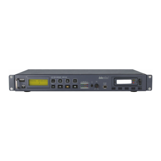
/ off switch is on the rear panel. Display Panel. Displays the status of the HDR-200. The display will show Track Number, timecode, or if the Menu Button is pressed the Menu Display. -
Page 8: Rear Panel
2 channels XLR Balanced Audio input & output. This audio will also be passed to the HDMI and HD-SDI outputs. The GPI socket can be used for simple external control. The HDR-200 can accept pulse or level trigger inputs, which can trigger record or playback or pause commands. -
Page 9: Powering On
Menu Options The HDR-200 is a menu driven unit; there are 19 menus which are used to initially set up the unit. The menu settings are non-volatile (they are stored even when the unit is switched off). So many of the settings, such as date and time, you will only need to set once. - Page 10 See GPI Mode & Function Menus for more details. SET DATE & TIME Sets the date and time on the HDR-200; the setting is non-volatile so it is stored even when the unit is powered off. See Set Date & Time Menu for more details.
-
Page 11: Hdd Mode Menu
PC or MAC. The files appear in the root directory of the HDR-200 hard disk, and are numbered with the track number that appears in the LCD display when you are recording or playing back the track. -
Page 12: Video Input Source Menu
Video Input Source Menu The Video Input Source Menu sets the analogue input mode of the HDR-200. The HDR-200 has YPbPr and SDI analogue inputs. To select the Video Input Source: Press the Menu Button, to enter menu mode Press the FWD (►►) Button to navigate the menus until VIDEO INPUT SOURCE is displayed. -
Page 13: Set Mpeg2 Bit Rate Menu
SET MPEG2 BIT RATE Menu To select the MPEG2 encoding BIT RATE: Press the Menu Button, to enter the menu mode Press the FWD (►►) Button to navigate the menus until SET MPEG2 BIT RATE is displayed Press the Next (▲) Button(right) to enter the SET MPEG2 BIT RATE menu Use the FWD(►►) or REW(◄◄) Button to select the desire bit rates (20,25,30,35,40,45,50,55,60 Mbps) To confirm your selection and exit the menu press the Next (▲) Button(right). -
Page 14: Set 1080I H-Res. Menu
SET 1080i H-RES. Menu Press the Menu Button, to enter the menu mode Press the FWD (►►) Button to navigate the menus until SET 1080i H-RES. is displayed. Press the Next (▲) Button(right) to enter the SET 1080i H-RES. menu Press the FWD (►►) Button to select either 1440 or 1920. -
Page 15: Gpi Mode & Function Menus
GPI Mode & Functions Menus The HDR-200 can be set to receive either pulse or level GPI triggers, which can be set to activate Play / Pause or Rec / Pause. To select the GPI Mode: Press the Menu Button, to enter menu mode Press the FWD (►►) Button to navigate the menus until SET GPI TRIGGER MODE is displayed... -
Page 16: Set Date & Time Menu
Set Date & Time Menu To set the Date & Time on the HDR-200 Press the Menu Button, to enter menu mode Press the REW (◄◄) Button to navigate the menus until SET DATE & TIME is displayed Press the Next (▲) Button(right) to enter the SET Date & Time menu You will see a flashing cursor on the date value. -
Page 17: Erase Track Menu
HDR-200 this will result in a conflict, which will mean that the HDR-200 output is blocked. Please change the output channel I.D. of the HDR-200 to solve the problem. The default output channel of the HDR-200 is 1, selecting any other value, between 0 - 63 will overcome the conflict. -
Page 18: Hdd Surface Scan Menu
Press the Next (▲) Button(right) to exit the surface scan. A txt file called Result will have been created in the root directory of the HDR-200 HDD, this can be accessed via a PC, by connecting the HDR-200 as a HDD. -
Page 19: Playing A M2T Track
(►II) Button. It is also possible to set the HDR-200 to loop play. In loop play the track will seamlessly looped until stopped. To set up loop play press the Menu Button to enter menu mode and then the FWD (►►) Button until SETUP LOOP PLAY is displayed. -
Page 20: Connecting To A Computer
The track you have selected on the HDR-200 is empty. The counter next to the TrackNo on the LCD display should b showing 00:00:00:00. There is some available space on the HDR-200 Hard Disk - Go to the FREE SPACE Menu and check that the HDR-200 is not full. -
Page 21: Connecting To A Pc
Folder to View Files. The drive should also appear in My Computer as an internal HDD. Once connected the HDR-200 can be used just like any HDD. You can select the required files and drag and drop them to the required destination. - Page 22 SBP2 Device and click on Stop. A second dialog box will appear. Select Datavideo HDD IEEE SBP2 Device and click on OK. After a few seconds a “Safe To Remove Hardware” message should appear above the Taskbar. You can then disconnect the HDR-200.
-
Page 23: Connecting To A Mac
Press the Next (▲) Button(right) again to confirm, after a few seconds HDD Mode will be enabled The MAC should see the HDR-200 as a HDD and the files will appear in the root directory of the drive. You can select the required files and drag and drop them to the required destination. -
Page 24: Interface Overview
HDR-200 RS-422 Protocol Reference V1.0 1. Interface Overview Conforming to EIA RS-422A. Full duplex communications channel is utilized. Data is transmitted asynchronously, bit serial, word serial with data exchange between devices. Standard transmission rate on the interface bus is 38400 bits per seconds (bps) ... -
Page 25: Connector Pin Assignment
(=70) CHECKSUM = “70” Therefore, the complete command is “61.0C.03.70” 3. Connector Pin Assignment Interface : 9 pin D-Sub female The pin assignment of the Controller and HDR-200 is shown in the following table: Signal Controller HDR-200 Frame Ground Frame Ground... -
Page 26: Communication Protocol
3. The CONTROLLER must transmit of bytes in a COMMAND block for with intervals less than 10 milliseconds. If a DEVICE (HDR-200) detects an interruption of a byte in a COMMAND block that exceeds 10 milliseconds, it executes a TIME-OUT error sequence, voids the receiving COMMAND block, and transmit a NAK (TIME OUT). - Page 27 6. Detailed Description of Commands 00h 11h : DEVICE TYPE REQUEST Send: 00h 11h 11h Return: 12h 11h B0h 01h D4h (HDR-200) 20h 00h : STOP Send: 20h 00h 20h Return: 10h 01h 11h 20h 01h : PLAY Send: 20h 01h 21h...
- Page 28 The “00h 11h : DEVICE TYPE REQUEST” command is used for asking the specifications of the HDR-200 used as DEVICE. When the DEVICE receives this command, it attaches 2- bytes specification data to “12h 11h : DEVICE TYPE” and sends the information to the CONTROLLER.
- Page 29 8. Status return data 7xh 20h : Bit 7 Bit 6 Bit 5 Bit 4 Bit 3 Bit 2 Bit 1 Bit 0 Data 0 Busy Disk Out Hardware Local Error Enable Data 1 Standby Stop Eject Rewind Fast Record Play Forward Data 2...
-
Page 30: Specification
Specifications • 3x BNC connector for HD-YUV input • 1x BNC connector for HD-SDI input Inputs Interface • 2x XLR connector for audio input • 3x BNC connector for HD -YUV output • 2x BNC connector for HD-SDI output • 1x BNC connector for HD-SDI pass through output Outputs Interface •... -
Page 31: Service And Support
It is our goal to make your products ownership a satisfying experience. Our supporting staff is available to assist you in setting up and operating your system. Please refer to our web site www.datavideo-tek.com for answers to common questions, support requests or contact your local office below.
Need help?
Do you have a question about the HDR-200 and is the answer not in the manual?
Questions and answers