Table of Contents
Advertisement
Quick Links
Download this manual
See also:
Instruction Manual
Advertisement
Table of Contents

Related Manuals for Datavideo HS-2000 Hand Carried Studio


Summary of Contents for Datavideo HS-2000 Hand Carried Studio
- Page 1 Mobile Video Studio HS-2000 Hand Carried Studio (SE-2000+ITC-50+TLM-170) Instruction Manual www.datavideo-tek.com...
-
Page 2: Table Of Contents
HS-2000 Monitor PIP Menu ........................28 Special Feature Menu ..........................29 System Information Menu ........................31 ITC-100SL Slave Unit ............................. 32 Optional Datavideo Accessory Items for the HS-2000 ................... 33 HS-2000 (SE-2000) Specification ........................34 ITC-50 Specification ............................35 ITC-100SL Specification ..........................35 Monitor Specification ............................ -
Page 3: Warnings And Precautions
Disclaimer of Product and Services The information offered in this instruction manual is intended as a guide only. At all times, Datavideo Technologies will try to give correct, complete and suitable information. However, Datavideo Technologies cannot exclude that some information in this manual, from time to time, may not be correct or may be incomplete. -
Page 4: Warranty
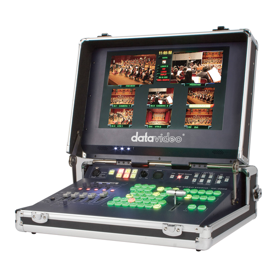
Editing, monitoring and communication are all in one easy to transport box. The Datavideo HS-2000 mobile video studio is a ready to go solution; it saves a lot of your valuable time when setting up or breaking down in the field. To get the most out of your HS-2000 please read this user... -
Page 5: Unpacking The Hs-2000
Unpacking the HS-2000 Place the HS-2000 on a stable, flat surface, such as a desk with the two locks of the case facing towards you. Unlock the two locks and lift the lid. - Page 6 Open the locking catches on both sides and remove the rear connections cover. You can now connect source cabling, output cabling, AC power and the ITC-100SL belt pack cabling to this rear panel.
-
Page 7: Hs-2000 Connections & Controls
HS-2000 Connections & Controls Keyboard 1. Audio input selectors / Level Controls 8. CUT & TAKE 2. Audio level indicator & Audio monitor 9. T-Bar 3. Menu Controls 10. Main / Sub Source selection buttons 4. Logo & Clock buttons 11. -
Page 8: Keyboard Controls
Keyboard Controls Audio Input Source Selectors and Level Controls This section of the HS-2000 controls which audio input channel (CH1~CH4) will be sent to the Audio Bus and its associated Fader. This row of audio channel selection buttons has LEDs built in to show which input channel is active. - Page 9 PIP / KEY LUMA PVW and LUMA PGM A Luma key can be performed between 2 inputs and the result sent to the PVW (Preview) and PGM (Program) display channels. See Setting up a LUMA Key (Page 21) If you want to enable the PIP function, you must first press the SET key, then press the PIP PVW key and then select the Sub Source button for the PIP window.
- Page 10 T-Bar The T-Bar is used to carry out a manual transition such as a wipe, fade, mix or key. When it has travelled as far as it can go the transition is complete. How to calibrate the T-bar: 1. Turn off the HS-2000 power, and push the T-Bar up as far as it can go to its Top or AIR position then move the T-Bar back down by 2mm.
-
Page 11: Rear Panel
Headphone Socket (Intercom) ¼ “/ 6.3mm Stereo Headphone Socket for conventional headphones. Plugging in headphones will disable the built-in ITC-50 Intercom speaker Microphone / Headset Socket (Intercom) 3.5mm Stereo Socket for combined Microphone Headset. Plugging in a Microphone / Headset will disable the built-in speaker and the XLR Microphone Input. -
Page 12: Rear Panel Connections
DVI-D IN DVI-I Signal Input (Digital Input 5). TALLY Tally out socket. This supplies tally light information to the Datavideo ITC-50 system (not supplied). RS-232 9-pin serial port standard RS-232 interface. Connect PC to update firmware, Logos or Mixer Configuration. -
Page 13: Main Source And Sub Source Rails
AUDIO OUT Supports XLR Balanced Audio output. Stereo Mono switch can be used to select a stereo output or a dual Mono output. Stereo output will show CH1 & CH3 on XLR A and CH 2 & CH 4 on XLR B. Mono output will show the same mono audio across both XLR outputs A and B. -
Page 14: Transition Effects
Transition Effects WIPE from upper Left corner to lower Right corner of screen WIPE from Left to Right of screen WIPE from Top to Bottom of screen WIPE from upper Right corner to lower Left corner of screen WIPE from outside edge of screen to centre of screen WIPE from Left and Right hand sides into the centre of the screen. -
Page 15: System Configuration Menu
System Configuration Menu Menu and Navigation Press the MENU button in the Function section of the HS-2000’s keyboard to enter the System Configuration Menu. The menu will be displayed on the HS-2000’s Multi Preview output as below. Press the UP, DOWN, LEFT and RIGHT arrow buttons to highlight or select a menu option. Then use the UP and DOWN arrow buttons to change the value of the selected item or option. -
Page 16: Pip Setting
PIP SETTING Press the MENU button and highlight the PIP SETTING. Press the arrow buttons to select an item and press the ENT to confirm the setting. X- POSITION: adjustment range from 0 to +102 (when MODE SETTING is 1080i) Y- POSITION: adjustment range from +113 to 0 (when MODE SETTING is 1080i) X- POSITION: adjustment range from 0 to +70 (when MODE SETTING is 720p) Y- POSITION: adjustment range from +77 to 0 (when MODE SETTING is 720p) -
Page 17: Mode Setting
MODE SETTING Press the MENU button and highlight the MODE SETTING. Press the arrow buttons to select an item. Press the right arrow button, press the up arrrow button, and press the ENT button to confirm the setting. This Mode setting is used to adjust the HD input mode. HD Mode values can be 1080/50i - 1080/60i - 1080/59.94i - 720/50p - 720/60p or 720/59.94p MASTER USER SETTING: When selected, the values for the above are copied from the BASIC profile. -
Page 18: Background
BACKGROUND Press the MENU button and highlight the BACKGROUND option. Press the arrow buttons to select an item and press the ENT to confirm the setting. This option sets the background colour of the Multi Preview screen – options are Black, Grey or Blue. -
Page 19: Audio Inputs And Levels
Audio Inputs and Levels Analogue audio comes into the HS-2000 through the XLR connectors on the rear panel (as above diagram). The HS-2000 supports four XLR Balanced Audio Input channels. NOTE: Audio cannot be de-embedded by the HS-2000 from a HD-SDI input and Audio will not be embedded into the HS-2000’s HD-SDI PGM outputs. -
Page 20: Hs-2000 Configuration Utility
TGA 32bit or BMP 24bit file with a clear Alpha Channel background. The graphics software to create your Logo image is not supplied by Datavideo. * We recommend that you only use the HS-2000 Configuration Utility to add/write new Logos as changing any... -
Page 21: Setting Up A Luma Key Overlay With Power Point
Setting up a Luma Key overlay with Power Point The HS-2000 has 5 inputs. Input 5 is DVI only and this can be used to connect a DVI-D cable from a computer’s monitor/graphics card. The PC graphics card will need 2 connections 1 for the PC monitor and a spare DVI-D connection to go to input 5 on the HS-2000. -
Page 22: Hd-Sdi Cabling Advice
SDI signal that complies with the SMPTE 292M standard at 1.5 Gbps. Datavideo Taiwan have determined that single BNC SDI cable (5CFB) runs of up to 100m should be possible with this unit before the signal would need to be re-clocked or repeated. -
Page 23: How To Update Hs-2000 Mixer Firmware
How to update HS-2000 mixer firmware From time to time Datavideo may release new firmware to either add new features or to fix reported bugs in the current mixer firmware. Customers can update the mixer firmware themselves if they wish or they can contact their local dealer or reseller for assistance should they prefer this method. - Page 24 Now turn the mixer ON. Once the application discovers the mixer it will check the firmware on the mixer and report if it needs updating. Click NEXT to start the update. You will be asked to confirm that you want to proceed click YES.
-
Page 25: Intercom & Monitor Control Panel
Intercom & Monitor Control Panel ITC-50 Intercom Controls Monitor Controls 1. XLR Microphone Socket 6. Source Select 2. MUTE Button 7. Aspect Ratio & PIP Button 3. 1~5 & ALL Channel Buttons 8. Menu Navigation Buttons 4. Volume Control 9. Volume Control & Audio 5. -
Page 26: Monitor Menu Options
Monitor Controls Source Select Buttons Select the type of input you are using - HDMI, PREVIEW, PROGRAM The active input will be indicated by a red LED on the Source Button Aspect Ratio Button Sets the Aspect Ratio to 16:9 / 4:3 PIP Button Activates Picture in Picture Mode - See PIP Menu for more details. -
Page 27: Colour Processor
PIP Feature Setting Special Feature Setting System Information Colour Processor The first menu to be displayed is the Colour Processor Menu. To access the Colour Processor Menu press enter, the Brightness setting will be highlighted. -
Page 28: Hs-2000 Monitor Pip Menu
To adjust the Brightness press Enter again. An adjustment bar will appear at the bottom of the screen. Use the Up / Down buttons to change the setting and then press Enter to store the new value and return to the main menu. -
Page 29: Special Feature Menu
Use the Up / Down buttons to navigate the available options. You can choose: PIP Mode Large PIP Small PIP PIP Position Bottom-Right Top-Left Top-Right Bottom Left You can also choose: PIP Main Source COMP. - Component HDMI PIP Sub Source COMP. - Page 30 Once the setting is highlighted press the ENTER button again to highlight the options, and then use the UP / DOWN buttons to select the required value, and press ENTER once more to accept the new value. In the Special Feature Menu you can choose: Frame Ratio - This will display a “Safe Area”...
-
Page 31: System Information Menu
System Information Menu The System Information Menu displays the Firmware Version of the monitor, and offers a Factory Reset option, which will return all the settings of the monitor to the factory defaults. To reset the monitor press the ENTER button, then press the up/down button so that Factory Reset is highlighted, and then press ENTER again to highlight the options column. -
Page 32: Itc-100Sl Slave Unit
ITC-100SL Slave Unit XLR Connection Connects the ITC-100SL to the ITC-50 Base Station. Power, tally and bi-directional audio are all carried through the same cable. Call Button Sends a paging message to the ITC-50 Base Station. The channel button will flash orange and there will be an audible tone, each time the button is pressed. -
Page 33: Optional Datavideo Accessory Items For The Hs-2000
Datavideo have a number of accessory products which will allow you to get the most from your new HS-2000. Please speak to your local dealer or visit the website for your local Datavideo office for more details on these and other products. -
Page 34: Hs-2000 (Se-2000) Specification
HS-2000 Specification (SE-2000) • 4x BNC connector for HD -SDI input Inputs • 2x DVI connector for DVI-D input (1x DVI-D input is collective with SDI#4 channel) • 2x HD-SDI output, 1x HD-YUV output Outputs • Video delay through the mixer 1 Frame or less •... -
Page 35: Itc-50 Specification
ITC-50 Specification 3.5mm Stereo Jack Socket for combination Headphone / Microphone MIC / HEADSET Headset Impedance 8~600 ohms 100mW(min) INPUTSN ¼” (6.3mm) Stereo Headphone Socket HEADPHONE & Headset Impedance 8~600 ohms 100mW(min) OUTPUTS 3 Pin XLR / ¼” (6.3mm) Jack Microphone Socket Switchable Condenser / MICROPHONE Dynamic Input. -
Page 36: Service & Support
It is our goal to make your products ownership a satisfying experience. Our support staff are available to assist you in setting up and operating your system. Please refer to our web site www.datavideo-tek.com for answers to common questions, support requests or contact your local office below.
Need help?
Do you have a question about the HS-2000 Hand Carried Studio and is the answer not in the manual?
Questions and answers