
Related Manuals for Datavideo HS-2000


Summary of Contents for Datavideo HS-2000
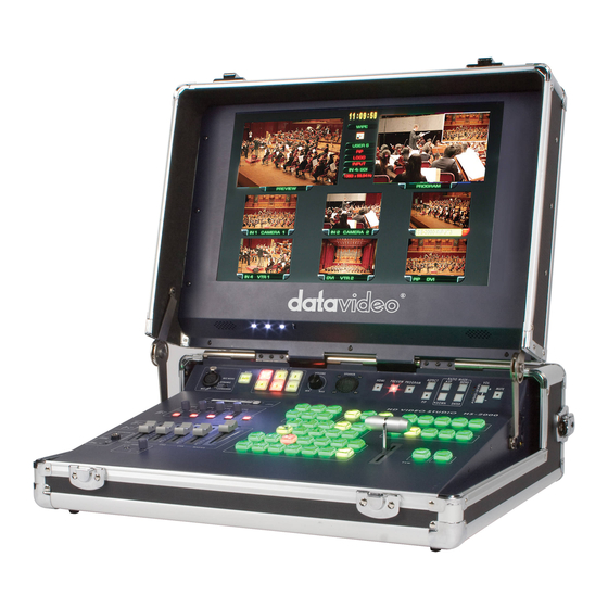
- Page 1 Mobile Video Studio HS-2000 Hand Carried Studio (SE-2000+ITC-50+TLM-170) Instruction Manual www.datavideo-tek.com...
-
Page 2: Table Of Contents
Disposal ..............................6 What is in the Package ..........................6 Introduction ..............................6 Unpacking the HS-2000 ..........................7 HS-2000 Connections & Controls ........................ 9 Keyboard ..............................9 Keyboard Controls ..........................10 Audio Input Source Selectors and Level Controls ................10 Audio LED Meters .......................... - Page 3 HS-2000 Monitor PIP Menu ........................40 Special Feature Menu ..........................41 System Information Menu ........................43 ITC-100SL Slave Unit ..........................44 Optional Datavideo Accessory Items for the HS-2000 ................45 HS-2000 (SE-2000) Specification ....................... 46 ITC-50 Specification ............................ 47 ITC-100SL Specification ..........................47 Monitor Specification ..........................
- Page 4 Disclaimer of Product and Services The information offered in this instruction manual is intended as a guide only. At all times, Datavideo Technologies will try to give correct, complete and suitable information. However, Datavideo Technologies cannot exclude that some information in this manual, from time to time, may not be correct or may be incomplete.
-
Page 5: Warnings And Precautions
7. This product should only be operated from the type of power source indicated on the marking label of the AC adapter. If you are not sure of the type of power available, consult your Datavideo dealer or your local power company. -
Page 6: Warranty
The Datavideo HS-2000 mobile video studio is a ready to go solution; it saves a lot of your valuable time when setting up or breaking down in the field. To get the most out of your HS-2000 please read this user... -
Page 7: Unpacking The Hs-2000
Unpacking the HS-2000 Place the HS-2000 on a stable, flat surface, such as a desk with the two locks of the case facing towards you. Unlock the two locks and lift the lid. - Page 8 Open the locking catches on both sides and remove the rear connections cover. You can now connect source cabling, output cabling, AC power and the ITC-100SL belt pack cabling to this rear panel.
-
Page 9: Hs-2000 Connections & Controls
HS-2000 Connections & Controls Keyboard 1. Audio input selectors / Level Controls 8. CUT & TAKE 2. Audio level indicator & Audio monitor 9. T-Bar 3. Menu Controls 10. Main / Sub Source selection buttons 4. Logo & Clock buttons 11. -
Page 10: Keyboard Controls
System Configuration Menu Press the Menu button in the HS-2000 function section to enter the System Configuration Menu. Press the up, down, left, and right arrow buttons to navigate the menu options and to change values. Use the ENT button to save and confirm any setting that has been amended. -
Page 11: Pip / Key
PIP / KEY LUMA PVW and LUMA PGM A Luma key can be performed between 2 inputs and the result sent to the PVW (Preview) and PGM (Program) display channels. See Setting up a LUMA Key (Page 21) If you want to enable the PIP function, you must first press the SET key, then press the PIP PVW key and then select the Sub Source button for the PIP window. -
Page 12: T-Bar
How to calibrate the T-bar: 1. Turn off the HS-2000 power, and push the T-Bar up as far as it can go to its Top or AIR position then move the T-Bar back down by 2mm. 2. Press and hold in the SET and SUB SOURCE 1 buttons at the same time. -
Page 13: Headphone Socket (Intercom)
Headphone Socket (Intercom) ¼ “/ 6.3mm Stereo Headphone Socket for conventional headphones. Plugging in headphones will disable the built-in ITC-50 Intercom speaker Microphone / Headset Socket (Intercom) 3.5mm Stereo Socket for combined Microphone Headset. Plugging in a Microphone / Headset will disable the built-in speaker and the XLR Microphone Input. -
Page 14: Rear Panel Connections
DC INPUT Connect the supplied AC adaptor to this DC Input socket. POWER Switches the power On / Off. MONITOR HDMI IN The HS-2000 provides a useful connection for confidence monitoring HDMI sources location. However, this connection cannot be mixed. Instead use a DAC-9 to convert the HDMI source to HD-SDI and then the source can be mixed via inputs 1~4. -
Page 15: Main Source And Sub Source Rails
Mono output will show the same mono audio across both XLR outputs A and B. AUDIO IN The HS-2000 supports four XLR Balanced Audio Input channels. There are two kinds of switches under AUDIO IN: LINE/MIC switch is used to set the audio as LINE in or MIC in. -
Page 16: Transition Effects
Transition Effects WIPE from upper Left corner to lower Right corner of screen WIPE from Left to Right of screen WIPE from Top to Bottom of screen WIPE from upper Right corner to lower Left corner of screen WIPE from outside edge of screen to centre of screen WIPE from Left and Right hand sides into the centre of the screen. -
Page 17: System Configuration Menu
System Configuration Menu Menu and Navigation Press the MENU button in the Function section of the HS-2000’s keyboard to enter the System Configuration Menu. The menu will be displayed on the HS-2000’s Multi Preview output as below. Press the UP, DOWN, LEFT and RIGHT arrow buttons to highlight or select a menu option. Then use the UP and DOWN arrow buttons to change the value of the selected item or option. -
Page 18: Pip Setting
If you want to enable the PIP function, you must first press the SET key in the PIP / KEY section of the HS-2000 keyboard, then press the PIP PVW key and then select the Sub Source channel required for the PIP window. -
Page 19: Mode Setting
Press the arrow buttons to select an item and press the ENT to confirm the setting. This mode is used to return the HS-2000 BASIC profile (USER 0) to its factory default settings. If the BASIC profile is changed then any USER profiles (1 ~ 5) linked to BASIC will also be changed. -
Page 20: Background
Press the arrow buttons to select an item and press the ENT to confirm the setting. This mode is used to set the clock within the HS-2000. The current Clock value is displayed in between the PREVIEW and PROGRAM windows of the Multi Preview Display. -
Page 21: Audio Inputs And Levels
Audio Inputs and Levels Analogue audio comes into the HS-2000 through the XLR connectors on the rear panel (as above diagram). The HS-2000 supports four XLR Balanced Audio Input channels. NOTE: Audio cannot be de-embedded by the HS-2000 from a HD-SDI input and Audio will not be embedded into the HS-2000’s HD-SDI PGM outputs. -
Page 22: Hs-2000 Configuration Utility
Once downloaded, run the install wizard and follow the on-screen prompts. The software installation will leave an Icon on the PC desktop as above. With the HS-2000 connected to the PC via an RS-232 cable, the initial utility screen will be displayed as above, when the program is launched. -
Page 23: Setting Up A Luma Key Overlay With Power Point
Setting up a Luma Key overlay with Power Point The HS-2000 has 5 inputs. Input 5 is DVI only and this can be used to connect a DVI-D cable from a computer’s monitor/graphics card. The PC graphics card will need 2 connections 1 for the PC monitor and a spare DVI-D connection to go to input 5 on the HS-2000. -
Page 24: Hd-Sdi Cabling Advice
SDI signal received. The signal is attenuated because part of it is reflected back and does not make it to the receiver (HS-2000 for example); it is also distorted because the reflected signal mixes with the original signal causing it to distort as well as adding to the noise floor. -
Page 25: How To Update Hs-2000 Mixer Firmware
How to update HS-2000 mixer firmware From time to time Datavideo may release new firmware to either add new features or to fix reported bugs in the current mixer firmware. Customers can update the mixer firmware themselves if they wish or they can contact their local dealer or reseller for assistance should they prefer this method. - Page 26 Now turn the mixer ON. Once the application discovers the mixer it will check the firmware on the mixer and report if it needs updating. Click NEXT to start the update. You will be asked to confirm that you want to proceed click YES.
-
Page 27: Se-2000 Rs-232 Remote Control Protocol
SE-2000 RS-232 Remote Control Protocol Communication diagram Control Interface Interface RS232 Baud Rate 115200 Data bits Parity None Stop bits Pin Assignment D-Sub 9pin Female The pin assignment of the Host Controller and SE-2000 is shown in the following table: Host SE-2000 ... -
Page 28: Crc (Crcl,Crch)
CRC (CRCL,CRCH) Check sum! It is transmitted lower byte first. All the bytes except the last 2 from the block are used to calculate the check sum. There must be 0x0000 after the check sum calculation including the last 2 bytes, if the data have been transmitted error free. - Page 29 unsigned short ComPort_Flag; unsigned short CMD_Length; unsigned char CMD_Buf[128]; void Cal_Checksum(void) int i; unsigned char crc_lo,crc_hi; unsigned char new_crc_lo,new_crc_hi; unsigned char temp; crc_lo=CMD_Buf[CMD_Length-2]; crc_hi=CMD_Buf[CMD_Length-1]; for(i=0;i<(CMD_Length-2);i++) temp=crc_lo^CMD_Buf[i]; new_crc_hi=CRC16_TABLE_HI(temp); // Reference to Table 1 new_crc_lo=CRC16_TABLE_LO(temp)^crc_hi; // Reference to Table 2 crc_lo=new_crc_lo; crc_hi=new_crc_hi; CMD_Buf[CMD_Length-2]=crc_lo;...
-
Page 30: Table 1. Lower Crc Byte Calculation Coefficients.(Hex)
Table 1. Lower CRC byte calculation coefficients.(Hex) 000h 0c1h 081h 040h 001h 0c0h 080h 041h 001h 0c0h 080h 041h 000h 0c1h 081h 040h 001h 0c0h 080h 041h 000h 0c1h 081h 040h 000h 0c1h 081h 040h 001h 0c0h 080h 041h 001h 0c0h 080h 041h 000h 0c1h 081h 040h 000h 0c1h 081h 040h 001h 0c0h 080h 041h 000h 0c1h 081h 040h 001h 0c0h 080h 041h 001h 0c0h 080h 041h 000h 0c1h 081h 040h... -
Page 31: Table 2. Higher Crc Byte Calculation Coefficients.(Hex
Table 2. Higher CRC byte calculation coefficients.(Hex) 000h 0c0h 0c1h 001h 0c3h 003h 002h 0c2h 0c6h 006h 007h 0c7h 005h 0c5h 0c4h 004h 0cch 00ch 00dh 0cdh 00fh 0cfh 0ceh 00eh 00ah 0cah 0cbh 00bh 0c9h 009h 008h 0c8h 0d8h 018h 019h 0d9h 01bh 0dbh 0dah 01ah 01eh 0deh 0dfh 01fh 0ddh 01dh 01ch 0dch 014h 0d4h 0d5h 015h 0d7h 017h 016h 0d6h 0d2h 012h 013h 0d3h 011h 0d1h 0d0h 010h... -
Page 32: Table 3. Command Type
Table 3. Command Type COM (Hex) ARG (Hex) Description Sub source: Set SDI input port 1 Sub source: Set SDI input port 2 Sub source: Set SDI input port 3 Sub source: Set SDI input port 4 Sub source: Set SDI input port 5 Sub source: Set Black Screen Sub source: Set Colour Bar Main source: Set SDI input port 1... -
Page 33: Table 4. Response Code
PIP source: Set SDI input port 1 PIP source: Set SDI input port 2 PIP source: Set SDI input port 3 PIP source: Set SDI input port 4 PIP source: Set SDI input port 5 PIP display on Sub source PIP turn off on Sub source PIP display on Main source PIP turn off on Main source... - Page 34 Table 5. Status Code (41 Bytes , reference to page 34 & 35) Byte 1: Byte 2: Byte 3: Byte 4: Current_User_Number Input A Input B PIP_Input Byte 5: Byte 6: Byte 7: Byte 8: Effect Speed Speed_Value_0 Speed_Value_1 Byte 9: Byte 10: Byte 11: Byte 12:...
- Page 35 Current_User_Number – current user number (0…5), number 0 corresponds to the Master User which other the other users settings and adjustments can be linked to. Input_A, Input_B, PiP_Input – input number currently switched to the multiplexor’s Line A, multiplexor’s Line B and PiP shaper input; Effect –...
- Page 36 Inp_3_Mode – the current input 3 mode, 0 – SDI, 1 – DVI; Link_Flags – Master user settings link flags, it may be unlinked(value 0) or linked(value1) to the corresponding basic parameter: bit 7 – input 0 settings link flag (brightness, contrast, saturation), bit 6 –...
-
Page 37: Intercom & Monitor Control Panel
Intercom & Monitor Control Panel ITC-50 Intercom Controls Monitor Controls 1. XLR Microphone Socket 6. Source Select 2. MUTE Button 7. Aspect Ratio & PIP Button 3. 1~5 & ALL Channel Buttons 8. Menu Navigation Buttons 4. Volume Control 9. Volume Control & Audio 5. -
Page 38: Monitor Controls
Monitor Controls Source Select Buttons Select the type of input you are using - HDMI, PREVIEW, PROGRAM The active input will be indicated by a red LED on the Source Button Aspect Ratio Button Sets the Aspect Ratio to 16:9 / 4:3 PIP Button Activates Picture in Picture Mode - See PIP Menu for more details. -
Page 39: Colour Processor
PIP Feature Setting Special Feature Setting System Information Colour Processor The first menu to be displayed is the Colour Processor Menu. To access the Colour Processor Menu press enter, the Brightness setting will be highlighted. -
Page 40: Hs-2000 Monitor Pip Menu
The HS-2000 Monitor PIP Menu allows you to adjust the appearance of the picture in picture on the HS-2000 monitor only. Please see pages 9 and 16 of this manual if you wish to use a PIP effect within your HS-2000 mixed PGM output. -
Page 41: Special Feature Menu
Use the Up / Down buttons to navigate the available options. You can choose: PIP Mode Large PIP Small PIP PIP Position Bottom-Right Top-Left Top-Right Bottom Left You can also choose: PIP Main Source COMP. - Component HDMI PIP Sub Source COMP. - Page 42 Once the setting is highlighted press the ENTER button again to highlight the options, and then use the UP / DOWN buttons to select the required value, and press ENTER once more to accept the new value. In the Special Feature Menu you can choose: Frame Ratio - This will display a “Safe Area”...
-
Page 43: System Information Menu
System Information Menu The System Information Menu displays the Firmware Version of the monitor, and offers a Factory Reset option, which will return all the settings of the monitor to the factory defaults. To reset the monitor press the ENTER button, then press the up/down button so that Factory Reset is highlighted, and then press ENTER again to highlight the options column. -
Page 44: Itc-100Sl Slave Unit
ITC-100SL Slave Unit XLR Connection Connects the ITC-100SL to the ITC-50 Base Station. Power, tally and bi-directional audio are all carried through the same cable. Call Button Sends a paging message to the ITC-50 Base Station. The channel button will flash orange and there will be an audible tone, each time the button is pressed. -
Page 45: Optional Datavideo Accessory Items For The Hs-2000
Optional Datavideo Accessory Items for the HS-2000 Datavideo have a number of accessory products which will allow you to get the most from your new HS-2000. Please speak to your local dealer or visit the website for your local Datavideo office for more details on these and other products. -
Page 46: Hs-2000 (Se-2000) Specification
HS-2000 Specification (SE-2000) • 4x BNC connector for HD -SDI input Inputs • 2x DVI connector for DVI-D input (1x DVI-D input is collective with SDI#4 channel) • 2x HD-SDI output, 1x HD-YUV output Outputs • Video delay through the mixer 1 Frame or less •... -
Page 47: Itc-50 Specification
ITC-50 Specification 3.5mm Stereo Jack Socket for combination Headphone / Microphone MIC / HEADSET Headset Impedance 8~600 ohms 100mW(min) INPUTSN ¼” (6.3mm) Stereo Headphone Socket HEADPHONE & Headset Impedance 8~600 ohms 100mW(min) OUTPUTS 3 Pin XLR / ¼” (6.3mm) Jack Microphone Socket Switchable Condenser / MICROPHONE Dynamic Input. -
Page 48: Service & Support
It is our goal to make your products ownership a satisfying experience. Our support staff are available to assist you in setting up and operating your system. Please refer to our web site www.datavideo-tek.com for answers to common questions, support requests or contact your local office below.
Need help?
Do you have a question about the HS-2000 and is the answer not in the manual?
Questions and answers