
Related Manuals for Datavideo HS-2800


Summary of Contents for Datavideo HS-2800
-
Page 1: Quick Start Guide
12-CHANNEL HD/SD HAND CARRIED STUDIO HS-2800 Quick Start Guide Feb-25.2013 P/N: G082060639B1... -
Page 2: Table Of Contents
LOGOS Setup ..........................31 Tally Connector Pin Assignment ...................... 33 GPI OUT Pin Assignment ........................ 35 Dimension ............................36 Specification ............................. 37 HS-2800 Specification........................ 37 ITC-150 (Intercom) Specification ....................38 ITC-100SL Specification ......................38 TLM-170H Specification ......................38 Service & Support ..........................39... -
Page 3: Warnings & Precautions
7. This product should only be operated from the type of power source indicated on the marking label of the AC adapter. If you are not sure of the type of power available, consult your Datavideo dealer or your local power company. -
Page 4: Warranty
Certain parts with limited lifetime expectancy such as LCD Panels, DVD Drives, Hard Drives are only covered for the first 10,000 hours, or 1 year (whichever comes first). Any second year warranty claims must be made to your local Datavideo office or one of its authorized Distributors before the extended warranty expires. -
Page 5: Overview
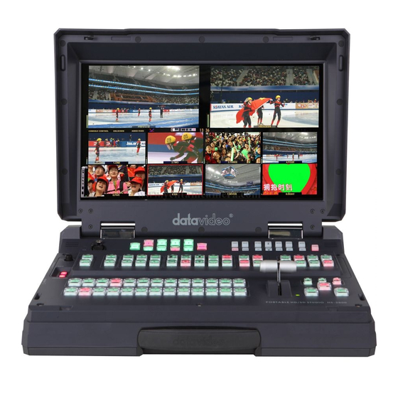
The HS-2800 is an 8 channel 10-bit 1920 x 1080i & cost-effective, broadcast-quality mobile hand carry switcher. Featuring 8 digital, it is designed for live events and TV programs that need to blend a variety of video and audio sources. HS-2800 is light weight, portable and powerful features for mobile switcher solution. -
Page 6: Connections & Controls
Connections & Controls Keyboard 1. Headphone Volume Control 9. CUT / FTB / AUTO TAKE 2. FS & AUX 10. T-BAR 3. AUDUO LEVEL 11. TIME & CLOCK 4. MENU 12. PROGRAM 5. WIPES 13. PRESET 6. LOGO1 & LOGO2 14. - Page 7 CH which user wants to have a background picture on. There are three SDI outputs at the rear of HS-2800 and one of them can be assigned by the user to be AUX-out in order to have a clean source (the video input signal which only bypassing the HS-2800 to the recorder, without any further effects on HS-2800, for effects on a, say a PC.)
- Page 8 If you don’t finish calibrating step, the T-Bar may cause incorrect results. 11. TIME & CLOCK Select HS-2800 TIMER or CLOCK Functions on the screen. 12. PROGRAM Used to select which of the 12 video input channels or background or color bar is...
- Page 9 13. PRESET Used to select which of the 12 video input channels or background or color bar will be transitioned to or used as a PRESET source in an effect. 14. Headphone Socket (HS-2000L or Monitor) ¼ “/ 6.3mm Stereo Headphone Socket for conventional headphones. 15.
-
Page 10: Rear Panel
Rear Panel 1. HD- SDI IN / HDMI IN (12CH) 2. HD- SDI OUT / HDMI OUT / REMOTE CONTROL / CONSOLE 3. ALLY OUT 4. GPI 5. RS-422 6. AUDIO IN 7. MONITOR HDMI IN 8. POWER SWITCH 9. DC IN 10. - Page 11 In 3 is for flash static pictures, and in 4 is to HDMI; All the video/audio input signals will be synchronized. The HS-2800 has 2 modes HD- SDI IN (8CH or 12CH), if you want upgrade 8CH to 12CH please update the HS-2800 firmware.
- Page 12 6. AUDIO IN Supports four channels XLR Balanced Audio Input. 7. MONITOR HDMI IN The HS-2800 provides a useful connection for confidence monitoring of HDMI sources on location. 8. POWER SWITCH Switches the power On / Off. 9. DC IN DC in socket connect the supplied 12V PSU to this socket.
-
Page 13: Intercom & Monitor Control Panel
Intercom & Monitor Control Panel Intercom Function Monitor Function Intercom Function USB Port USB port for LED power supply. XLR Microphone Socket Combined X LR / ¼” (6.3mm) Jack Microphone Input for either a Condenser or Dynamic Gooseneck Microphone. XLR supports Condenser Microphones ¼” (6.3mm) Jack supports Dynamic. ALL Button Opens communication with all channels. -
Page 14: Monitor Function
Monitor Function HDMI, PREVIEW, PROGRAM Select the type of input you are using - HDMI, PREVIEW, PROGRAM. The active input will be indicated by a red LED on the Source Button. When you push the ‘’HDMI’’ button, you select the 17.3" display from the HDMI source input of Rear Panel; It's a full screen display. -
Page 15: Menu Options
Menu Options The TLM-170 H is set up via on screen menus. To display the on screen menu press the MENU button. The menus are navigated using the Up / Down buttons. There are six menus: Video Processor, PIP Feature Setting, Audio Function Setting, Special Function I, Special Function II, System Information. - Page 16 Special Function I The Special Function I Menu has settings for the Frame Ratio, Safe Area, Scan Mode, Central Mark, Cinema Zone Mark and Mask Type…etc. To access the options for the selected setting press enter again, so that the option column is highlighted Use the Up / Down buttons to navigate the available options.
- Page 17 System Information The System Information Menu displays the Firmware Version of the monitor, and offers a Factory Reset option, which will return all the settings of the monitor to the factory defaults. To access the options for the selected setting press enter again, so that the option column is highlighted Use the Up / Down buttons to navigate the available options.
-
Page 18: Transition Effects
Transition Effects Right to Left / Left to Right Top to Bottom / Bottom to UP Middle extend L/R / Middle extend R/L Middle extend U/D / Middle extend D/U Inside Out / Outside In (Round) Inside Out / Outside In (Diamond) Inside Out / Outside In (Square) Upper Left to Lower Right / Lower Right to Upper Left Inverse effect move way. -
Page 19: Setting Sdi Embedded Audio
Setting SDI Embedded Audio Set the HS-2800 SDI Embedded audio, the audio signal must from XLR Audio Input. Please setup your device, as below setup diagram:... -
Page 20: Menu Function Setting
VERSION NUMBER Press the ENTER button into item 1 for VERSION NUMBER. Press the RIGHT button to see the HS-2800 version. INPUT VIDEO SETTINGS Press the ENTER button and then press DOWN button select item 2 for INPUT VIDEO SETTINGS. - Page 21 HDMI IN EMB. AUDIO PAIR Press the ENTER button and then press DOWN button select item 6 for HDMI IN EMB. AUDIO PAIR. Press the RIGHT button and then press UP or DOWN button select INPUT4 / INPUT8 / INPUT12. Press the RIGHT button into your select.
- Page 22 SPEED BUTTONS SETTING Press the ENTER button and then press DOWN button select item 12 for SPEED BUTTONS SETTING. Press the RIGHT button to select SPEED 1 / SPEED 2 / SPEED3. Press the RIGHT button into your select. Press the UP or DOWN button to select your setting. Press the ENTER button to confirm your setting.
- Page 23 BG COLOR SETTING Press the ENTER button and then press DOWN button select item 16 for BG COLOR SETTING. Press the RIGHT and then press UP or DOWN button select your setting. Press the ENTER button to confirm your setting. T-BAR MODE Press the ENTER button and then press DOWN button select item 17 for T-BAR MODE.
-
Page 24: Factory Settings
FACTORY SETTINGS Press the ENTER button and then press DOWN button select item 24 for FACTORY SETTINGS. Press the RIGHT and then press UP button select your setting. Press the ENTER button to confirm your setting. CLOCK SETTINGS Press the ENTER button and then press DOWN button select item 25 for CLOCK SETTINGS. Press the RIGHT button to select X-POSITON / Y-POSITON / SET HOURS / SET MINUTES / CLEAR SECONDS. -
Page 25: Firmware Update Procedure
Firmware Update Procedure 1. Equipment -Ethernet Cable 2. Software -FlashUpdate_SE2800_XXXX_XXXXXX_XXXXXX -SEConfig_Install_XXXXXX 3. System block diagram... - Page 26 4. Software update step - Firmware download can be performed when all the initialized modules have been mounted into the main unit. The initialized keyboard must be connected. Connect the device to PC via LAN and launch LASHUPDATE.exe in the PC. The update utility must establish connection with the device.
- Page 27 - Run FlashUpdate_SE2800_xxxx_xxxxxx_xxxxxx - Turn the device OFF, select Device is connected via Ethernet and press next - Turn the device ON now. - Select Automatically update the device to latest firmware version, and press next - Do you really want to perform firmware update? Select “YES” - Firmware update completed, Click <Finish>...
- Page 28 5. System format standard software settings: - Run FlashUpdate_SE2800_xxxx_xxxxxxxx_xxxxxx - Select” Manually select a firmware version for each chip” - And then press “next step” - Press “ YES ” - Select “ Firmware class “1080i60 / 1080i50 “ - And then press “next step”...
- Page 29 - And then press “next step” ‧ - And then press “next step” - Select “YES“...
- Page 30 - Firmware update is in progress - Firmware update completed “Finish” 6. Run Switcher Configuration Utility - Connection choose Enter IP 192.168.0.211 - Click “Restore factory settings”...
- Page 31 7. Calibrating the T-bar After a firmware update of the switcher it will be necessary to re-calibrate the T-Bar to get it working correctly. Move the T-Bar to its lowest position. Power OFF the SE-2800 switcher. Press and hold down button 1 on both the Program and Preset rows of the switcher’s keyboard.
-
Page 32: Logos Setup
LOGOS Setup Static Logos HS-2800 can store 7 static logos. SEConfig bookmark "Logos". The static Logos to be loaded and written into 1 to 7 memory slots must be 256x128 pixels. This Logos must be created in a graphics software package first as: •... - Page 33 Dynamic Logo SE -2800 can store 1 dynamic logo. SEConfig bookmark "Dynamic Logo". This Logo needs to be created in a graphics software package first as a sequence of up to 75 image. Image size must be 256 x 128 pix, 8 bits/channel Format is the same as for Static Logos: •...
-
Page 34: Tally Connector Pin Assignment
Tally Connector Pin Assignment The output signals from the tally output pins are for lighting the tally lamps, and these outputs are open collector outputs. (D-sub 25-Pin Female) Pin a ssignment Pin No. Signal name Input/Output Description of signal Program 1 Open collector output Tally output of input video Program 1 Program 2... - Page 35 Pin 1 to25 must satisfy the following conditions: Dielectric strength: Max. DC 24V Current: Max. 50mA Example of tally connections (Max. voltage:24V) HS-2800 SE-3000 TALLY OUTPUT (Max. current: 50mA) Tally LED Ground...
-
Page 36: Gpi Out Pin Assignment
GPI OUT Pin Assignment 3.5mm P hone JA CK F emal e GPI_OUT PhoneJACk... -
Page 37: Dimension
Dimension... -
Page 38: Specification
Specification HS-2800 Specification Inputs • 8 inputs, can be configurable to HD SDI, 8 SD SDI, 2 HDMI • 2 BNC output connectors for SDI Outputs • 1 HDMI for Multi-screen (v.1.1) Outputs • RJ-45 for PC Remote controls • 2 BNC for Sync-In and Sync-Out •... -
Page 39: Itc-150 (Intercom) Specification
ITC-150 (Intercom) Specification 3.5mm Stereo Jack Socket for combination Headphone / Microphone MIC / HEADSET Headset Impedance 8~600 ohms 100mW(min) INPUTS ¼” ( 6.3mm ) Stereo Headphone Socket HEADPHONE & Headset Impedance 8~600 ohms 100mW(min) OUTPUTS 3 Pin XLR / ¼” ( 6.3mm ) Jack Microphone Socket Switchable Condenser / Dynamic Input. -
Page 40: Service & Support
It is our goal to make your products ownership a satisfying experience. Our supporting staff is available to assist you in setting up and operating your system. Please refer to our web site www.datavideo-tek.com for answers to common questions, support requests or contact your local office below.
Need help?
Do you have a question about the HS-2800 and is the answer not in the manual?
Questions and answers