Table of Contents
Advertisement
Quick Links
Advertisement
Table of Contents

Related Manuals for Datavideo HS-2200


Summary of Contents for Datavideo HS-2200
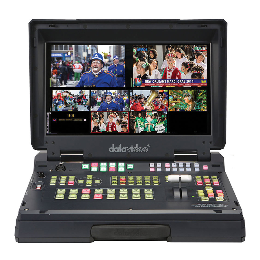
- Page 1 HD/SD 6-CHANNEL PORTABLE VIDEO STUDIO HS-2200 Instruction manual...
-
Page 2: Table Of Contents
Information ............................... 25 Special Function ............................25 Factory Reset ............................26 ....................26 ONITOR FIRMWARE UPDATE PROCEDURE CHAPTER 6 ADVANCED APPLICATIONS ....................27 CG-200 HS-2200 .................. 27 OW TO USE THE SOFTWARE WITH HS-2200 V .......................... 30 IDEO AYERS ......................... 31... - Page 3 SERVICE AND SUPPORT ......................... 48 Disclaimer of Product & Services The information offered in this instruction manual is intended as a guide only. At all times, Datavideo Technologies will try to give correct, complete and suitable information. However, Datavideo Technologies cannot exclude that some information in this manual, from time to time, may not be correct or may be incomplete.
-
Page 4: Fcc Compliance Statement
7. This product should only be operated from the type of power source indicated on the marking label of the AC adapter. If you are not sure of the type of power available, consult your Datavideo dealer or your local power company. -
Page 5: Warranty
Warranty Standard Warranty Datavideo equipment are guaranteed against any manufacturing defects for one year from the date of purchase. The original purchase invoice or other documentary evidence should be supplied at the time of any request for repair under warranty. -
Page 6: Chapter 1 Introduction
Chapter 1 Introduction The HS-2200 is an HD 6 Channel Portable Mobile Cast Video Studio Packed into a durable case, HS-2200 is a convenient and powerful portable video studio. HS-2200 includes a built-in monitor for displaying all incoming input video sources as well as program and preview on a single multi-view screen. -
Page 7: System Diagram
1.2 System Diagram... -
Page 8: Chapter 2 Connections And Controls
Chapter 2 Connections and Controls 2.1 Rear Panel Overview Ethernet Port for PC Control & Updates (TBD) Grounding Terminal RS-232/422 Connector & Mini Switch 1 (TBD) 4pin XLR Power Input Connector GPI Output Connector Mini Switch 2 Ethernet Port for Load File & Firmware TO BELTPACK Updates 3pin XLR Audio Inputs 1~4... - Page 9 AUDIO Outputs Supports two XLR Balanced Audio output channels. Console Port This 9pin D-Sub connector is used to connect the Control Panel / Keyboard to the rear of the HS-2200 Main Processing unit. POWER SWITCH Switches the power On / Off.
- Page 10 The five BNC output connectors are user defined SDI outputs. Each of these SDI outputs has the option to be: 1. Program 2. Program logo free 3. Program logo & titles free 4. Preview 5. Aux1,2,3 or 4 6. Multi screen Note: Please enter the HS-2200 MENU to set the OUTPUT SOURCE.
-
Page 11: Control Panel
#6) can be switched between SDI connector and HDMI port, i.e. the user is allowed to use CH5 and CH6 for either a SDI source or an HDMI source. Note: The CG (picture and animation) data source is connected to the HS-2200 channels 5 and 6 via HDMI cable and edit CG function on the PC. -
Page 12: Keyboard Buttons
Black background – the black background, for use on the Program and Preset row. Background button – assigns a background colour or colour bars for use on the Program and Preset row. Note: Please enter the HS-2200 MENU and select CONSOLE SETTINGS to set the background colour. - Page 13 FS button located at the top left corner of the HS-2200 Control Panel / Keyboard. The FS button allows the user to toggle between the still image of the Frame Store or the live video input also connected to that same video channel.
- Page 14 Use the ENTER button to save and confirm any setting that has been amended. WIPES The HS-2200 has 17 user defined wipe buttons, and a BDR button. All wipes can have an optional colour border applied. The wipe border width and colour are chosen within the menu system.
- Page 15 FUNCTION (F1~F4) PIP Preview and PIP Program When looking at the top right corner of the HS-2200 Control Panel / Keyboard there are four PIP keys. These are labelled Program and Preview. The upper PIP1 and PIP2 keys relate to activating Picture In Picture images on the Program outputs.
- Page 16 LOGO 1 The LOGO 1 and LOGO 2 buttons are used to display pre-selected logos on the HS-2200 Preview and Program outputs. When the button is active the selected logo is shown. These logos are selected from the switcher’s memory and positioned using a menu option.
- Page 17 FREEZE Freeze the program source image or return to live video of the selected program source. T-Bar This performs a manually controlled transition from the current program source to the selected Preset source. The selected transition wipe or dissolve will be used. When the T-Bar has travelled as far as it can go the transition between sources is complete.
- Page 18 Headphone Socket (HS-2000L or Monitor) ¼” / 6.3mm Stereo Headphone Socket for conventional headphones. Headphone Volume Control Control Headphone or Headset volume level. Use the Headphone section to accurately monitor any of the sources (LCD or INTERCOM). LCD / INTERCOM Select headphone &...
-
Page 19: Chapter 3 Switcher Menu Options
HDMI 1 Multi-view output. This section covers the Menu options in the order that they appear on the HS-2200 HDMI 1 Multi-view. These settings may also appear in more detail elsewhere in this instruction manual. Options may vary depending on the firmware version in use. - Page 20 Output 1~6 can be assigned to one of the following: Program Program Logo Free 4. Outputs Sources Output 1~6 Program Logo & DSK Free Preview Aux 1~4 Multi-Screen 5. Aux Selection AUX 1~4 Dynamic Range (dB) 18 or 24 Audio Cross Point Button 1~6 Group 1~4 SDI De-EMB.
- Page 21 GPI Select by CH1~6 (0 = GPI function Input Select disable) 01~99 14. GPI Settings Time Delay Delay time can be set at 01~99 frame LEVEL On / Off 1. MODE PULSE On / Off Ethernet On / Off 15. Remote Control DVIP board On / Off 16.
-
Page 22: Chapter 4 Intercom & Monitor Control Panel
Chapter 4 Intercom & Monitor Control Panel Intercom Function Monitor Function 4.1 Intercom Function USB Port USB port for USB LED Light power supply & 17.3’’ monitor firmware upgrade. XLR Microphone Socket Combined XLR XLR / ¼” (6.3mm) Jack Microphone Input for either a Condenser or Dynamic Gooseneck Microphone. -
Page 23: Monitor Function
Aspect Ratio Button Sets the Aspect Ratio to 16:9 / 4:3 Volume Control Adjusts the speaker / headphone volume up / down. MUTE Mutes the audio from the internal speakers or headphone socket. Power Switches the HS-2200 Monitor Power ON / OFF. -
Page 24: Chapter 5 Monitor Menu Options
Chapter 5 Monitor Menu Options The HS-2200 Monitor can be set up via an on screen menu. To display the on screen menu press the MENU button. The menus are navigated using the Up / Down buttons. Press Enter button to enter or exit the MENU mode. -
Page 25: Main Adjust
ON / OFF CINEMA ZONE MARK 1/2/3/4 AUDIO CHANNEL L* 1/2/3/4 AUDIO CHANNEL R* EXIT FACTORY RESET EXIT * Selectable on PGM only; external HDMI and MV are allowed on 1 and 2 ONLY MAIN ADJUST The first menu to be displayed is the MAIN ADJUST Menu. To access the MAIN ADJUST Menu press enter, the Brightness setting will be highlighted. -
Page 26: Factory Reset
5.2 Monitor firmware update procedure From time to time Datavideo may release new firmware to either add new features or to fix reported bugs in the current HS-2200 Monitor firmware. Customers can update the firmware themselves if they wish or they can contact their local dealer or reseller for assistance should they prefer this method. -
Page 27: Chapter 6 Advanced Applications
Windows laptop or Windows PC from which the CG-200 outputs a computer generated video stream via an HDMI interface. This software works perfectly with the HS-2200’s built-in title overlay system (TC-200) if subtitles are a requirement in your production environment. However, please note that the following hardware restrictions may apply when using this feature. - Page 28 Step2: Follow the installation wizard to install the software. Step3: When finished, double click the CG-200 icon to open the Character Generator Software. 6. Click Settings Preferences to select Video Mode (the video mode must the same as HS-2200).
- Page 29 7. Select DEMO file to play the CG data (the video standard must the same as HS-2200). 8. Set HDMI output to “ON”.
-
Page 30: Hs-2200 Video Layers
9. Enter “Play all” to enable CG function. 6.2 HS-2200 Video Layers The HS-2200 is a Standard Definition or High Definition Digital Video Switcher as well as mixing video and audio sources. It has additional functions such as Picture in Picture (PIP), DSK LUMA KEY and LOGOs. -
Page 31: Picture In Picture Function
The DSK layer can occupy the whole screen. If set up incorrectly this layer can stop the video layers behind it from being seen properly. Re-adjust your DSK 1 settings or switch off the DSK1 function on the HS-2200 to restore the video behind it. -
Page 32: Dsk Function
6.4 DSK Function The HS-2200 has two Down Stream Keys (DSK PGM, DSK PVW). This means it is able to take a key source video input and replace the white or black parts of this image with the video from another source. If the input video carries an alpha channel it is also possible to key in this way too. -
Page 33: Audio Follow Video
Once the audio is mixed externally with any microphones or audio sources it can then be fed back into the HS-2200 on the analogue XLR inputs. The HS-2200 can then embed this externally mixed audio on to the Program SDI outputs. -
Page 34: Audio Menu Options - De-Embedding Sdi Or Hdmi Audio
1 remains on all the time. Audio Menu Options – De-embedding SDI or HDMI audio Using the following HS-2200 menu options audio can be selected from the SDI or HDMI video inputs. Group 1,2,3 or 4 SDI De-EMB. -
Page 35: Working With A Fixed Or Single Audio Source
We have two mono mics (channels 1 & 2) connected to an HD camera. These embedded audio channels are then sent from the output of this camera (HD-SDI) to the HS-2200 switcher. If we want to only hear these two audio channels regardless of the video channel used then we would set up the switcher in the following way. - Page 36 Change the SDI Embedded Audio setting in the switcher’s menu system to show a value of Group 1 and Pair 1. Press the ENTER key to store the audio values chosen for each video input. Now exit the menu by pressing any wipe key and look at the AUDIO FIXED button in the wipes area of the keyboard.
-
Page 37: Chapter 7 Appendices
Firmware Upgrade Datavideo usually releases new firmware containing new features or reported bug fixes from time to time. Customers can either download the HS-2200 firmware as they wish or contact their local dealer or reseller for assistance. This section outlines the firmware upgrade process which should take approximately 10 minutes to complete. - Page 38 7. The following window will be displayed. Select “Device is connected via Ethernet” and then click NEXT. 8. As soon as the following window is displayed, you can now POWER ON the HS-2200 which will be discovered by the Computer.
- Page 39 10. Click Yes button to proceed. 11. Select the desired standard. The available standards are: 1920x1080i 50 1920x1080i 59.94 1920x1080i 60 12. Select and update the corresponding firmware. 13. Click NEXT at the bottom of the flash update window and then click Yes button to proceed.
- Page 40 14. Wait for the update to finish. 15. Reboot the switcher once the process is complete. 16. Check the output resolution and make sure it is at the desired 1080i standard. 17. Check the T-Bar and other functions and make sure they work properly.
-
Page 41: T-Bar Re-Calibration
Press and hold down BK button on both the Program and Preset rows of the switcher’s keyboard. Power ON the HS-2200 switcher while still holding down the buttons in step 3. The switcher will start but the keyboard lights will remain dead except for the T-Bar progress LEDs. -
Page 42: Gpi Connections
GPI switch. The GPI interface is a 3.5mm Jack Socket which is situated on the rear panel of the HS-2200. Contact closure between the Outer and Inner contacts on the jack plug will trigger a user selected event. Power is supplied by the HS-2200 and is less than 5V DC. -
Page 43: Appendix 3 Dimensions
Appendix 3 Dimensions All measurements in millimetres (mm) -
Page 44: Appendix 4 Specifications
Appendix 4 Specifications Model Name HS-2200 Product Name 6-Channel HD/SD Mobile Cast Video Studio Video Standard HD & SD 1080i 50/59.94/60Hz 720p 50/59.94/60Hz Video Format 576i 50Hz 480i 59.94Hz Input Routable / Crosspoint All 6, repeatable 6 x HD-SDI Video Input... - Page 45 Model Name HS-2200 Product Name 6-Channel HD/SD Mobile Cast Video Studio Operating Temperature 0 – 40°C Accessory CB-22H/23H/46/47/60/61/62...
- Page 46 Notes...
- Page 47 Notes...
-
Page 48: Service And Support
Sep-08.2020 Datavideo Technologies Co., Ltd. All rights reserved 2020 Version E8...
Need help?
Do you have a question about the HS-2200 and is the answer not in the manual?
Questions and answers