Table of Contents
Advertisement
Quick Links
Advertisement
Table of Contents
Troubleshooting

Related Manuals for Hiwin TM-2 Series


Summary of Contents for Hiwin TM-2 Series
- Page 1 Torque Motor Installation Manual www.hiwinmikro.tw MW99UE01-2104...
-
Page 2: Table Of Contents
Table of Contents Table of Contents ......................... 1 Revision History ......................... 0-1 Introduction ........................1-1 General precautions ......................1-2 Warning notice system ....................... 1-2 Basic safety notices ......................1-4 Intended use ......................1-5 1.3.1 1.3.2 Reasonably foreseeable misuse ................1-5 Conversions and modifications ................ - Page 3 Install stator and rotor together ..................6-4 Install stator and rotor separately ..................6-6 Maintenance and Troubleshooting ..................7-1 Troubleshooting ........................7-5 HIWIN Torque motor trouble shooting form ..............7-7 7.2.1 Identification of Motor and machine ..............7-7 Conditions ........................ 7-7 7.2.2...
- Page 4 Torque Motor Installation Manual Table of Contents Disposal of packaging .................... 9-5 9.2.2 10. Technical Terms ....................... 10-1...
-
Page 6: Revision History
Torque Motor Installation Manual Revision History 0. Revision History Revision History Version Date Revision Contents M01UC01-1403 2014/03 First version MR01UC01-1705 2017/05 1. Add motor sizing configurator 2. Add interface design contents 3. Add thermal protection device 4. Add technical terms MR01UC01-1904 2019/04 1. - Page 7 MW99UE01-2104 Revision History Torque Motor Installation Manual (This page is intentionally left blank.) HIWIN MIKROSYSTEM Corp.
-
Page 8: Introduction
Torque Motor Installation Manual Introduction 1. Introduction Introduction ........................1-1 General precautions ....................1-2 Warning notice system .................... 1-2 Basic safety notices ....................1-4 1.3.1 Intended use ....................1-5 1.3.2 Reasonably foreseeable misuse ..............1-5 1.3.3 Conversions and modifications ..............1-5 1.3.4 Residual risks .................... -
Page 9: General Precautions
Introduction Torque Motor Installation Manual HIWIN torque motor, with the constitution of a stator and a rotor, can be directly driven without decelerator. With servo drive control, excellent acceleration and good uniformity of movement can be easily achieved. Due to the hollow shaft design, cable systems or mechanical parts can easily feed through the motor. - Page 10 Warning of crushing of hands! Warning of electricity! Warning of hot surface! Warning of magnetic field! Mandatory signs Wear head protection! Refer to user manual! Disconnect before carrying out Wear protective gloves! maintenance or repair. Wear safety footwear! Lifting point HIWIN MIKROSYSTEM Corp.
-
Page 11: Basic Safety Notices
According to IEC 60034-5 standard, all HIWIN torque motors have the following class of protection: IP20 for the stator and IP00 for the rotor. HIWIN torque motors have a insulation class F (TM-2 / IM-2 series) and class B (TMRW series) according to IEC 60085 standard. ... -
Page 12: Intended Use
Use of the torque motor components for any other purpose shall be considered improper use. Use only genuine spare parts from HIWIN. 1.3.2 Reasonably foreseeable misuse Torque motors must not be operated: Outdoors ... -
Page 13: Personnel Requirements
Safety shoes Cleaning When cleaning the torque motor components, the following personal protective equipment is required: Safety shoes Maintenance When carrying out maintenance and repairs, the following personal protective equipment is required: Repairs Safety shoes HIWIN MIKROSYSTEM Corp. -
Page 14: The Danger Of Strong Magnetic Fields
When the rotor rotates inside the stator, an induced voltage is generated. You may suffer from electrodes if you use a defective cable connector. Do not touch the cable connector. Connect the stator power cable or isolated the power cable correctly. HIWIN MIKROSYSTEM Corp. - Page 15 Keep the following tools at hand at any time to release body parts (hands, fingers, feet, etc.) clamped by magnetic force. Hammer made of non-magnetized solid material (about 3Kg) Two wedge blocks composed of non-magnetized materials (wedge-shaped sharp angle 10°~15°, minimum height 50mm). HIWIN MIKROSYSTEM Corp.
-
Page 16: Wiring Precautions
Do not directly touch motor parts after motor is assembled. If the current exceeds the maximum specified current, magnetic components in the motor may be demagnetized. When it happens, please contact HIWIN or local distributors. Do not operate the product in an environment that exceeds its rated load. - Page 17 Conditions in mines are not considered. Severity value is different from Class 3k3. (up to 78.4 ������) (altitudes up to 2000 ��). Uncontrollable air flow may affect cooling systems based on natural convection. Mechanically active substances Class 3S1 Mechanical conditions Class 3M3 1-10 HIWIN MIKROSYSTEM Corp.
-
Page 18: Maintenance And Storage Precautions
Measure the insulation resistance, if it does not reach 100 MΩ, repeat the process i (at this time, pay attention to whether the insulation resistance has gradually increased, if it cannot be improved, please contact HIWIN). HIWIN MIKROSYSTEM Corp. 1-11... - Page 19 Not allowed Long-term storage conditions Refer Class 1K3 Store the motor in an environment with good weather protection. (indoor/factory) Biological conditions Class 1B1 Chemically active substances Class 1C1 Mechanically active substances Class 1S2 Mechanical conditions Class 1M2 1-12 HIWIN MIKROSYSTEM Corp.
-
Page 20: Transport Precautions
Shipping originally packed motor components neither has to be disclosed nor marked. Transport conditions must comply with EN 60721-3-2 (Please refer Table 1.5 on the next page). HIWIN MIKROSYSTEM Corp. 1-13... - Page 21 Formation of ice Not allowed Transport condition Class 2K2 Transport the motor in an environment with good weather protection (indoor/factory) Biological conditions Class 2B1 Chemically active substances Class 2C1 Mechanically active substances Class 2S2 Mechanical conditions Class 2M2 1-14 HIWIN MIKROSYSTEM Corp.
-
Page 22: Basic Structure Of Motor
Torque Motor Installation Manual Basic Structure of Motor 2. Basic Structure of Motor Basic Structure of Motor ....................2-1 General view ......................2-2 Product code ......................2-3 2.2.1 TMRW Series codification ................2-3 □M-2 Series codification ................2-4 2.2.2 Logistics Content ..................... 2-6... -
Page 23: General View
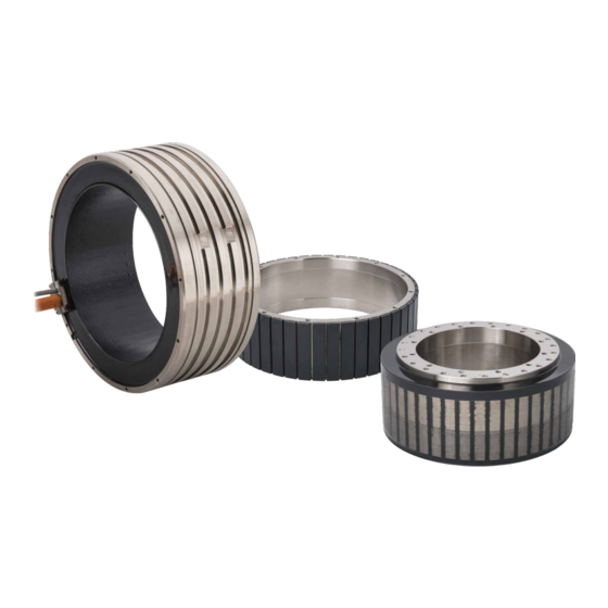
Torque Motor Installation Manual Basic Structure of Motor 2.1 General view HIWIN torque motor can get its best performance through water cooling. Bearing, position feedback Figure device and other related parts are excluded from shipment. Basic structure of motor is shown in ... -
Page 24: Product Code
: Ø 310mm : Ø 385mm : Ø 485mm : Ø 565mm Rotor (Magnet) height: :30mm :50mm :70mm :100mm :150mm Winding code: :Standard :Low Back emf Optional: :Standard :Customized Reserved: :Standard XX :Characteristics Code See motor datasheet HIWIN MIKROSYSTEM Corp. -
Page 25: Tm-2/Im-2 Series Codification
:90° output in tangent direction with cable clamp (temp. cable straight output) :All cable separate with cable clamp (straight output) ⋮ Reserved: :Standard(without bridge) :Bridge on cable side ⋮ 1). Cable output style schematics refer to Figure 2.2 HIWIN MIKROSYSTEM Corp. - Page 26 (temp. cable straight output) Note: :All cable separate with cable clamp (straight output) The style shown above is schematic diagram, and the shape may be modified in case of design purpose. Figure 2.2 Cable output style HIWIN MIKROSYSTEM Corp.
-
Page 27: Logistics Content
And have one magnetic warning sign on the rotor. Here is an example of these labels: Name label Simple label Stator mark Rotor label ⑤ ①:Motor type ②:Serial number ③:Article number ④:Drawing number ⑤:Laser engraving trademark Magnetic warning sign HIWIN MIKROSYSTEM Corp. - Page 28 Torque Motor Installation Manual Configuration 3. Configuration Configuration ........................3-1 Torque motor selection .................... 3-2 Thermal calculation ....................3-6 3.2.1 Heat loss ...................... 3-6 3.2.2 Continuous operating temperature ............... 3-7 Thermal time constant ..................... 3-7 Power supply and controller selection ..............3-9 Water cooling system calculation ................
-
Page 29: Configuration
Calculate equivalent torque Motor sizing and T-N curve confirmation Select the appropriate motor from HIWIN’s catalogue in accordance with calculated maximum torque, equivalent torque and speed. Ensure the speed and the corresponding torque under all operating conditions are within the range of torque-speed curve of the motor. - Page 30 Where �� is angular velocity, �� is angular acceleration, �� is moving time and φ is angular displacement. Users can choose two of the four parameters (��, ��, �� and φ ) as designed parameters. The left two parameters can be calculated by above equations. ※ Motion velocity profile HIWIN MIKROSYSTEM Corp.
- Page 31 �� second can be calculated as below. (�� +�� ×�� +�� ×�� +(�� −�� ×�� = √ �� �� �� �� �� �� �� �� +�� +�� +�� ��(������/��) �� ������ ��(������) �� �� �� �� HIWIN MIKROSYSTEM Corp.
- Page 32 STEP 3 Motor sizing and T-N curve confirmation With the help of HIWIN’s motor specification, users can select the appropriate motor from peak torque and equivalent torque, and ensure speed and torque under all operating conditions is within the range of the motor’s T-N curve.
-
Page 33: Thermal Calculation
Since rotational speed is directly proportional to frequency, iron loss will be larger at high speed. However, rotational speed for HIWIN torque motor is low, so iron loss is relatively less than copper loss. Rotational speed value indicated by HIWIN drawing and specification is the maximum peak speed that the motor can reach. -
Page 34: Continuous Operating Temperature
TMRW series is available to either water cooling or air cooling while TM-2 and IM-2 series are mainly available to water cooling. Ensure parameters you use fit the specification, and keep coil temperature from exceeding 120℃. (for □M-2 is 130℃). Please contact HIWIN for other applications. 3.2.2 Continuous operating temperature Steady state temperature of motor coil is determined by the proportion of copper loss and iron loss. - Page 35 ) = coil temperature to be cooled [℃](after power off time �� �� �� �� = power off time [������] �� The time allocation of load cycle during motor operation can be determined by the two formulas above HIWIN MIKROSYSTEM Corp.
-
Page 36: Power Supply And Controller Selection
This phenomenon will be more obvious when the motor cable is longer. If the length of the cable between the controller and the motor is longer than 10 m, it HIWIN MIKROSYSTEM Corp. -
Page 37: Water Cooling System Calculation
���� 3.5 Water cooling system calculation The features of motor indicated in HIWIN torque motor drawing and specification are suitable for water cooling condition, and coolant temperature is 20℃. Taking oil as coolant is also acceptable. Just properly modify the performance of motor based on the features of coolant. The cooling condition indicated in specification: coil temperature should be less than 120℃(130℃... - Page 38 Torque (��) �� �� Power loss (��) 8262 1787 Temperature difference ℃ ℃ ∆�� between inlet and outlet ( ��/������ ��/������ Coolant flow (��) 4.27 Pressure difference ������ ������ 0.54 ∆�� between inlet and outlet ( HIWIN MIKROSYSTEM Corp. 3-11...
-
Page 39: Coolant Selection
Configuration 3.6 Coolant selection Coolant needs to be prepared by the user. Anti-corrosion coolant needs to be used for HIWIN torque motor. The design and performance test of HIWIN torque motors are based on pure water. If customers use oil as the coolant, the heat that can be taken away by the same flow rate will be reduced and so will the motor power, otherwise the flow rate should be increased to keep the motor power. -
Page 40: Water Coolant Diagram
MW99UE01-2104 Torque Motor Installation Manual Configuration 3.7 Water coolant diagram Flow Flow control Pump Thermometer Indicator (Adjustable) This section shows simple schematic water cooling diagram: a. Single torque motor b. Parallel operation HIWIN MIKROSYSTEM Corp. 3-13... - Page 41 MW99UE01-2104 Torque Motor Installation Manual Configuration c. Share with other device(s) In any case, sharing flow with other device should be monitor flow and control it. d. Serial Circuit Never do serial circuit! 3-14 HIWIN MIKROSYSTEM Corp.
-
Page 42: Motor Interface Design
Torque Motor Installation Manual Motor Interface Design 4. Motor Interface Design Motor Interface Design ....................... 4-1 Water cooling design ....................4-2 4.1.1 Water cooling channel position ..............4-3 4.1.2 Water cooling channel dimension ..............4-4 4.1.3 Water cooling channel configuration ............. 4-6 4.1.4 O-ring features ..................... -
Page 43: Water Cooling Design
4.1 Water cooling design HIWIN torque motor can be cooled by water or air. (TM-2 and IM-2 are only available with water-cool) Water cooling channel is designed on the outer case of stator. O-ring is installed outside the water cooling channels as a leak-proof device. -
Page 44: Water Cooling Channel Position
L (����) □M-2-13 □M-2-15 □M-2-17 □M-2-1A □M-2-1F □M-2-43 □M-2-45 □M-2-47 □M-2-4A □M-2-4F □M-2-23 □M-2-25 □M-2-27 □M-2-2A □M-2-2F □M-2-73 □M-2-75 □M-2-77 □M-2-7A □M-2-7F □M-2-A3 □M-2-A5 □M-2-A7 □M-2-AA □M-2-AF □M-2-D3 □M-2-D5 □M-2-D7 □M-2-DA □M-2-DF □M-2-G3 □M-2-G5 □M-2-G7 □M-2-GA □M-2-GF HIWIN MIKROSYSTEM Corp. -
Page 45: Water Cooling Channel Dimension
TMRW7F(L) Note: The water cooling inlet and outlet mentioned above must have the smallest inner diameter to ensure the minimum water flow given in the datasheet. The maximum pressure that HIWIN torque motors can withstand is 10 ������. HIWIN MIKROSYSTEM Corp. - Page 46 □M-2-7F Note: The water cooling inlet and outlet mentioned above must have the smallest inner diameter to ensure the minimum water flow given in the datasheet. The maximum pressure that HIWIN torque motors can withstand is 10 ������. HIWIN MIKROSYSTEM Corp.
-
Page 47: Water Cooling Channel Configuration
No matter motor cable outlet is facing upward or downward, coolant outlet should be above and coolant inlet should be below. (Defined by the direction of gravity.) Besides, coolant inlet and outlet must be aligned with motor cable outlet (refer to HIWIN approved drawing for motor cable outlet position). -
Page 48: O-Ring Features
VITON 70° The quality of O-rings shipped by HIWIN is defined in accordance with ISO3601 standards (Series G & Grade N); different brands of Fluor elastomers have different product names, also known as FKM and FPM. It is Viton® with DuPont™ from the United States, Dyneon™ with 3M from the United States, and DAI-EL with Daikin®... -
Page 49: Fixture Dimension
4.1.5 Fixture dimension Fixture dimension for each series is given as below. (The default setting for the shipment of TM-2/IM-2 is to ship the stator and rotor separately. Please contact HIWIN, if shipment with complete assembled motor is required.) TMRW1 Series... - Page 50 Torque Motor Installation Manual Motor Interface Design TMRWD Series TMRWG Series Figure 4.5 Fixture diagram Table 4.6 Fixture dimension Fixture maximum length: �� Fixture thickness: �� Motor type (����) (����) TMRW1□ TMRW2□ TMRW4□ TMRW7□ TMRWA□ TMRWD□ TMRWG□ HIWIN MIKROSYSTEM Corp.
-
Page 51: Rotor Interface Design
Table 4.7 mounting interface suggestion (TMRW/TM-2) Flatness A Flatness B ∅�� ∅�� Type (����) (����) (����) (����) TMRW1□/TM-2-1□ 84.5 76.5 0.05 0.05 TMRW2□/TM-2-2□ 110/108.4 0.05 0.05 TMRW4□/TM-2-4□ 158.5 TMRW7□/TM-2-7□ 222.5/218.8 TMRWA□/TM-2-A□ 284.5 TMRWD□/TM-2-D□ 0.15 0.15 TMRWG□/TM-2-G□ 0.15 0.15 4-10 HIWIN MIKROSYSTEM Corp. - Page 52 Torque Motor Installation Manual Motor Interface Design ∅�� ������. Shaft ���� Min. 1 Rotor Type A ∅�� Rotor Shaft Type B Rotor ���� Min. 1 Shaft ∅�� ������. Type C Figure 4.7 Rotor mounting interface (IM-2) HIWIN MIKROSYSTEM Corp. 4-11...
- Page 53 Motor Interface Design Table 4.8 mounting interface suggestion (IM-2) ∅�� Flatness A Flatness B (����) Type Type A Type B Type C (����) (����) IM-2-2□ 61.5 0.05 0.05 IM-2-4□ IM-2-7□ 164.5 IM-2-A□ 236.5 IM-2-G□ 0.15 0.15 4-12 HIWIN MIKROSYSTEM Corp.
-
Page 54: Stator Interface Design
Housing is suggested to be chamfered, deburred and rounded (the recommended dimension is shown in Figure 4.9 ) to avoid scratching O-ring and causing water leaking. Housing Stator Figure 4.8 Stator mounting interface Deburring and rounding Figure 4.9 Housing mounting interface HIWIN MIKROSYSTEM Corp. 4-13... -
Page 55: Air Gap And Assembly Concentricity
Air gap: δ Assembly concentricity: C Motor type (����) (����) TMRW1□ TMRW2□ TMRW4□ TMRW7□ TMRWA□ TMRWD□ TMRWG□ Table 4.10 TM-2 series air gap and assembly concentricity dimension Air gap: δ Assembly concentricity: C Type (����) (����) TM-2-1□ 0.25 TM-2-2□ 0.25 TM-2-4□ 0.35 TM-2-7□... - Page 56 Torque Motor Installation Manual Motor Interface Design Table 4.11 IM-2 series air gap and assembly concentricity dimension Air gap: δ Assembly concentricity: C Type (����) (����) IM-2-2□ 0.55 IM-2-4□ 0.45 IM-2-7□ 0.70 IM-2-A□ 0.65 IM-2-G□ 0.75 HIWIN MIKROSYSTEM Corp. 4-15...
-
Page 57: Force Between Stator And Rotor
5158 Radial force varies by length of iron core. �� ���������� = Radial force �� × �� stands for length of iron core. Length of iron core for each series is given as below Table 4.13. 4-16 HIWIN MIKROSYSTEM Corp. -
Page 58: Axial Force
Table 4.14 Maximum value of axial force Axial force: ��(��) Axial force: ��(��) Axial force: ��(��) Type Type Type TMRW1□ TM-2-1□ IM-2-2□ TMRW2□ TM-2-2□ IM-2-4□ TMRW4□ TM-2-4□ IM-2-7□ TMRW7□ TM-2-7□ IM-2-A□ TMRWA□ TM-2-A□ IM-2-G□ TMRWD□ TM-2-D□ TMRWG□ 1335 TM-2-G□ HIWIN MIKROSYSTEM Corp. 4-17... -
Page 59: Screw Tightening Torque
TM-2-4A TMRW4A(L) TM-2-4F TMRW4F(L) M5 x 0.8P x 10DP 7.85 TM-2-7A TMRW7A(L) TM-2-7F TMRW7F(L) TM-2-A3 TMRWA3(L) TM-2-A5 TMRWA5(L) M6 x 1P x 12DP 11.77 TM-2-A7 TMRWA7(L) TMRWAA(L) TM-2-AA M6 x 1P x 12DP 11.77 TM-2-AF TMRWAF(L) 4-18 HIWIN MIKROSYSTEM Corp. - Page 60 11.77 IM-2-7A Stator M5 x 0.8P x 10DP 7.85 IM-2-7F Rotor M6 x 1.0P x 12DP 11.77 IM-2-A3 IM-2-A5 Stator/Rotor M6 x 1P x 12DP 11.77 IM-2-A7 IM-2-AA Stator/Rotor M6 x 1P x 12DP 11.77 IM-2-AF HIWIN MIKROSYSTEM Corp. 4-19...
- Page 61 MW99UE01-2104 Torque Motor Installation Manual Motor Interface Design IM-2-G5 Stator/Rotor M8 x 1.25P x 12DP 24.52 IM-2-G7 IM-2-GA Stator/Rotor M8 x 1.25P x 12DP 24.52 IM-2-GF 4-20 HIWIN MIKROSYSTEM Corp.
-
Page 62: Direction Of Rotation
If the motor cable is connected according to Table 4.18. The rotor will rotate in clockwise direction (view towards the rotor side without cable outlet, Figure 4.13). Figure 4.13 Illustration of rotational direction of the rotor HIWIN MIKROSYSTEM Corp. 4-21... -
Page 63: Motor Cable
TMRW45L TMRW47L TMRW4A TMRW4F TMRW73 TMRW75 TMRW77 TMRW7A TMRW7F TMRWA3 TMRWA5 TM-2-13-SA TM-2-15-SA TM-2-17-SA TM-2-1A-SA TM-2-1F-SA TM-2-23-PB TM-2-25-PB TM-2-27-PB TM-2-2A-PB TM-2-2F-PB TM-2-4F-PA TM-2-73-PB TM-2-75-PB TM-2-77-PB TM-2-7A-PB TM-2-7F-PB TM-2-A3-PB TM-2-A5-PB IM-2-23-PB IM-2-25-PB IM-2-27-PB IM-2-2A-PB IM-2-2F-PB IM-2-73-SA IM-2-A3-PB 4-22 HIWIN MIKROSYSTEM Corp. -
Page 64: Temperature Sensor Cable Specification
Type are given in Table 4.19. The cross-sectional area of temperature sensor cable is 0.25 mm and the pin assignment of temperature sensor cable for each type is given from Figure 4.15 to Figure 4.17. Note : Temperature sensor cable contains isolation net. The isolation net must be grounded. HIWIN MIKROSYSTEM Corp. 4-23... - Page 65 Table 4.19 Temperature sensors used in each Type Type Temperature sensor Remarks Type A PTC120(130) + Pt1000 Type B PTC100 + PTC120(130) + Pt1000 Standard Type C PTC120(130) + 3x Pt1000 Figure 4.15 Type A Figure 4.16 Type B Figure 4.17 Type C 4-24 HIWIN MIKROSYSTEM Corp.
-
Page 66: Bending Radius Of Cable
R= 4 x D R= 5 x D R= 5 x D installation Min. bending R= 7.5 x D radius of moving R= 7.5 x D R= 10 x D R= 10 x D installation HIWIN MIKROSYSTEM Corp. 4-25... -
Page 67: Setting Of Parallel Operation
□M-2 Series Pay attention to the following points when driving multiple motors in parallel. To drive the motors in parallel, contact HIWIN Engineering Department. The motors performing parallel operation should be the same type. The phase sequence of back EMF for motors performing parallel operation should be the same. - Page 68 Torque Motor Installation Manual Motor Interface Design Outlet position Outlet position Home position mark Home position mark Figure 4.18 Relative position of home position mark and outlet position during parallel operation Figure 4.19 Type A (Design 1) HIWIN MIKROSYSTEM Corp. 4-27...
- Page 69 MW99UE01-2104 Torque Motor Installation Manual Motor Interface Design Figure 4.20 Type A (Design 2) 4-28 HIWIN MIKROSYSTEM Corp.
- Page 70 MW99UE01-2104 Torque Motor Installation Manual Motor Interface Design Figure 4.21 Type B (Design 1) Figure 4.22 Type B (Design 2) HIWIN MIKROSYSTEM Corp. 4-29...
- Page 71 MW99UE01-2104 Torque Motor Installation Manual Motor Interface Design Figure 4.23 Type C (Design 1) Figure 4.24 Type C (Design 2) 4-30 HIWIN MIKROSYSTEM Corp.
-
Page 72: Temperature Sensor
�� = -4.1830 x 10 = 1000 [Ω] [℃ �� = 3.9083 x 10 �� = temperature [℃] [℃ �� = -5.7750 x 10 [℃ Standard Minimum Maximum ℃ Temperature ( Figure 4.25 Relationship between resistance and temperature (Pt1000) HIWIN MIKROSYSTEM Corp. 4-31... -
Page 73: Temperature Monitoring And Motor Protection
PTC reacts very quickly to a rise in temperature and, in conjunction with additional protective mechanisms on the control side, ensures reliable motor protection against overload. The PTC elements located in every phase winding in HIWIN motors are wired in series; they connect via two wires. -
Page 74: Connection To The Drive Amplifier
HIWIN advises the use of additional protective algorithm on the control side. The calculation of max. operating time with currents above continuous current can be found in Chapter 3.3. - Page 75 MW99UE01-2104 Torque Motor Installation Manual Motor Interface Design (This page is intentionally left blank.) 4-34 HIWIN MIKROSYSTEM Corp.
-
Page 76: Thermal Protection Device
Torque Motor Installation Manual Thermal Protection Device 5. Thermal Protection Device Thermal Protection Device ....................5-1 Features ........................5-2 Wiring of temperature module ................. 5-3... -
Page 77: Features
Figure 5.1 Thermal protection device 5.1 Features THPD must be used with HIWIN torque motor. It converts three temperature sensor inputs of motor into one analog output and two digital outputs and sends them to controller. -
Page 78: Wiring Of Temperature Module
Torque Motor Installation Manual Thermal Protection Device 5.2 Wiring of temperature module If the temperature sensor of the motor is Pt1000, it must be used with THPD-1000-120. The wiring structure diagram is shown below. Figure 5.2 Pt1000 wiring diagram HIWIN MIKROSYSTEM Corp. - Page 79 MW99UE01-2104 Torque Motor Installation Manual Thermal Protection Device (This page is intentionally left blank.) HIWIN MIKROSYSTEM Corp.
-
Page 80: Motor Installation
Torque Motor Installation Manual Motor Installation 6. Motor Installation Motor Installation ....................... 6-1 Install stator and rotor together ................6-4 Install stator and rotor separately ................6-6... - Page 81 Keep the following tools at hand at any time to release body parts (hands, fingers, feet, etc.) clamped by magnetic force. Hammer made of non-magnetized solid material (about 3Kg) Two wedge blocks composed of non-magnetized materials (wedge-shaped sharp angle 10°~15°, minimum height 50mm). HIWIN MIKROSYSTEM Corp.
- Page 82 Do not bring watches or magnetisable data storage media into the vicinity (<300 mm) of the torque motor systems! ATTENTION! Damage of the torque motor system! The torque motor system may be damaged by mechanical loading. Do not pull the cable directly. No heavy load or sharp object on motor. HIWIN MIKROSYSTEM Corp.
-
Page 83: Install Stator And Rotor Together
They are installed with the fixture provided by torque motor, and the fixture position can be either the outlet side or the other side. Before placing an order, customers can consult with HIWIN sales or engineers about the definition of the fixture position. HIWIN will offer drawing for customers to confirm. - Page 84 Pay attention to rotor’s strong magnetic suction. To avoid danger, keep it away from magnetic conductors (e.g. iron objects). Note: Refer to HIWIN approved drawing for the position of motor cable outlet. 5. Fix rotor on shaft. At this time, screw tightening torque is 80 percent of the specification (refer to Section 4.6 for screw tightening torque).
-
Page 85: Install Stator And Rotor Separately
To avoid water leaking, O-ring cannot be damaged (refer to Chapter 4 for the design of housing). Note: Refer to HIWIN approved drawing for the position of motor cable outlet. 6. Install lower guide tool on shaft if it is necessary. - Page 86 9. Check the air gap and assembly concentricity refer to Section 4.4 10. Rotate rotating part. Ensure that it rotates smoothly and that no interference occurs. 11. Install the remaining parts, such as connector of coolant inlet / outlet, lower supporting bearing and encoder. HIWIN MIKROSYSTEM Corp.
- Page 87 MW99UE01-2104 Torque Motor Installation Manual Motor Installation (This page is intentionally left blank.) HIWIN MIKROSYSTEM Corp.
- Page 88 Torque Motor Installation Manual Maintenance and Troubleshooting 7. Maintenance and Troubleshooting Maintenance and Troubleshooting ..................7-1 Troubleshooting....................... 7-5 HIWIN Torque motor trouble shooting form ............. 7-7 7.2.1 Identification of Motor and machine .............. 7-7 7.2.2 Conditions ....................7-7 7.2.3 Failure situation .................... 7-7 7.2.4...
- Page 89 Keep the following tools at hand at any time to release body parts (hands, fingers, feet, etc.) clamped by magnetic force. Hammer made of non-magnetized solid material (about 3Kg) Two wedge blocks composed of non-magnetized materials (wedge-shaped sharp angle 10°~15°, minimum height 50mm). HIWIN MIKROSYSTEM Corp.
- Page 90 8. Regularly check the air gap between the stator and rotor of the motor to keep it clean and undamaged. HIWIN torque motor is a direct drive system, there will be no wear during operation, but even so, improper operation or incorrect use environment will still shorten the life of the motor or even damage it.
- Page 91 6. To test the insulation resistance of the three phases of the motor. It must meet the requirements of 1000V_DC 60 sec>100 MΩ@25℃. If the insulation resistance decreases gradually at the same temperature compared to the previous several measurements, the motor may have begun to age, so special attention should be paid. HIWIN MIKROSYSTEM Corp.
-
Page 92: Maintenance And Troubleshooting
Speed is too slow frequency<1 ���� Abnormal operation of Check cooling system. cooling system Abnormal temperature of motor Wrong controller setting Check controller setting. outer casing Wrong motor Check motor parameters setting. parameters setting Abnormal operation of Check installation. bearing HIWIN MIKROSYSTEM Corp. - Page 93 Remove air bubbles or increase flow rate the cooling circuit to remove air bubbles. Motor generate local high heat Incorrect position of (uneven) Check the inlet/outlet of cooling circuit to inlet and outlet of fit according to approved drawing. cooling circuit HIWIN MIKROSYSTEM Corp.
-
Page 94: Hiwin Torque Motor Trouble Shooting Form
In the event a breakdown or error occurs with the torque motor, this form has been designed to help the user to provide HIWIN with the most essential details so that the unit can be troubleshooted and repaired efficiently and effectively. Avoiding any possible and unnecessary downtime. -
Page 95: Nc Parameters
□ NC(Numerical Control) type: __________________________________________________ □ Other comments:___________________________________________________________ List all parameters regarding to the motor, or send the corresponding file to HIWIN (in case HIWIN supplied the parameter data sheet for the motor, please send HIWIN this parameter file) ____________________________________________________________________________ ____________________________________________________________________________ A. -
Page 96: Electrical Troubleshooting
Remark the visual marks on the following figures: Blisters (draw ○) Burn point (draw △) Scratch (draw ☰) Flange wrinkle (draw ~) Cables and connections inspection: Any damage on cables/cable glands/cable connectors: □ No / □ Yes HIWIN MIKROSYSTEM Corp. -
Page 97: Appendix
Is there any metal particles on the magnets: □ No / □ Yes, something like _______________ 7.2.7 Appendix Please share all information with HIWIN to get a better understanding of the problem (photos, NC records, damaged parts). List all the file and parts sent to HIWIN:... -
Page 98: Tolerances And Hypotheses Of Motor Specifications
Torque Motor Installation Manual Tolerances and Hypotheses of Motor Specifications 8. Tolerances and Hypotheses of Motor Specifications Tolerances and Hypotheses of Motor Specifications ............8-1 Tolerances ....................... 8-2 Hypothesis of heat transfer ..................8-2... -
Page 99: Tolerances
Hypothesis of air cooling condition: ambient temperature around stator/rotor: 20℃; Hypothesis of water cooling conditions: around the rotor: 20℃ ℃ ℃ ℃ on average of the number of water cooling system and the interface design from Table 4.1and Table 4.4. HIWIN MIKROSYSTEM Corp. -
Page 100: Decommissioning And Disposal
Torque Motor Installation Manual Decommissioning and disposal 9. Decommissioning and disposal Decommissioning and disposal ..................9-1 Decommissioning ....................9-3 Disposal ........................9-4 9.2.1 Disposal of rotors ..................9-4 9.2.2 Disposal of packaging .................. 9-5... - Page 101 Keep the following tools at hand at any time to release body parts (hands, fingers, feet, etc.) clamped by magnetic force. Hammer made of non-magnetized solid material (about 3Kg) Two wedge blocks composed of non-magnetized materials (wedge-shaped sharp angle 10°~15°, minimum height 50mm). HIWIN MIKROSYSTEM Corp.
-
Page 102: Decommissioning
7. Insert the spacer between the gaps of stator and rotor. 8. When there are fixation plates of stator and rotor or self-designed stator and rotor fixing jigs, use these plates/jigs to fix the stator and rotor. HIWIN MIKROSYSTEM Corp. -
Page 103: Disposal
11. Use the original packaging or a safe way to pack and store it correctly. Note: If replace a new torque motor, it is recommended to use a new O-ring; when the O-ring needs to be replaced, please refer to Chapter 4.1.4 to purchase an appropriate O-ring or purchase it from HIWIN. 9.2 Disposal Products need to be disposed according to the normal recycling process in accordance with laws and regulations. -
Page 104: Disposal Of Packaging
Gauss, otherwise it is recommended to continue the above process. 9.2.2 Disposal of packaging The packaging materials and packaging auxiliary materials used by HIWIN are no problematic materials. Except for wood materials, they can be recycled and reused. Wood materials should be burned. - Page 105 MW99UE01-2104 Torque Motor Installation Manual Decommissioning and disposal (This page is intentionally left blank.) HIWIN MIKROSYSTEM Corp.
- Page 106 Torque Motor Installation Manual Technical Terms Technical Terms Technical Terms ......................... 9-6...
- Page 107 25℃. The larger motor constant represents the lower power loss when the motor outputs at the specific torque. Number of poles: 2p 2p represents the number of poles of the rotor, where p is the number of poles pair. 10-2 HIWIN MIKROSYSTEM Corp.
- Page 108 1 second when the motor is operating in the normal condition and the input current phase is balanced. And then the motor needs to rest for at least 6 seconds after it reaches the normal temperature to supply peak current. (For more accurate time, please contact HIWIN) ( ���� ) Peak torque: ��...
- Page 109 �� the torque is greater than �� , the duty cycle must be reduced. When �� is reached, only 1 second ���� �� output is allowed to avoid overheating of the stator. 10-4 HIWIN MIKROSYSTEM Corp.
- Page 110 Minimum water flow is the minimum flow required for normal cooling under water cooling system with pure water. If the operating environment is different, water flow must be modified by calculation (refer to Section 3.6). HIWIN MIKROSYSTEM Corp. 10-5...
- Page 111 IM-2 series will be the maximum continuous rated power in the field-weakening operation. The schematic as shown as below, the red dot is the maximum continuous rated power in the field-weakening operation 10-6 HIWIN MIKROSYSTEM Corp.
Need help?
Do you have a question about the TM-2 Series and is the answer not in the manual?
Questions and answers