Table of Contents
Advertisement
Quick Links
Advertisement
Table of Contents

Related Manuals for Hiwin SSA


Summary of Contents for Hiwin SSA
- Page 1 Single-Axis Linear Motor Stage User Manual www.hiwinmikro.tw...
-
Page 2: Table Of Contents
Contents CONTENTS 4.5 U ......13 NPACKING AND INSTALLING 1. GENERAL INFORMATION 5. ASSEMBLY AND CONNECTION 1.1 A ........ 1 5.1 A ..15 BOUT THIS USER MANUAL SSEMBLING THE LINEAR MOTOR SYSTEM 1.2 D ... 1 5.2 A ....... 16 EPICTIONS USED IN THIS USER MANUAL SSEMBLING THE MOVED LOAD 1.3 M... -
Page 3: Contents
Lists are indicated by bullet points. Example: The linear motor systems must not be operated: Outdoors ● In potentially explosive atmospheres ● 1.2.3 Information Information is to describe general information and recommendations. Example: Please contact HIWIN for special requests. 1.2.4 Depiction of safety notices... - Page 4 MM06UE01-2002 Safety notices are always indicated using a signal word and sometimes also a symbol for the specific risk (See section 1.2.4). The following signal words and risk levels are used: DANGER! Imminent danger! Non-compliance with the safety notices will result in serious injury or death! WARNING! Potentially dangerous situation! Non-compliance with the safety notices runs the risk of serious injury or death!
-
Page 5: Manufacturers Details
This user manual is protected by copyright. Any reproduction, publication in whole or in part, modification or abridgement requires the written approval of HIWIN MIKROSYSTEM. 1.5 Product monitoring Please inform HIWIN MIKROSYSTEM, the manufacturer of the linear motor systems, of: Accidents ●... -
Page 6: Basic Safety Notices
● 2.2 Reasonably foreseeable misuse The linear motor systems must not be operated: Outdoors ● In potentially explosive atmospheres ● 2.3 Conversions and modifications Modifications of the linear motor systems are not permitted! Please contact HIWIN MIKROSYSTEM for special request. -
Page 7: Residual Risks
MM06UE01-2002 2.4 Residual risks Normal operation of the linear motor systems constitutes no residual risks. Warnings about risks that may arise during maintenance and repair work are provided in the relevant sections. 2.5 Personnel requirements Only authorized persons may carry out work on the linear motor systems! They must be familiar with the safety equipment and regulations before starting work (See Table 2.1). -
Page 8: Labels On Linear Motor System
MM06UE01-2002 Table 2.2 Personal protective equipment (continued) Operating phase Personal protective equipment When carrying out maintenance and repairs, the following personal protective equipment is required: Maintenance and repairs Safety shoes ● Protective helmet ● Protective gloves ● 2.6.2 Protective equipment on the linear motor system Linear motor systems are fitted with position dampers. -
Page 9: Description Of The Linear Motor System
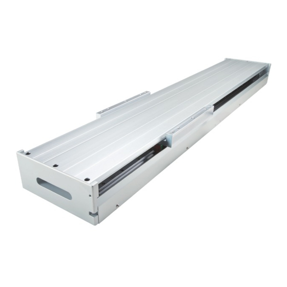
MM06UE01-2002 3. Description of the linear motor system 3.1 Field of application The linear motor system is used for traversing and (linear) movement of fixed mounted loads on the forcer housing. The model can be mounted and operated horizontally. 3.2 Main components of the linear motor system Fig. -
Page 10: Functional Description
MM06UE01-2002 3.3 Functional description Fig. 3.2 Principle of the linear motor system Table 3.2 Components and functionality Pos. Function Energy supply (standard version or customer-specific version) Positive (+) direction of motion. This is defined via the position of the reference switch. Motor cables, positioning measurement system, limit switches. - Page 11 MM06UE01-2002 3.3.3 Positioning measurement system ATTENTION! Damage caused by scratching! The measuring scale of the optical measuring system may be damaged by improper handling. Handle the measuring scale with care! ATTENTION! Damage to the magnetic positioning measurement system! Strong magnetic fields and vibrations can damage the magnetic positioning measurement system. Protect the magnetic positioning measurement system against strong magnetic fields! ...
-
Page 12: Transport And Installation
MM06UE01-2002 4. Transport and installation 4.1 Delivery 4.1.1 Delivery state The linear motor systems are supplied fully assembled, function tested and ready for connection. To prevent damage arising during transport, the linear motor systems are provided with transportation safety devices and shipping devices. - Page 13 MM06UE01-2002 ATTENTION! Damage of the linear motor system! The linear motor system may be damaged by mechanical loading. No heavy load on the cover! Only lift the linear motor system using the shipping devices provided (Fig. 4.2)! For longer linear motor system, provide additional protection of the center section. ...
-
Page 14: Requirements At The Installation Site
MM06UE01-2002 Fig. 4.2 lifting example – here for a LMSSA linear motor system(long stroke) 4.3 Requirements at the installation site 4.3.1 Ambient conditions Table 4.1 Ambient condition requirement Area of use For indoor use only Temperature 0 °C to 50 °C Humidity <... -
Page 15: Unpacking And Installing
MM06UE01-2002 When storing the linear motor system, attach signs warning of magnetic fields. 4.5 Unpacking and installing ATTENTION! Damage of attachments! Attachments may be damaged by mechanical loading. Secure and manoeuvre the linear motor system using the suspension points provided! ... -
Page 16: Assembly And Connection
MM06UE01-2002 5. Assembly and connection DANGER! Danger from electrical voltage! Before and during assembly, disassembly and repair work, dangerous currents may flow. Work may only be carried out by a qualified electrician and with the power supply disconnected! Before carrying out work on the linear motor system, disconnect the power supply and protect it ... -
Page 17: Assembling The Linear Motor System
MM06UE01-2002 5.1 Assembling the linear motor system Secure the screws with retaining rings to prevent them from accidentally coming loose! Steps to assemble the linear motor system: Remove the shipping devices. Remove the transportation safety device from the forcer housing. ... -
Page 18: Assembling The Moved Load
MM06UE01-2002 5.2 Assembling the moved load Steps to assemble the moved load: Clean the mounting surface on the linear motor system that is to receive the load. Clean the mounting surface of the load. Position the load over the corresponding mounting holes on the mounting surface (see Technical Information ... - Page 19 MM06UE01-2002 Fig. 5.2 Electrical connection for drive type of D1 Fig. 5.3 Electrical connection for drive type of D1-N 5.3.1 Connecting iron-core motors The temperature sensor system cable is routed as standard through the motor’s extension cable. Both cables are therefore connected to the motor plug.
- Page 20 MM06UE01-2002 ATTENTION! Danger of EMC interference in the encoder signal! Approved ESD precautions must be followed at all times during readhead and interface electrical connections. Make sure that the encoder cable has been shielded correctly! Ensure that the shielding is in full contact across the connectors! ...
-
Page 21: Commissioning
MM06UE01-2002 6. Commissioning 6.1 Switch on the linear motor system DANGER! Danger from strong magnetic fields! Strong magnetic fields around linear motor system pose a health risk to persons with implants (e.g. cardiac pacemakers) that are affected by magnetic fields. Persons with implants that are affected by magnetic fields should maintain a safe distance of at ... -
Page 22: Programming
MM06UE01-2002 Connect positioning measurement system cable (see Section 5.3.2). Switch on the controller. Check the positioning measurement system (see separate assembly instructions for the drive and positioning measurement system). Switch off the controller. Connect the motor cable (see Sections 5.3.1). ... -
Page 23: Maintenance And Cleaning
MM06UE01-2002 7. Maintenance and cleaning DANGER! Danger from electrical voltage! Before and during maintenance and cleaning, dangerous currents may flow. Work may only be carried out by a qualified electrician and with the power supply disconnected! Before carrying out work on the linear motor system, disconnect the power supply and protect it ... - Page 24 MM06UE01-2002 Remove the cover or bellows before maintenance: As for the cover, loose the screws on the cover. As for the bellows, detach the bellows form the forcer housing. Remove the cover/bellows carefully. Fig. 7.1 Exploded view of the cover – here for an LMSSA linear motor system During maintenance: Secure the linear motor system against being switched on without authorization.
-
Page 25: Linear Motor
MM06UE01-2002 7.1 Linear motor Ensure that no parts are located between the forcer and the magnet track! The linear motor operates maintenance-free. 7.2 Positioning measurement system 7.2.1 Magnetic positioning measurement system Ensure that no dirt particles are located between the encoder and the measuring scale! The magnetic positioning measurement system works on a non-contact basis and thus requires no maintenance. - Page 26 ) are used! Further information about lubrication and selection of approved lubricants can be found in the user manual for linear guideways at www.hiwin.tw. Fig. 7.3 Grease nipples on linear guideways Relubricating interval every 200–600 operating hours or 1000 km.
-
Page 27: Troubleshooting
Drive amplifier motor commutation Adapt commutation parameters of the drive does not function properly amplifier Operating noise from the Relubrication required otherwise Lubrication or consultation with HIWIN forcer risk of bearing damage MIKROSYSTEM The axis generates cracking EMC interference in the encoder... -
Page 28: Disposal
MM06UE01-2002 Table 8.1 Fault table (continued) Fault Possible cause Remedy The forcer jerks while EMC interference in the encoder Place motor cable and/or encoder cable moving and generates signal, encoder cable plug shield in full contact with the earthing operating noise that is not connection defective, pin bent in terminal of the amplifier, check pin in plug caused by the profile... -
Page 29: Declaration Of Incorporation
MM06UE01-2002 10. Declaration of Incorporation...
Need help?
Do you have a question about the SSA and is the answer not in the manual?
Questions and answers