
Related Manuals for Hiwin EM1 Series


Summary of Contents for Hiwin EM1 Series
- Page 1 MC03UE01-2305_V1.1 User Manual EM1 Series AC Servo Motors EM1-01-1-EN-2307-MA www.hiwin.de...
- Page 2 Complete or partial reproduction is not permitted without our permission. These assembly instructions are protected by copyright. Any reproduction, publication in whole or in part, modification or abridgement requires the written approval of HIWIN GmbH. EM1 Series AC Servo Motors...
-
Page 3: Table Of Contents
............EM1 Series AC Servo Motors... -
Page 4: About This Manual
AC servo motor must only be used for the intended purpose as described. Any other use of the AC servo motor shall be considered as improper usage. HIWIN is not responsible for any product damage or personal injury caused by this. - Page 5 User Manual About this Manual HIWIN offers 1-year warranty for the product. The warranty does not cover damage caused by improper usage (refer to the precautions and instructions stated in this manual) or natural disaster. Protective requirement Table 1.1:...
- Page 6 20 − 80 Rate of change of temperature (°C/min) Air pressure 70 − 106 Condensation Not allowed Formation of ice Not allowed Store the motor in an environment with good protection. (indoor/factory) EM1 Series AC Servo Motors EM1-01-1-EN-2307-MA Page 6 of 80...
- Page 7 Maintenance precautions Warning! Risk of personal injury or damage to property. Do not disassemble or modify the product. If the product malfunctions, do not repair the product by yourselves, please contact HIWIN for repairs. Disposal precautions ...
-
Page 8: Safety Instruction
Mandatory Signs Wear head protection! Refer to user manual! Disconnect before Wear protective gloves! carrying out maintenance or repair. Wear safety footwear! Lifting point. Connect an earth terminal to the ground! EM1 Series AC Servo Motors EM1-01-1-EN-2307-MA Page 8 of 80... - Page 9 Do not use the product in an environment where it may be shocked. Do not directly strike the shaft or encoder, as hitting or pounding. HIWIN is not responsible for any damage, accident or injury caused by this. Do not pick up or place the motor only by pulling its cable or shaft.
-
Page 10: Copyright
This user manual is protected by copyright. Any reproduction, publication in whole or in part, modification or abridgement requires the written approval of HIWIN. Note HIWIN reserves the right to change the contents of this manual or product specifications without prior notice. Manufacturer information... -
Page 11: Basic Safety Information
AC servo motors must not be operated: Outdoors. In potentially explosive atmospheres. Conversions and modifications Warning! Risk of personal injury or damage to property. Conversions or modifications to AC servo motor are prohibited. EM1 Series AC Servo Motors EM1-01-1-EN-2307-MA Page 11 of 80... -
Page 12: Residual Risks
User Manual Basic safety information Modifications of AC servo motor are not permitted. Please contact HIWIN for special request. Residual risks Caution! Personal injury or damage to property. During normal operation, there are no residual risks associated with AC servo motor ... -
Page 13: Labels On Servo Motor
Product name Serial No. Motor type Company address Part No. CE mark Input spec. UL mark Output spec. QR mark Location of Safety Symbols on Motor Name plate Anti-knocking High EM1 Series AC Servo Motors EM1-01-1-EN-2307-MA Page 13 of 80... -
Page 14: Product Description
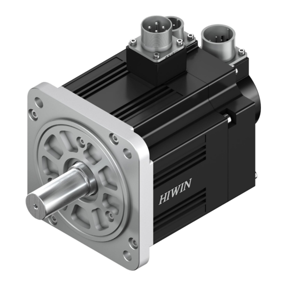
50 W – 750 W AC servo motor appearance are as bellowing. Encoder connector Front cover Encoder cable Oil seal Power cab Shaft (rotor) Encoder cab Encoder cover (encoder) Power cable Brake cover (brake) Power connector Motor cover (stator) EM1 Series AC Servo Motors EM1-01-1-EN-2307-MA Page 14 of 80... -
Page 15: Main Components Of Servo Motor
Encoder connector Oil seal Encoder cover (encoder) Shaft (rotor) Brake cover (brake) Back cover Main components of servo motor Combination of HIWIN AC servo motors and servo drives. Servo Motor Model Rated Output Rated Torque Rated Speed Servo Drive Model EM1-C-M-05-2-⎕-⎕-0-⎕... -
Page 16: Order Code
Standard Customized Shaft type: Round shaft / without oil seal Round shaft / with oil seal Shaft with key / without oil seal Shaft with key / with oil seal EM1 Series AC Servo Motors EM1-01-1-EN-2307-MA Page 16 of 80... - Page 17 1, 2, 3 Mode name Type: Standard Fieldbus Control Interface: Voltage command and pulse EtherCAT (CoE) mega-ulink (with HIWIN MoE HIMC motion controller or API/MPI motion control command library) MECHATROLINK-III PROFINET Special Function: Gantry No special function 7, 8 Rated output:...
- Page 18 Cable length can be customized for integer number, for example (1 m, 2 m, 3 m…30 m) Pin assignment and connector specification can be referred to chapter 5.2.1. Bending radius limitation of power cable can be referred to chapter 5.2.1.4. EM1 Series AC Servo Motors EM1-01-1-EN-2307-MA Page 18 of 80...
- Page 19 Cable length can be customized for integer number, for example (1 m, 2 m, 3 m…30 m) Pin assignment and connector specification can be referred to chapter 5.2.1. Bending radius limitation of power cable can be referred to chapter 5.2.1.4. EM1 Series AC Servo Motors EM1-01-1-EN-2307-MA Page 19 of 80...
- Page 20 EM1AM1K20F0⎕ HVPM04⎕B⎕⎕MB HVE23A⎕B⎕⎕MB EM1AM1K2BF0⎕ HVPM06⎕B⎕⎕MB EM1DM1A20E0⎕ 1.2 kW HVPM04⎕B⎕⎕MB HVE23I⎕B⎕⎕MB ED1⎕-⎕⎕-2032-A⎕ EM1DM1A2BE0⎕ HVPM06⎕B⎕⎕MB EM1DM1A20F0⎕ HVPM04⎕B⎕⎕MB HVE23A⎕B⎕⎕MB EM1DM1A2BF0⎕ HVPM06⎕B⎕⎕MB EM1DM2K20E0⎕ 2 kW HVPM04⎕B⎕⎕MB HVE23I⎕B⎕⎕MB EM1DM2K2BE0⎕ HVPM06⎕B⎕⎕MB EM1DM2K20F0⎕ HVPM04⎕B⎕⎕MB HVE23A⎕B⎕⎕MB EM1DM2K2BF0⎕ HVPM06⎕B⎕⎕MB EM1 Series AC Servo Motors EM1-01-1-EN-2307-MA Page 20 of 80...
- Page 21 DC 24±10 % Braking time Release time 6000, 0.62 0, 0.62 S1 (3-Phase) S3 (3-Phase) S1(1-Phase) S3(1-Phase) 0, 0.159 3000, 0.159 6000, 0.0795 1000 2000 3000 4000 5000 6000 Speed(rpm) EM1 Series AC Servo Motors EM1-01-1-EN-2307-MA Page 21 of 80...
- Page 22 Brake input voltage DC 24±10 % Braking time Release time 4600, 1.197 S1 (3-Phase) 6000, 0.874 S3 (3-Phase) S1(1-Phase) S3(1-Phase) 3000, 0.318 6000, 0.159 1000 2000 3000 4000 5000 6000 Speed(rpm) EM1 Series AC Servo Motors EM1-01-1-EN-2307-MA Page 22 of 80...
- Page 23 5000, 2.24 0, 2.24 S1 (3-Phase) 6000, 1.87 S3 (3-Phase) 6000, 1.76 S1 (1-Phase) S3 (1-Phase) 0, 0.64 3000, 0.64 6000, 0.32 1000 2000 3000 4000 5000 6000 7000 Speed (rpm) EM1 Series AC Servo Motors EM1-01-1-EN-2307-MA Page 23 of 80...
- Page 24 0, 4.44 S1 (3-Phase) 5000, 3.51 S3 (3-Phase) 6000, 2.92 S1 (1-Phase) S3 (1-Phase) 6000, 2.27 0, 1.27 3000, 1.27 6000, 0.638 1000 2000 3000 4000 5000 6000 Speed (rpm) EM1 Series AC Servo Motors EM1-01-1-EN-2307-MA Page 24 of 80...
- Page 25 4267, 8.36 0, 8.36 S1 (3-Phase) S3 (3-Phase) S1 (1-Phase) 6000, 5.43 6000, 5.2 S3 (1-Phase) 0, 2.39 3000, 2.39 6000, 1.2 1000 2000 3000 4000 5000 6000 7000 Speed (rpm) EM1 Series AC Servo Motors EM1-01-1-EN-2307-MA Page 25 of 80...
- Page 26 2000, 14.3 0, 14.3 S3 (3-Phase) S1 (1-Phase) S3 (1-Phase) 1925, 11.59 0, 4.77 2000, 4.77 3000, 5 3000, 2.77 3000, 2.385 1000 1500 2000 2500 3000 3500 Speed (rpm) EM1 Series AC Servo Motors EM1-01-1-EN-2307-MA Page 26 of 80...
- Page 27 S1 (3-Phase) Technical Data 2500, 16 S3 (3-Phase) S1 (1-Phase) 2500, 14.7 S3 (1-Phase) 5000, 8.3 2000, 5.7 5000, 6.4 4500, 2.5 1000 2000 3000 4000 5000 6000 Speed (rpm) EM1 Series AC Servo Motors EM1-01-1-EN-2307-MA Page 27 of 80...
- Page 28 0, 30 2500, 30 S3 (3-Phase) S1 (1-Phase) 2000, 23 S3 (1-Phase) 5000, 15 0, 9.55 2000, 9.55 4500, 5 4500, 2.5 1000 2000 3000 4000 5000 6000 Speed (rpm) EM1 Series AC Servo Motors EM1-01-1-EN-2307-MA Page 28 of 80...
- Page 29 * indicates motor shaft and connector are not included.(If the motor shaft needs IP protection, oil seal is necessary). The nominal motor properties are all single-phase/three-phase 220V input power. Please contact the sales representatives of HIWIN if you need 110V motor properties. 3.3.3 Mechanical overview EM1-C-M-05-2-X-X-0-X ...
- Page 30 User Manual Product description EM1-C-M-40-2-X-X-0-X EM1-C-M-75-2-X-X-0-X EM1-A-M-1K-2-X-X-0-X EM1-D-M-1A-2-X-X-0-X EM1 Series AC Servo Motors EM1-01-1-EN-2307-MA Page 30 of 80...
- Page 31 Acceleration torque (Nm) Deceleration torque (Nm) There are many types of mechanical transmission, here we list three types of common transmission mechanism and requirements for motor sizing, as the table below: EM1 Series AC Servo Motors EM1-01-1-EN-2307-MA Page 31 of 80...
- Page 32 Work pieces weight / quantities Distance from work pieces to rotation axis 3.3.4.2 Motion Profile Trapezoidal profile Triangle profile Legend table „Motion Profile“ Acceleration time Deceleration time EM1 Series AC Servo Motors EM1-01-1-EN-2307-MA Page 32 of 80...
- Page 33 Motor speed calculation × 60 V ∶ velocity ( Ball Screw × 60 V ∶ velocity ( πD Pulley & Belt ���� × 30 ���� ∶ angular velocity ( π Rotary Table EM1 Series AC Servo Motors EM1-01-1-EN-2307-MA Page 33 of 80...
- Page 34 ) − T Deceleration torque × t × t × t = � Equivalent torque tc = ta + tf + td + ts ts ∶ stop time (sec) EM1 Series AC Servo Motors EM1-01-1-EN-2307-MA Page 34 of 80...
- Page 35 − ( ���� + ���� + ���� ) + ���� Step 6: Calculate energy (capacity) consumed by the regenerative resistor (PR). ���� ���� ���� ���� ���� ���� ���� ���� ���� EM1 Series AC Servo Motors EM1-01-1-EN-2307-MA Page 35 of 80...
- Page 36 Warning! Personal Injury or Damage to Property. The environment temperature will rise due to the motor operating. AC servo motor grounding terminal must be installed properly. EM1 Series AC Servo Motors EM1-01-1-EN-2307-MA Page 36 of 80...
- Page 37 250 (L) * 250 (W) * 6 (T) mm EM1-C-M-40 Aluminum Alloys EM1-C-M-75 EM1-A-M-1K 300 (L) * 300 (W) * 6 (T) mm EM1-D-M-1A Aluminum Alloys EM1-D-M-2K Abb. 3.1: EM1-C-M-05 (50 W) Abb. 3.2: EM1-C-M-10 (100 W) EM1 Series AC Servo Motors EM1-01-1-EN-2307-MA Page 37 of 80...
- Page 38 User Manual Product description Abb. 3.3: EM1-C-M-20 (200 W) Abb. 3.4: EM1-C-M-40 (400 W) Abb. 3.5: EM1-C-M-75 (750 W) EM1 Series AC Servo Motors EM1-01-1-EN-2307-MA Page 38 of 80...
- Page 39 User Manual Product description Abb. 3.6: EM1-A-M-1K (1 KW) Abb. 3.7: EM1-D-M-1A (1,2 KW) Abb. 3.8: EM1-D-M-2K (2 KW) EM1 Series AC Servo Motors EM1-01-1-EN-2307-MA Page 39 of 80...
-
Page 40: Transport And Setup
Delivery the motor in an environment with good protection. (indoor/factory) Note Avoid exposing to direct sunlight. Keep away from electric magnetic interference source sites such as welding and discharge machines. EM1 Series AC Servo Motors EM1-01-1-EN-2307-MA Page 40 of 80... -
Page 41: Transport To The Installation Site
Plant power grounding line conforms to international requirements Note Avoid exposing to direct sunlight. Keep away from electric magnetic interference source sites such as welding and discharge machines. EM1 Series AC Servo Motors EM1-01-1-EN-2307-MA Page 41 of 80... -
Page 42: Storage
Step 5: Ensure the appearance and nameplate on AC servo motor are the same with the catalogue. Step 6: Dispose of packaging in an environmentally friendly way. EM1 Series AC Servo Motors EM1-01-1-EN-2307-MA Page 42 of 80... -
Page 43: Assembly And Connection
When in the vicinity of the AC servo motor systems, the following personal protective equipment is required: Safety shoes Protective helmet Protective gloves 5.1.3 Servo motor installation 5.1.3.1 Motor Orientation Horizontal: cable lead must face downward to prevent oil or water penetration. EM1 Series AC Servo Motors EM1-01-1-EN-2307-MA Page 43 of 80... - Page 44 1 Nm = 10,1972 kgf⋅cm Protective Structure HIWIN servo motor protective structure is described below. 50 W to 750 W: IP65 Except for power connector, encoder connector, motor through shaft section need to add oil seal which is optional for all type of AC servo motor.
- Page 45 Check whether the connection is firm and accurate before carrying out any further steps. After having assembled the motor mechanically, prepare it for electrical connection. (See section 5.2 Electrical installation) EM1 Series AC Servo Motors EM1-01-1-EN-2307-MA Page 45 of 80...
- Page 46 Lean shaft on a solid surface. Make sure key be pressed vertically. Press velocity should under 400 mm/min. Punching is prohibited. Press vertically force < 10 Lean on a solid EM1 Series AC Servo Motors EM1-01-1-EN-2307-MA Page 46 of 80...
- Page 47 Caution! Risk of Personal Injury or Damage to Property. Be sure that key be pressed vertically. Be careful with the sharp keyway when cleaning or installing key. EM1 Series AC Servo Motors EM1-01-1-EN-2307-MA Page 47 of 80...
- Page 48 (Allowable radial force): Frame size Allowable radial force(X) [Force unit: Newton] / [X unit: mm] x=10 x=15 x=20 x=25 x=30 x=35 x=40 x=45 x=50 40 mm 60 mm 80 mm 130 mm EM1 Series AC Servo Motors EM1-01-1-EN-2307-MA Page 48 of 80...
- Page 49 Conduct installation only when the main power is shut OFF. When installing the motor, pay attention to the following three types of basic deviation. Illustrations are shown below. Declination (B): Axial direction displacement (C): Eccentricity (A): EM1 Series AC Servo Motors EM1-01-1-EN-2307-MA Page 49 of 80...
- Page 50 So make sure that the deviation between the two axes is within the coupling’s allowable deviation. When choosing a coupling, we recommend choosing a flexible coupling that can absorb the eccentricity, declination and axial direction displacement. EM1 Series AC Servo Motors EM1-01-1-EN-2307-MA Page 50 of 80...
-
Page 51: Electrical Installation
Black European terminal 18 AWG 2,8 mm Green Green R type terminal 18 AWG 2,8 mm Yellow European terminal 18 AWG 2,8 mm Blue European terminal 18 AWG 2,8 mm EM1 Series AC Servo Motors EM1-01-1-EN-2307-MA Page 51 of 80... - Page 52 3,6 mm Black European terminal 14 AWG 3,6 mm Green R type terminal 14 AWG 3,6 mm White European terminal 20 AWG 1,8 mm Black European terminal 20 AWG 1,8 mm EM1 Series AC Servo Motors EM1-01-1-EN-2307-MA Page 52 of 80...
- Page 53 24 AWG 1,3 mm Blue (Black) 24 AWG 1,3 mm Serial Data Signal Yellow (Red) 24 AWG 1,3 mm Yellow (Black) 24 AWG 1,3 mm Shielding Shielding Black Houing Shielding EM1 Series AC Servo Motors EM1-01-1-EN-2307-MA Page 53 of 80...
- Page 54 24 AWG 1,3 mm Green (Black) Black 24 AWG 1,3 mm Serial Data Yellow (Red) 24 AWG 1,3 mm Signal Yellow (Black) 24 AWG 1,3 mm Shielding Shielding Black Housing Shielding EM1 Series AC Servo Motors EM1-01-1-EN-2307-MA Page 54 of 80...
- Page 55 24 AWG 1,3 mm Green (Black) Black 24 AWG 1,3 mm Serial Data Yellow (Red) 24 AWG 1,3 mm Signal Yellow (Black) 24 AWG 1,3 mm Shielding Shielding Black Housing Shielding EM1 Series AC Servo Motors EM1-01-1-EN-2307-MA Page 55 of 80...
- Page 56 (10H × A + 0,0014H × B + 2H × C) × 2 × 313 + 24H × C × 52 = 298(mAh) 1440mAh Battery life = = 4,8(year) 298mAh EM1 Series AC Servo Motors EM1-01-1-EN-2307-MA Page 56 of 80...
- Page 57 Encoder cable (50 W – 2 KW) 5.2.2 Electrical Connection Before connecting, you must use HIWIN power cables and encoder cables. Our cables provide a number of advantages, such as UL/CSA authorization, extreme load capability and resistance as well as a design suitable for EMC.
- Page 58 voltage of the drive is 400 V; Less than 50 Ω when it is 220 V and shall be less than 100 Ω when it is 110 V. EM1 Series AC Servo Motors EM1-01-1-EN-2307-MA Page 58 of 80...
-
Page 59: Commissioning
The flow chart for tuning procedure is as below. For the sections mentioned in the below, please refer to “ED1 Series Servo Drive User Manual.” EM1 Series AC Servo Motors EM1-01-1-EN-2307-MA Page 59 of 80... - Page 60 – For safety, install a stopping device on mechanism. For settings to be checked, please refer to servo drive sections 10.2.1, 10.2.2 and 10.2.3 in “ED1 Series Servo Drive User Manual.” EM1 Series AC Servo Motors EM1-01-1-EN-2307-MA Page 60 of 80...
-
Page 61: Maintenance And Cleaning
Use a hoist of an appropriate size when positioning heavy loads which are over 20 kg! Observe applicable occupational health and safety regulations when handling suspended loads! EM1 Series AC Servo Motors EM1-01-1-EN-2307-MA Page 61 of 80... -
Page 62: Cleaning
the servo motor systems! Warning! Risk of Personal Injury or Damage to Property. Obstacle removal and maintenance can only be performed by HIWIN technicians or authorized dealers, and with appropriate protective equipment. Do not perform any maintenance actions while the motor is running. The controller must ... - Page 63 User Manual Maintenance and cleaning 7.2.1.1 Inspection procedure for servo motor While using HIWIN EM1 series servo motor, perform inspection based on the procedure provided below. Item Description Reference in “ED1 Series Servo Drive User Manual.” Hardware Check if the servo drive is correctly installed inside the control box.
-
Page 64: Disposal
Strong magnetic forces may destroy watches and magnetisable data storage media near to the servo system! Do not bring watches or magnetisable data storage media into the vicinity (<300 mm) of the servo system! EM1 Series AC Servo Motors EM1-01-1-EN-2307-MA Page 64 of 80... - Page 65 Electronic waste (e.g. encoder components, temperature control modules, etc.) Electrical waste (e.g. stator, cables, etc.) Scrap metal alloys (classified by metal) Insulation material No mixing with solvents, cold cleaning agents, or residue of paint. EM1 Series AC Servo Motors EM1-01-1-EN-2307-MA Page 65 of 80...
-
Page 66: Troubleshooting
Check controller setting. Wrong motor parameters setting Check motor parameters setting. Abnormal friction noise. Motor brake doesn’t work Check brake. Unbalanced system Check the dynamic balance. Loose system Fix it tight again. EM1 Series AC Servo Motors EM1-01-1-EN-2307-MA Page 66 of 80... - Page 67 9.1.1 Troubleshooting Form In the event of a motor failure or error, this form assists users to provide essential details to HIWIN, which facilitates effective troubleshooting and repair, avoiding any possible and unnecessary downtime. Please complete the form. Caution Do not dismount the motor before performing all the required measurements.
- Page 68 ⎕ None ⎕ Belt ⎕ Coupling ⎕ Screw ⎕ Linear guide way ⎕ Others: ________________________ Which component is attached to motor? Appendix Please share all relative information with HIWIN for analyzing the problem (photos, NC records, damaged parts). List all the files and parts sent to HIWIN: _____________________________________________________________________________________________ _____________________________________________________________________________________________...
-
Page 69: Declaration Of Incorporation
Harmonized standards used: EN 60034-1: 2010 / AC: 2010 EN 60034-5: 2001 / A1: 2007 EN 61000-6-2: 2005 / AC: 2005 EN 61000-6-4: 2007 / A1: 2011 EN 60204-1: 2018 EM1 Series AC Servo Motors EM1-01-1-EN-2307-MA Page 69 of 80... -
Page 70: Appendix
Holding torque of the brake Enabled current Continuous current of the brake Brake input voltage Input voltage of the brake Braking time Duration until the brake applies Release time Duration until the brake releases EM1 Series AC Servo Motors EM1-01-1-EN-2307-MA Page 70 of 80... -
Page 71: Unit Conversion
7,1 x 10 6,25 x 10 5,21 x 10 Temperature °C °F °C (°F - 32) x 5 / 9 °F (°C x 9 / 5) + 32 EM1 Series AC Servo Motors EM1-01-1-EN-2307-MA Page 71 of 80... -
Page 72: Tolerances And Hypotheses
Operation staff are trained in the safe operation practices for AC servo motor and have fully read and understood this user manual. Maintenance staff maintain and repair AC servo motor in such a way that they pose no danger to people, property or the environment. EM1 Series AC Servo Motors EM1-01-1-EN-2307-MA Page 72 of 80... -
Page 73: Supplementary Formula
D: Inner diameter (m) Brass ρ = 8,5 x 10 (kg/m L: Length (m) Aluminium ρ = 2,8 x 10 (kg/m a, b, c: Side length (m) S: Distance (m) EM1 Series AC Servo Motors EM1-01-1-EN-2307-MA Page 73 of 80... -
Page 74: Optional Accessories
CN6: Control signal connector (50 pins welded type EUMAX XDR-10350AS) ED1 CK4 accessory kit 180600100004 CN4: STO connector (TE 1971153-1) (4 kW Fieldbus) CN6: Control signal connector (36 pins welded type EUMAX XDR-10336AS) EM1 Series AC Servo Motors EM1-01-1-EN-2307-MA Page 74 of 80... - Page 75 (rated current: 20 A, leakage current: 0,4 mA) Filter 920301400010 Three-phase filter FN3270HQ1-35-33, for 7,5 kW 400 V model (For three-phase power supply) (rated current: 35 A, leakage current: 0,4 mA) EM1 Series AC Servo Motors EM1-01-1-EN-2307-MA Page 75 of 80...
- Page 76 (rated voltage: three phase AC 480 V, rated current: 30 A) Regenerative resistor (Optional) Name HIWIN Part Number Description Regenerative resistor 050100700001 68 Ohm/100 W Regenerative resistor 050100700004 190 Ohm/1.000 W EM1 Series AC Servo Motors EM1-01-1-EN-2307-MA Page 76 of 80...
-
Page 77: Customer Request Form
⎕ PLC/manufacture: _________________ model: _________________ ⎕ Axis card/manufacture: ____________ model: _________________ Host Special Needs ⎕ Horizontal ⎕ Vertical Installation Speed requirement Acceleration requirement Weight requirement Recommended specifications: (Filled in by HIWIN or authorized agents.) EM1 Series AC Servo Motors EM1-01-1-EN-2307-MA Page 77 of 80... - Page 78 User Manual EM1 Series AC Servo Motors EM1-01-1-EN-2307-MA Page 78 of 80...
- Page 79 User Manual EM1 Series AC Servo Motors EM1-01-1-EN-2307-MA Page 79 of 80...
- Page 80 Robots Linear Motors Rotary Tables Drives & Servo Motors Germany France Switzerland Netherlands China HIWIN GmbH HIWIN GmbH HIWIN Schweiz GmbH HIWIN GmbH HIWIN Corp. Brücklesbünd 1 4, Impasse Joffre Eichwiesstrasse 20 info@hiwin.nl www.hiwin.cn D-77654 Offenburg F-67202 Wolfisheim CH-8645 Jona www.hiwin.nl...
Need help?
Do you have a question about the EM1 Series and is the answer not in the manual?
Questions and answers