Table of Contents
Advertisement
Quick Links
Advertisement
Table of Contents

Subscribe to Our Youtube Channel
Related Manuals for Hiwin LMS27


Summary of Contents for Hiwin LMS27
- Page 1 Assembly Instructions Linear Motors LMS www.hiwin.de...
- Page 2 HIWIN GmbH Brücklesbünd 1 D-77654 Offenburg Phone +49 (0) 7 81 9 32 78 - 0 +49 (0) 7 81 9 32 78 - 90 info@hiwin.de www.hiwin.de All rights reserved. Complete or partial reproduction is not permitted without our permission.
-
Page 3: Table Of Contents
Assembly Instructions Linear Motors LMS Contents Contents General information ............4 Commissioning ............... 27 About these assembly instructions Switch on the linear motor Depictions used in these assembly instructions Programming Warranty and liability Manufacturer’s details Maintenance and cleaning ..........28 Copyright Maintenance Product monitoring... -
Page 4: General Information
Assembly Instructions Linear Motors LMS General information General information 1.1 About these assembly instructions 1.1.1 Requirements We assume that operating staff are trained in the safe operation practices for linear motors and have read and understood these assem- bly instructions in full; maintenance staff maintain and repair the linear motors in such a way that they pose no danger to people, property or the environment. - Page 5 Assembly Instructions Linear Motors LMS General information 1.2.3 Depiction of safety notices Safety notices are always indicated using a signal word and sometimes also a symbol for the specific risk (see section 1.2.4 „Symbols used“). The following signal words and risk levels are used: DANGER! Imminent danger! Non-compliance with the safety notices will result in serious injury or death!
-
Page 6: Warranty And Liability
These assembly instructions are protected by copyright. Any reproduction, publication in whole or in part, modification or abridgement requires the written approval of HIWIN GmbH. 1.6 Product monitoring Please inform HIWIN, the manufacturer of the linear motors, of: Accidents Potential sources of danger in the linear motors... -
Page 7: Basic Safety Notices
Any other use of the linear motor components shall be considered as contrary to the intended use. Use only genuine spare parts from HIWIN GmbH. 2.2 Reasonably foreseeable misuse Linear motors must not be operated:... -
Page 8: Protective Equipment
Assembly Instructions Linear Motors LMS Basic safety notices Table 2.1 Personnel requirements Activity Qualification Commissioning Trained specialist personnel of the operator or manufacturer Normal operation Trained personnel Cleaning Trained personnel Maintenance Trained specialist personnel of the operator or manufacturer Repairs Trained specialist personnel of the operator or manufacturer 2.6 Protective equipment Table 2.2 Personal protective equipment... - Page 9 Assembly Instructions Linear Motors LMS Basic safety notices 2.7.2 Type plate Type: LMS27 S/N: 12345678912345 Art No: 8-75-0004 Rated Force (AC): 382 N 3-Synchronous Motor Peak Force: 764 N Mass of Motor: 4.1 kg Rated Current (AC): 3.9 A 5.0 m/s...
-
Page 10: Description Of The Linear Motors
Assembly Instructions Linear Motors LMS Description of the linear motors Description of the linear motors 3.1 Field of application A linear motor consists of two components, the forcer (primary part) with coils and the stator (secondary part) with perma- nent magnets. The coils carrying alternating current generate a magnetic field that changes over time and interacts with the steady magnetic field of the stator. -
Page 11: Transport And Installation
Assembly Instructions Linear Motors LMS Transport and installation Transport and installation 4.1 Delivery 4.1.1 Packaging As supplied, the linear motor components are wrapped in film inside padded cardboard packaging. Do not remove the film wrapping until just before installation. 4.1.2 Scope of delivery Included in forcer delivery (primary part): Forcer with motor and temperature sensor cable or motor plug... -
Page 12: Transport To The Installation Site
Assembly Instructions Linear Motors LMS Transport and installation 4.2 Transport to the installation site WARNING! Danger from strong magnetic fields! Strong magnetic fields around linear motor components pose a health risk to persons with implants (e.g. cardiac pacemakers) that are affected by magnetic fields. Persons with implants that are affected by magnetic fields should maintain a safe distance of at least ... -
Page 13: Storage
Assembly Instructions Linear Motors LMS Transport and installation 4.4 Storage WARNING! Danger from strong magnetic fields! Strong magnetic fields around linear motor components pose a health risk to persons with implants (e.g. cardiac pacemakers) that are affected by magnetic fields. Persons with implants that are affected by magnetic fields should maintain a safe distance of at least ... -
Page 14: Assembly And Connection
Assembly Instructions Linear Motors LMS Assembly and connection Assembly and connection DANGER! Danger from electrical voltage! Before and during assembly, disassembly and repair work, dangerous currents may flow. Work may only be carried out by a qualified electrician and with the power supply disconnected! ... -
Page 15: Assembly And Connection
Assembly Instructions Linear Motors LMS Assembly and connection 5.1 Assembly of the stators WARNING! Danger from strong magnetic fields! Strong magnetic fields around linear motor components pose a health risk to persons with implants (e.g. cardiac pacemakers) that are affected by magnetic fields. Persons with implants that are affected by magnetic fields should maintain a safe distance of at least ... - Page 16 Assembly Instructions Linear Motors LMS Assembly and connection 5.1.1 Segmented stator WARNING! Risk of injury and material damage! Incorrect alignment of the stator segments can lead to malfunction and/or uncontrolled movement of the motor. Arrange the stator segments in the correct order! ...
-
Page 17: Assemble Block And Forcer
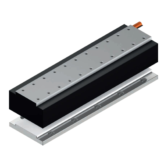
Assembly Instructions Linear Motors LMS Assembly and connection 5.2 Assemble block and forcer Fig. 5.3 Configuration of the block and forcer on the carriage Table 5.3 Components of the block with forcer Position Components Stop edge of the reference block Reference block Forcer Following block... - Page 18 Assembly Instructions Linear Motors LMS Assembly and connection 5.2.1 Assemble carriage with forcer WARNING! Risk of crushing from strong attraction forces! Risk of injury from crushing and damage to the forcer or stator due to very strong attraction forces Ensure that the forcer does not get near the stator until the linear guideway can absorb the forces! ...
-
Page 19: Electrical Connection And Protection Against Overload
Assembly Instructions Linear Motors LMS Assembly and connection 5.3 Electrical connection and protection against overload DANGER! Danger from electrical voltage! If linear motors are incorrectly earthed, there is a danger of electric shock. Before connecting the electrical power supply, ensure that the linear motor is correctly earthed! ... - Page 20 Assembly Instructions Linear Motors LMS Assembly and connection Optionally, the motor cables can be delivered with assembled plugs matching the HIWIN extension cables. Optionally with pre-assembled plug Fig. 5.9 Connecting the motor plug NOTE Maximum length of the supply cable 10 m, for intermediate circuit voltage 560 V.
- Page 21 The PTC elements located in every phase winding in HIWIN motors are wired in series; they connect via two wires.
- Page 22 Assembly Instructions Linear Motors LMS Assembly and connection 5.3.4 Extension cables NOTE If cables other than those listed are used, this may lead to damage and malfunctioning. The manufacturer shall not be liable for damages arising from use of unapproved cables. NOTE Maximum length of the supply cable 10 m, for intermediate circuit voltage 560 V.
- Page 23 Assembly Instructions Linear Motors LMS Assembly and connection 5.3.5 Hall sensors (optional) CAUTION! Risk of injury from uncontrolled motor movements! An incorrectly installed or connected Hall sensor may cause uncontrolled motor movements which can lead to injuries or might damage the machine. Hall sensor may only be connected by specialist personnel! ...
- Page 24 Assembly Instructions Linear Motors LMS Assembly and connection 5.3.5.1 Assembling the Hall sensor Use two M3 screws to secure the Hall sensor to the mounting holes provided for the forcer. If the Hall sensor is not secured directly to the forcer, but e.g. on the carriage, then the distance between the forcer and Hall sensor must always be an integral multiple of the Pole pair pitch 2τ...
- Page 25 Assembly Instructions Linear Motors LMS Assembly and connection Assignment of 9-pin Sub-D connector (cable length 500 mm): Table 5.11 Pin assignment of Hall sensor Sub-D connector Colour of Hall sensor cable Coupling M17 – pin no. Signal Drawing Blue Hall A+ Green Hall A–...
- Page 26 Assembly Instructions Linear Motors LMS Assembly and connection Analogue Hall sensor signals are analysed via a second encoder input. Tracks A and B must be modified to the counting direction and the motor’s mounted position. Hall sensor counts in the direction of the positioning measure- ment system.
-
Page 27: Commissioning
Assembly Instructions Linear Motors LMS Commissioning Commissioning 6.1 Switch on the linear motor WARNING! Risk of injury and material damage! If the motor is overloaded, it may overheat and catch fire. Provide a safety device on the control and hardware side to protect the motor against overload! ... -
Page 28: Maintenance And Cleaning
Assembly Instructions Linear Motors LMS Maintenance and cleaning Maintenance and cleaning 7.1 Maintenance WARNING! Risk of injury and material damage! Unauthorised work on the system creates the risk of injuries and may invalidate the warranty. Only qualified personnel may assemble, install, and service the system! ... -
Page 29: Faults
Assembly Instructions Linear Motors LMS Faults Faults 8.1 Faults with the motor Table 8.1 Fault table Fault Possible cause Remedy Forcer does not Supply lines disconnected Check connections, plug contacts may be start compressed, repair if necessary. The connectors have seals, which means that a certain screw connection resistance must be overcome. - Page 30 Assembly Instructions Linear Motors LMS Disposal Disposal ATTENTION! Danger caused by environmentally hazardous substances! The danger to the environment depends on the type of substance used. Clean contaminated parts thoroughly before disposal! Clarify the requirements for safe disposal with disposal companies and, where appropriate, with the ...
- Page 31 Length of stator [mm]: 0: 128 3: 320 Width of stator: Stator model: 1: Suitable for LMS13 and LMS17 2: Suitable for LMS23 and LMS27 S: Standard 3: Suitable for LMS37(L) 4: Suitable for LMS47(L) 5: Suitable for LMS57(L) 6: Suitable for LMS67(L)
- Page 32 Assembly Instructions Linear Motors LMS EU Declaration of Conformity EU Declaration of Conformity LMS-01-0-EN-2301-MA...
- Page 33 Assembly Instructions Linear Motors LMS Notes LMS-01-0-EN-2301-MA...
- Page 34 Assembly Instructions Linear Motors LMS Notes LMS-01-0-EN-2301-MA...
- Page 35 EU Declaration of Conformity...
- Page 36 Robots Linear Motors Rotary Tables Drives & Servo Motors Germany France Switzerland Netherlands China HIWIN GmbH HIWIN GmbH HIWIN Schweiz GmbH HIWIN GmbH HIWIN Corp. Brücklesbünd 1 4, Impasse Joffre Eichwiesstrasse 20 info@hiwin.nl www.hiwin.cn D-77654 Offenburg F-67202 Wolfisheim CH-8645 Jona www.hiwin.nl...
Need help?
Do you have a question about the LMS27 and is the answer not in the manual?
Questions and answers