Table of Contents
Advertisement
Quick Links
Advertisement
Table of Contents

Related Manuals for Hiwin TMRW Series


Summary of Contents for Hiwin TMRW Series
- Page 1 TMRW series Installation Manual www.servosystem.ru +7(495) 407-01-02...
-
Page 2: Table Of Contents
OTOR INSTALLATION INTRODUCTION ................. 10 TATOR INSTALLATION INTRODUCTION ......11 HE SCREW TIGHTENING TORQUE SPECIFICATION FOR STATOR ROTOR 4. TMRW MOTOR INSTALLATION PROCEDURE ............12 HIWIN’ ) ........12 TATOR OTOR MOUNTED TOGETHER WITH S FIXTURE ) ..... 13 TATOR... -
Page 3: Introduction
M01UE01-1404 1. Introduction: HIWIN TMRW series torque motor is constituted of stator and rotor. A servo-drive regulation ensures excellent acceleration capabilities and good uniformity of movement. Due to the hollow shaft design, cable systems or mechanical parts can be fed through without problems. -
Page 4: Instructions
(4) Do not apply loads to the motor that are in excess of the specified value. (5) Do not change the motor parts or disassemble the screws. HIWIN will not be responsible for any damages, injuries, or accidents that may occur. -
Page 5: Basic Structure Of Tmrw Torque Motor
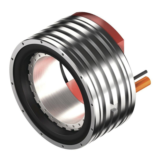
M01UE01-1404 2. Basic structure of TMRW torque motor HIWIN TMRW series torque motor is constituted solely of stator and rotor, exclusive of bearing, positioning systems and other relative parts. The main structure is as Fig. 2.1 shows and below is the description: Stator:With water cooing channels in the outer part, and it is made of aluminum alloys... -
Page 6: Tmrw Torque Motor Installation Design
M01UE01-1404 3. TMRW torque motor installation design TMRW series (As Fig. 3.1) can be cooled by water or air. There is a water cooling channels in the outer case of stator. And outside of the channels, there is an O-ring equipped to be leak proof. -
Page 7: Water Cooling Channels Dimension
M01UE01-1404 3.2 Water cooling channels dimension Fig. 3.2 is the water cooling channel dimension diagram while Table 2 defines the channel spec. for TMRW series. O-ring O-ring Fig. 3.2 Water cooling channel dimension Table 2 Water cooling channel dimension Inlet/outlet... -
Page 8: O-Ring Features
M01UE01-1404 3.3 O-ring features: Table 3 is the O-ring features for TMRW series. Table 3 O-ring features Motor O-ring O-ring internal diameter O-ring type Type thickness(mm) (mm) TMRW1x VITON 2.62 152.07 TMRW2x VITON 2.62 190.17 TMRW4x VITON 2.62 221.92 TMRW7x... -
Page 9: Coolant Inlet/Outlet Position When Mounted Vertically
M01UE01-1404 3.5 Coolant inlet/outlet position when mounted vertically Directions of inlet/outlet depend on customer but the coolant inlet/outlet must be level with the motor cable outlet. Inlet and outlet Fig. 3.4 Coolant inlet/outlet position when mounted vertically 3.6 Rotor installation introduction In order to prevent magnet interference and motor’s performance affected, there should be some space (Fig. - Page 10 M01UE01-1404 Table 4 Rotor mounting level suggestion ΦD Φd Flatness A Flatness B Motor Type (mm) (mm) (mm) (mm) TMRW1x 84.5 0.05 0.05 TMRW2x 0.05 0.05 TMRW4x TMRW7x TMRWAx 284.5 TMRWDx 0.15 0.15 www.servosystem.ru +7(495) 407-01-02...
-
Page 11: Stator Installation Introduction
M01UE01-1404 3.7 Stator installation introduction The recommended tolerance of housing’s internal diameter (and mounting holes of stator) is H7 or H8, and the flatness stator mounting level is as defined in Table 4 (Flatness B); the housing is suggested to be chamfered ( recommended dimension is as Fig. -
Page 12: The Screw Tightening Torque Specification For Stator/Rotor
M01UE01-1404 3.8 The screw tightening torque specification for stator/rotor The recommended level of the fixed screw to stator/rotor is hardness class 12.9. Below defines the types of threaded holes, quantity and tightening torque for every kind of motor. Table 5 Screw tightening torque Nominal Type of threaded Quantity of... -
Page 13: Tmrw Motor Installation Procedure
Stator/ Rotor installed together: Install with the fixed fixture and the position can be either the outlet side or the other side. Customer could consult with HIWIN sales or engineers to define the position of the fixture and confirm the drawing before placing an order. - Page 14 M01UE01-1404 4. Fix the rotor on the shaft (please refer section 3.8 for screw tightening torque spec.) 5. Loosen the screw of the fixture, and dismantle the fixture. 6. Install the bottom plate, and fasten the fixed screw of stator (please refer section 3.8 for screw tightening torque spec.) 7.
- Page 15 M01UE01-1404 4. Install O-ring to stator. Mind that the O-ring cannot be twisted during installation. 5. Place the stator into the housing, and fasten the bolt (please refer section 3.8 for the screw tightening torque ). Mind that the motor cable outlet should be aligned with the coolant outlet/inlet.
-
Page 16: Motor Cables
M01UE01-1404 5. Motor cables 5.1 Power cable specification: The standard length of power cable and temperature sensor cable is 2000mm±50mm (as Fig. 5.1), excluding the metal connector of the outlet. Customers can have the options to choose other lengths. Every extra 1m is the standard length for other options, with the longest length up to 8m. -
Page 17: Temperature Sensor Cable Specification
M01UE01-1404 5.2 Temperature sensor cable specification Every motor is equipped with a set of SNM100 and a set of SNM 120 temperature sensor and also one in every phase (there are three sensors each set). KTY84-130 sensor installs in U phase, and with electrostatic discharge protection facility. The cross sectional area is 0.25mm for every cable. -
Page 18: Temperature Sensor Features
M01UE01-1404 5.3 Temperature sensor features KTY84-130 is a type of silicon sensor that can measure the output resistance value to get the actual temperature. The feature is shown in Table 8, and the resistance value change against the temperature is shown in Fig. 5.5 . Table 8 KTY84-130 sensor features Symbol Parameter... - Page 19 M01UE01-1404 Fig. 5.6 PTC’s relationship between temperature and resistance value www.servosystem.ru +7(495) 407-01-02...
-
Page 20: Radial Forces Between The Stator And The Rotor
M01UE01-1404 6. Radial forces between the stator and the rotor When the concentricity of the stator and rotor is offset, radial forces will generate like Fig. 6.1 and Table 10 defines the value of radial force for every motor. Fig. 6.1 Offset concentricity of the stator and rotor Table 10 Radial force value Radial force f Motor... -
Page 21: Safety Precautions
(4) Do not apply loads to the motor that are in excess of the specified value. (5) Do not change the motor parts or disassemble the screws. HIWIN will not be responsible for any damages, injuries, or accidents that may occur. -
Page 22: Wiring Instructions
M01UE01-1404 7.2 Wiring instructions: (1) Ensure the specified power input value before using the product, and verify that the proper power supply is being used. (2) Before operation, please ensure that the motor are connected correctly. Incorrect wiring may cause abnormal motor operation or even cause permanent damage to the motor. -
Page 23: Troubleshooting
M01UE01-1404 8. Troubleshooting: Malfunction characteristic Possible fault cause Elimination method Check the wiring and Motor cannot rotate Some of the wiring is incorrect specification is correct Encoder setting is incorrect Check the drive model is correct. Motor rotate in the wrong direction Input phase error Cross 2 phases of the motor.
Need help?
Do you have a question about the TMRW Series and is the answer not in the manual?
Questions and answers