Table of Contents
Advertisement
Quick Links
Advertisement
Table of Contents
Troubleshooting

Related Manuals for Hiwin MIKROSYSTEM E Series


Summary of Contents for Hiwin MIKROSYSTEM E Series
- Page 1 E Series AC Servo Motor User Manual www.hiwinmikro.tw MC03UE01-2309_V1.2...
- Page 2 Related Documents Through related documents, users can quickly understand the positioning of this manual and the correlation between manuals and products. Go to HIWIN MIKROSYSTEM’s official website (https://www.hiwinmikro.tw/Downloads/ManualOverview_EN.htm) → Download → Manual Overview for details.
- Page 3 Approvals Approvals Drive Motor EN61800-3 EN55011 EN61000-6-2 EN55011 EN61000-6-2 EMC requirement EN61000-6-4 CE requirement EN61000-2-4 EN61000-6-4 IEC60146-1-1 IEC61000-2-1 EN60034-1 Low voltage requirement LVDS:EN61800-5-1 EN60034-5 UL1004-1 UL requirement UL:E348161 UL1004-6...
-
Page 4: Table Of Contents
Table of Contents General information ............................1-1 Revision history ..........................1-2 About this manual ........................... 1-4 General precautions ........................1-5 Safety instruction ........................... 1-11 Copyright ............................1-15 Manufacturer information ......................1-15 Product monitoring ........................1-15 Basic safety information ........................... 2-1 Overview ............................ - Page 5 3.3.2.7 EM1-D-M-1A-2-□-□-0-□−technical data ..............3-18 3.3.2.8 EM1-D-M-2K-2-□-□-0-□−technical data ..............3-19 3.3.3 Mechanical overview ......................3-21 3.3.4 Selection calculation ......................3-24 3.3.4.1 Mechanical mechanism ....................3-24 3.3.4.2 Motion profile ....................... 3-26 3.3.4.3 Load inertia calculation ....................3-27 3.3.4.4 Motor speed calculation ....................3-28 3.3.4.5 Motor torque calculation ....................
- Page 6 Commissioning ..............................6-1 Commissioning ..........................6-2 6.1.1 Flow chart for tuning ......................6-2 6.1.2 Tuning function ........................6-3 6.1.3 Precautions during tuning ...................... 6-4 Maintenance and cleaning ..........................7-1 Maintenance ........................... 7-2 Cleaning ............................7-4 7.2.1 Test run ..........................7-5 Disposal ................................
-
Page 7: General Information
1. General information General information ............................1-1 Revision history ..........................1-2 About this manual ........................... 1-4 General precautions ........................1-5 Safety instruction ........................... 1-11 Copyright ............................1-15 Manufacturer information ......................1-15 Product monitoring ........................1-15 HIWIN MIKROSYSTEM CORP. -
Page 8: Revision History
15. Update section 5.2.1.2 17 bit / 23 bit Incremental encoder cable connector. 16. Update section 5.2.1.3 17 bit / 23 bit Absolute encoder cable connector. 17. Update section 7.1 Maintenance. 18. Delete section 7.2.1.1 Inspection procedure for servo motor. HIWIN MIKROSYSTEM CORP. - Page 9 21. Add section 11.5.3 Accessories for absolute encoder. 22. Add section 11.5.4 Regenerative resistor. May. 31 , 2023 E Series AC Servo Motor Rearrange the chapters. Mar. 6 , 2020 E Series AC Servo Motor First edition. HIWIN MIKROSYSTEM CORP.
-
Page 10: About This Manual
Be sure to refer to this manual and to keep this manual in a location where it can be accessed at any time. Documents For configuring, you require the catalog or manual as print version or online with the following website. https://www.hiwinmikro.tw/en/product/ac-servo-motor/ac-servo-motor-e1-series HIWIN MIKROSYSTEM CORP. -
Page 11: General Precautions
General information 1.3 General precautions Before using the product, please carefully read through this manual. HIWIN MIKROSYSTEM is not responsible for any damage, accident or injury caused by failure in following the installation instructions and operating instructions stated in this manual. - Page 12 If the information of registration does not match with your purchasing or if there are any questions related to the product, please contact the sales representatives of HIWIN MIKROSYSTEM or agents or dealers. HIWIN MIKROSYSTEM offers 1-year warranty for the product. The warranty does not cover damage caused by improper usage (refer to the precautions and instructions stated in this manual) or natural disaster.
- Page 13 Ensure the AC servo motor is correctly grounded. The resistance of grounding terminal connection shall be less than 10Ω when the input voltage of the drive is 400V; less than 50Ω when it is 220V; less than 100Ω when it is 110V. HIWIN MIKROSYSTEM CORP.
- Page 14 If no dry storage environment is available, the following measures need to be taken: Wrap the motor with moisture-absorbing material, and then seal the motor. Put desiccant in the sealed package; the desiccant needs to be checked and replaced if necessary. Check the AC servo motor regularly. HIWIN MIKROSYSTEM CORP.
- Page 15 Transportation Conditions Environmental parameter Description Air temperature -15°C~70°C Relative humidity 20%~80% Rate of change of temperature 0.5°C /min Condensation Not allowed Formation of ice Not allowed Transport the motor in an environment with good protection. (indoor/factory) HIWIN MIKROSYSTEM CORP.
- Page 16 WARNING Risk of personal injury or damage to property. Do not disassemble or modify the product. If the product malfunctions, do not repair the product by yourselves, please contact HIWIN MIKROSYSTEM for repairs. Disposal precautions WARNING Risk of personal injury or damage to property.
-
Page 17: Safety Instruction
Indicates that minor personal injury can result if proper precautions are not taken. Warning Signs No access for people with active Substance hazardous to the implanted cardiac devices. environment! Warning! Warning of crushing of hands! Warning of electricity! Warning of hot surface! Warning of magnetic field! HIWIN MIKROSYSTEM CORP. 1-11... - Page 18 Do not repair the product by yourselves if something abnormal occurs. The product can only be repaired by HIWIN MIKROSYSTEM qualified technicians or sent back to HIWIN MIKROSYSTEM for repairs. Do not apply the load exceeding the specification standards to the product.
- Page 19 Do not use the product in an environment where it may be shocked. Do not directly strike the shaft or encoder, as hitting or pounding. HIWIN MIKROSYSTEM is not responsible for any damage, accident or injury caused by this.
- Page 20 Strong magnetic force may destroy watches and magnetizable data storage media near Do not bring watches or magnetizable data storage media in the vicinity (<300 mm) of the AC servo motor! the AC servo motor! 1-14 HIWIN MIKROSYSTEM CORP.
-
Page 21: Copyright
This user manual is protected by copyright. Any reproduction, publication in whole or in part, modification or abridgement requires the written approval of HIWIN MIKROSYSTEM. Note: HIWIN MIKROSYSTEM reserves the right to change the contents of this manual or product specifications without prior notice. 1.6 Manufacturer information Table 1.6.1 Manufacturer’s details... - Page 22 MC03UE01-2309 General information E Series AC Servo Motor User Manual (This page is intentionally left blank.) 1-16 HIWIN MIKROSYSTEM CORP.
- Page 23 Basic safety information ........................... 2-1 Overview ............................2-2 Basic safety notices ........................2-2 Reasonably foreseeable misuse ....................2-3 Conversions and modifications ....................... 2-3 Residual risks ..........................2-3 Personnel requirements........................2-4 Protective equipment ........................2-4 Labels on servo motor ........................2-5 HIWIN MIKROSYSTEM CORP.
-
Page 24: Basic Safety Information
Do not use the product in an environment with corrosive, flammable gases or flammable materials. Do not touch the surface of the AC servo motor, servo drive or regenerative resistor which will be hot while operating. HIWIN MIKROSYSTEM CORP. -
Page 25: Reasonably Foreseeable Misuse
WARNING Risk of personal injury or damage to property. Conversions or modifications to AC servo motor are prohibited. Modifications of AC servo motor are not permitted. Please contact HIWIN MIKROSYSTEM for special request. 2.5 Residual risks CAUTION Personal injury or damage to property. -
Page 26: Personnel Requirements
Trained specialist personnel of the dealer or manufacturer Repairs Trained specialist personnel of the dealer or manufacturer 2.7 Protective equipment Possible safety equipment/measures: Personal protective equipment in accordance with regional regulations. Zero-contact protective equipment. Mechanical protective equipment. HIWIN MIKROSYSTEM CORP. -
Page 27: Labels On Servo Motor
2.8 Labels on servo motor Nameplate Product name CE mark Motor type Part no. Input spec. UL mark Output spec. Serial No. QR mark Company address Figure 2.8.1 Location of safety symbols on motor Figure 2.8.2 HIWIN MIKROSYSTEM CORP. - Page 28 MC03UE01-2309 Basic safety information E Series AC Servo Motor User Manual (This page is intentionally left blank.) HIWIN MIKROSYSTEM CORP.
-
Page 29: Product Description
Motion profile ....................... 3-26 3.3.4.3 Load inertia calculation ....................3-27 3.3.4.4 Motor speed calculation ....................3-28 3.3.4.5 Motor torque calculation ....................3-29 3.3.4.6 Regenerative energy calculation ................. 3-31 3.3.5 Operating instructions ......................3-33 3.3.6 De-rating curve........................3-34 HIWIN MIKROSYSTEM CORP. -
Page 30: Servo Motor Description
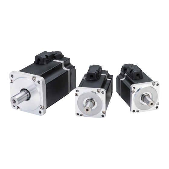
E series servo drive, that can effectively improve production efficiency. 50 W ~ 750 W AC servo motor appearance is shown as below: Figure 3.1.1 1 kW ~ 2 kW AC servo motor appearance is shown as below: Figure 3.1.2 HIWIN MIKROSYSTEM CORP. -
Page 31: Main Components Of Servo Motor
MC03UE01-2309 E Series AC Servo Motor User Manual Product description 3.2 Main components of servo motor Table 3.2.1 Combination of HIWIN AC servo motors and servo drives Servo Motor Model Rated Output Rated Torque Rated Speed Servo Drive Model ED1□-□□-0422-A□... -
Page 32: Order Code
A = Round shaft / without oil seal B = Round shaft / with oil seal 12: Shaft type C = Shaft with key / without oil seal D = Shaft with key / with oil seal HIWIN MIKROSYSTEM CORP. -
Page 33: E1 Series Servo Drive
1, 2, 3: E1 Series Servo Drive 4: Type S = Standard F = Fieldbus E = EtherCAT (CoE) H = mega-ulink (with HIWIN MoE HIMC motion controller or API/MPI motion control 5: Control Interface V = Voltage command and pulse command library) - Page 34 (11) ED1□-□□-□□□□-T1-□□ is a GT servo drive, its functions are as follows: 1. Support nano precision function. 2. Support 2D Error map (with ED1□-□G-□□□□-T1-□□). Gantry function cannot be used while users enable 2D Error map. 3. Support DC 96-120V. HIWIN MIKROSYSTEM CORP.
-
Page 35: E2 Series Servo Drive
4: Type S = Standard F = Fieldbus E0 = EtherCAT (CoE) V0 = Voltage command and H3 = mega-ulink (with HIWIN MoE HIMC 5, 6: Control Interface pulse motion controller or API/MPI motion control command library) 003 = 3 Arms 7, 8, 9: Rated Output 006 = 6.3 Arms... -
Page 36: Power Cable
Cable length can be customized for integer such as 1M, 2M, 3M…30M. Information about pin assignment and connector specification can be referred to section 5.2.1. Information about bending radius limitation of power cable can be referred to section 5.2.1.4. HIWIN MIKROSYSTEM CORP. -
Page 37: Encoder Cable
Cable length can be customized for integer such as 1M, 2M, 3M…30M. Inforamtion about pin assignment and connector specification can be referred to section 5.2.1. Inforamtion about bending radius limitation of power cable can be referred to section 5.2.1.4. HIWIN MIKROSYSTEM CORP. -
Page 38: Combination Of E Series Ac Servo Motor, Servo Drives And Cable
HVPM04□B□□MB HVE23I□B□□MB EM1AM1K2BE0□ HVPM06□B□□MB 1 kW EM1AM1K20F0□ HVPM04□B□□MB HVE23A□B□□MB EM1AM1K2BF0□ HVPM06□B□□MB EM1DM1A20E0□ HVPM04□B□□MB HVE23I□B□□MB EM1DM1A2BE0□ HVPM06□B□□MB 1.2 kW EM1DM1A20F0□ HVPM04□B□□MB HVE23A□B□□MB EM1DM1A2BF0□ HVPM06□B□□MB ED1□-□□-2022-A□ EM1DM2K20E0□ HVPM04□B□□MB HVE23I□B□□MB EM1DM2K2BE0□ HVPM06□B□□MB 2 kW EM1DM2K20F0□ HVPM04□B□□MB HVE23A□B□□MB EM1DM2K2BF0□ HVPM06□B□□MB 3-10 HIWIN MIKROSYSTEM CORP. - Page 39 HVE23IAB□□MB EM1CM752BC0□ HVPS06AA□□MB 750 W EM1CM7520D0□ HVPS04AA□□MB HVE23AAB□□MB EM1CM752BD0□ HVPS06AA□□MB ED2□-□□-006-1-A- EM1AM1K20C0□ HVPM04□A□□MB HVE23I□B□□MB EM1AM1K2BC0□ HVPM06□A□□MB 1 kW EM1AM1K20D0□ HVPM04□A□□MB HVE23A□B□□MB EM1AM1K2BD0□ HVPM06□A□□MB EM1DM1A20C0□ HVPM04□A□□MB HVE23I□B□□MB EM1DM1A2BC0□ HVPM06□A□□MB ED2□-□□-009-1-A- 1.2 kW EM1DM1A20D0□ HVPM04□A□□MB HVE23A□B□□MB EM1DM1A2BD0□ HVPM06□A□□MB HIWIN MIKROSYSTEM CORP. 3-11...
-
Page 40: Technical Data
Brake input voltage DC 24±10% Braking time Release time 6000, 0.62 0, 0.62 S1 (3-Phase) S3 (3-Phase) S1(Single Phase) S3(Single Phase) 0, 0.159 3000, 0.159 6000, 0.0795 1000 2000 3000 4000 5000 6000 7000 Speed(rpm) Figure 3.3.2.1.1 3-12 HIWIN MIKROSYSTEM CORP. -
Page 41: Em1-C-M-10-2-□-□-0-□−Technical Data
Brake rated current 0.25 Brake input voltage DC 24±10% Braking time Release time 4600, 1.197 S1 (3-Phase) 6000, 0.874 S3 (3-Phase) S1(1-Phase) S3(1-Phase) 3000, 0.318 6000, 0.159 1000 2000 3000 4000 5000 6000 Speed(rpm) Figure 3.3.2.2.1 HIWIN MIKROSYSTEM CORP. 3-13... -
Page 42: Em1-C-M-20-2-□-□-0-□−Technical Data
Braking time Release time 5000, 2.24 0, 2.24 S1 (3-Phase) 6000, 1.87 S3 (3-Phase) 6000, 1.76 S1 (1-Phase) S3 (1-Phase) 0, 0.64 3000, 0.64 6000, 0.32 1000 2000 3000 4000 5000 6000 7000 Speed (rpm) Figure 3.3.2.3.1 3-14 HIWIN MIKROSYSTEM CORP. -
Page 43: Em1-C-M-40-2-□-□-0-□−Technical Data
3800, 4.44 4000, 4.44 0, 4.44 S1 (3-Phase) 5000, 3.51 S3 (3-Phase) 6000, 2.92 S1 (Single-Phase) S3 (Single-Phase) 6000, 2.27 0, 1.27 3000, 1.27 6000, 0.638 1000 2000 3000 4000 5000 6000 7000 Speed (rpm) Figure 3.3.2.4.1 HIWIN MIKROSYSTEM CORP. 3-15... -
Page 44: Em1-C-M-75-2-□-□-0-□−Technical Data
Release time 4108, 8.36 4267, 8.36 0, 8.36 S1 (3-Phase) S3 (3-Phase) S1 (1-Phase) 6000, 5.43 6000, 5.2 S3 (1-Phase) 0, 2.39 3000, 2.39 6000, 1.2 1000 2000 3000 4000 5000 6000 7000 Speed (rpm) Figure 3.3.2.5.1 3-16 HIWIN MIKROSYSTEM CORP. -
Page 45: Em1-A-M-1K-2-□-□-0-□−Technical Data
Release time S1 (3-Phase) 2000, 14.3 0, 14.3 S3 (3-Phase) S1 (1-Phase) S3 (1-Phase) 1925, 11.59 0, 4.77 2000, 4.77 3000, 5 3000, 2.77 3000, 2.385 1000 1500 2000 2500 3000 3500 Speed (rpm) Figure 3.3.2.6.1 HIWIN MIKROSYSTEM CORP. 3-17... -
Page 46: Em1-D-M-1A-2-□-□-0-□−Technical Data
DC 24±10% Braking time Release time S1 (3-Phase) 2500, 16 S3 (3-Phase) S1 (1-Phase) 2500, 14.7 S3 (1-Phase) 5000, 8.3 2000, 5.7 5000, 6.4 4500, 2.5 1000 2000 3000 4000 5000 6000 Speed (rpm) Figure 3.3.2.7.1 3-18 HIWIN MIKROSYSTEM CORP. -
Page 47: Em1-D-M-2K-2-□-□-0-□−Technical Data
0, 30 2500, 30 S3 (3-Phase) S1 (1-Phase) 2000, 23 S3 (1-Phase) 5000, 15 0, 9.55 2000, 9.55 4500, 5 2000, 7.2 0, 7.2 4500, 4.3 1000 2000 3000 4000 5000 6000 Speed (rpm) Figure 3.3.2.8.1 HIWIN MIKROSYSTEM CORP. 3-19... - Page 48 * indicates motor shaft and connector are not included.(If the motor shaft needs IP protection, oil seal is necessary). The nominal motor properties are all single-phase/three-phase 220V input power. Please contact the sales representatives of HIWIN MIKROSYSTEM if you need 110V motor properties. 3-20 HIWIN MIKROSYSTEM CORP.
-
Page 49: Mechanical Overview
MC03UE01-2309 E Series AC Servo Motor User Manual Product description 3.3.3 Mechanical overview EM1-C-M-05-2-□-□-0-□ Figure 3.3.3.1 EM1-C-M-10-2-□-□-0-□ Figure 3.3.3.2 EM1-C-M-20-2-□-□-0-□ Figure 3.3.3.3 HIWIN MIKROSYSTEM CORP. 3-21... - Page 50 MC03UE01-2309 Product description E Series AC Servo Motor User Manual EM1-C-M-40-2-□-□-0-□ Figure 3.3.3.4 EM1-C-M-75-2-□-□-0-□ Figure 3.3.3.5 EM1-A-M-1K-2-□-□-0-□ Figure 3.3.3.6 3-22 HIWIN MIKROSYSTEM CORP.
- Page 51 MC03UE01-2309 E Series AC Servo Motor User Manual Product description EM1-D-M-1A-2-□-□-0-□ Figure 3.3.3.7 EM1-D-M-2K-2-□-□-0-□ Figure 3.3.3.8 Note: Motor shaft and connector are not included.(If the motor shaft needs IP protection, oil seal is necessary) HIWIN MIKROSYSTEM CORP. 3-23...
-
Page 52: Selection Calculation
���� Peak torque (��������) Inner diameter (����) ���� ���� ���� Travelling torque (��������) Length (����) ���� a, b, c Work pieces amount (pcs) Side length (����) ���� ���� ���� ���� Acceleration torque (��������) Deceleration torque (��������) 3-24 HIWIN MIKROSYSTEM CORP. - Page 53 Work pieces weight / Belt weight Belt tension force (F Rotary table Installation direction: horizontal or vertical Table dimension / weight Work pieces weight / quantities Distance from work pieces to rotation axis HIWIN MIKROSYSTEM CORP. 3-25...
-
Page 54: Motion Profile
MC03UE01-2309 Product description E Series AC Servo Motor User Manual 3.3.4.2 Motion profile Trapezoidal profile Figure 3.3.4.2.1 Triangle profile Figure 3.3.4.2.2 3-26 HIWIN MIKROSYSTEM CORP. -
Page 55: Load Inertia Calculation
+ n × (J + WD It is suggested to keep the load inertia ratio below 15 times of normal operation: (���� + ���� ���������������� ���� ���� ���������������� ���� ���������������� ���� = < �������� ���� ���� ���� ���� HIWIN MIKROSYSTEM CORP. 3-27... -
Page 56: Motor Speed Calculation
ω ∶ angular velocity ( π Motor calculation speed should be within motor continuous work range. E.g., As the T-N curve shows below, 3000 rpm is the continuous work range of motor speed. Figure 3.3.4.4.1 3-28 HIWIN MIKROSYSTEM CORP. -
Page 57: Motor Torque Calculation
�������������������� ���� ���������������� ���� ���� ������������������������ < ����. ���� × �������������������� ���������������� ���� ���� ���������������� Its is suggested to keep motor calculation equivalent torque below 80% of motor rated torque. ���������������� ���� �������� ���� �������� ������������������������ < ����. ���� × �������������������� �������������������� ���� ���� ���������������� HIWIN MIKROSYSTEM CORP. 3-29... - Page 58 MC03UE01-2309 Product description E Series AC Servo Motor User Manual Figure 3.3.4.5.1 3-30 HIWIN MIKROSYSTEM CORP.
-
Page 59: Regenerative Energy Calculation
���� ���� ���� ���� − ( ���� ) + ���� ���� + ���� + ���� Step 6: Calculate energy (capacity) consumed by the regenerative resistor (PR). ���� ���� ���� ���� ���� ���� ���� ���� ���� HIWIN MIKROSYSTEM CORP. 3-31... - Page 60 Total inertia (motor + load) Motor speed Load torque Deceleration time Motor current during deceleration Motor resistance Drive capacitance drive Voltage at regeneration Voltage from DC bus main Motor torque during regeneration Time during regeneration Cycle time Joule Watt 3-32 HIWIN MIKROSYSTEM CORP.
-
Page 61: Operating Instructions
Do not touch the surface of the AC servo motor, servo drive or regenerative resistor which will be hot while operating. WARNING Personal injury or damage to property. The environment temperature will rise due to motor operation. AC servo motor grounding terminal must be installed properly. HIWIN MIKROSYSTEM CORP. 3-33... -
Page 62: Rating Curve
Figure 3.3.6.9. Table 3.3.6.1 Heat Sink Size AC servo motor (Material) EM1-C-M-05 200(L)*200(W)*6(T)mm EM1-C-M-10 Aluminum Alloys EM1-C-M-20 250(L)*250(W)*6(T)mm EM1-C-M-40 Aluminum Alloys EM1-C-M-75 EM1-A-M-1K 300(L)*300(W)*6(T)mm EM1-D-M-1A Aluminum Alloys EM1-D-M-2K Figure 3.3.6.1 EM1-C-M-05 (50 W) 3-34 HIWIN MIKROSYSTEM CORP. - Page 63 MC03UE01-2309 E Series AC Servo Motor User Manual Product description Figure 3.3.6.2 EM1-C-M-10 (100 W) Figure 3.3.6.3 EM1-C-M-20 (200 W) Figure 3.3.6.4 EM1-C-M-40 (400 W) HIWIN MIKROSYSTEM CORP. 3-35...
- Page 64 MC03UE01-2309 Product description E Series AC Servo Motor User Manual Figure 3.3.6.5 EM1-C-M-75 (750 W) Figure 3.3.6.6 EM1-A-M-1K (1 kW) Figure 3.3.6.7 EM1-D-M-1A (1.2 kW) 3-36 HIWIN MIKROSYSTEM CORP.
- Page 65 MC03UE01-2309 E Series AC Servo Motor User Manual Product description Figure 3.3.6.8 EM1-D-M-2K (2 kW) Figure 3.3.6.9 Heat sink size VS Load ratio HIWIN MIKROSYSTEM CORP. 3-37...
- Page 66 MC03UE01-2309 Product description E Series AC Servo Motor User Manual (This page is intentionally left blank.) 3-38 HIWIN MIKROSYSTEM CORP.
- Page 67 Delivery state ......................... 4-2 4.1.2 Scope of delivery........................4-2 4.1.3 Delivery ambient conditions ....................4-2 Transport to the installation site ...................... 4-3 Requirements at the installation site ....................4-4 Storage ............................4-5 Unpacking and setup ........................4-6 HIWIN MIKROSYSTEM CORP.
-
Page 68: Transport And Setup
Not allowed Formation of ice Not allowed Delivery the motor in an environment with good protection. (indoor/factory) Note: Avoid exposing to direct sunlight. Keep away from electric magnetic interference source sites such as welding and discharge machines. HIWIN MIKROSYSTEM CORP. -
Page 69: Transport To The Installation Site
Risk of damage to the AC servo motor! The AC servo motor may be damaged by mechanical loading. No heavy load on the cover! During transportation, do not put any additional loads on the AC servo motors. HIWIN MIKROSYSTEM CORP. -
Page 70: Requirements At The Installation Site
No interference from corrosive solvent or strong magnetic Grounding Plant power grounding line conforms to international requirements Note: Avoid exposing to direct sunlight. Keep away from electric magnetic interference source sites such as welding and discharge machines. HIWIN MIKROSYSTEM CORP. -
Page 71: Storage
-15°C ~ 70°C Relative humidity 20% ~ 80% Rate of change of temperature 0.5°C /min Air pressure 70kPa ~ 106kPa Condensation Not allowed Formation of ice Not allowed Store the motor in an environment with good protection. (indoor/factory) HIWIN MIKROSYSTEM CORP. -
Page 72: Unpacking And Setup
Step 4: Carefully handle the outgoing line from the AC servo motor. Do not bend or pull the wiring. Step 5: Ensure the appearance and nameplate on AC servo motor are the same with the catalogue. Step 6: Dispose of packaging in an environmentally friendly way. HIWIN MIKROSYSTEM CORP. -
Page 73: Assembly And Connection
Motor power cable connector ..................5-17 5.2.1.2 17 bit / 23 bit Incremental encoder cable connector ........... 5-21 5.2.1.3 17 bit / 23 bit Absolute encoder cable connector ............5-23 5.2.1.4 Allowable bending radius .................... 5-27 5.2.2 Electrical connection ......................5-28 HIWIN MIKROSYSTEM CORP. -
Page 74: Mechanical Installation
(5) The AC servo motor shaft material is not rust-resistant. Grease has been applied to prevent rust before the products were shipped. However, if the storage time exceeds six months, inspect the shaft every three months to make sure that it is not rusted. Apply an appropriate amount of rust-prevention grease when needed. HIWIN MIKROSYSTEM CORP. -
Page 75: Tools And Equipment
Oil seal Hand press machine Belt Screwdriver or wrench Cable Personal protective equipment In the vicinity of linear actuator systems, the following personal protective equipment is required: (1) Safety shoes. (2) Protective helmet. (3) Protective gloves. HIWIN MIKROSYSTEM CORP. -
Page 76: Servo Motor Installation
3.28 N-m(33.4 ) ±10% Aluminum plate 250x250x6 kgf-cm 750 W 2*M6x20L 5.58 N-m(56.9 ) ±10% Aluminum plate 400x400x20 kgf-cm 13.5 N-m(138 ) ±10% 1 kW ~ 2 kW 2*M8x20L Iron plate Note: 1 N-m ≒ 10.1972 kgf-cm HIWIN MIKROSYSTEM CORP. - Page 77 Protective structure HIWIN servo motor protective structure is described below. (1) 50 W ~ 750 W: IP65 Except for power connector, encoder connector, shaft section of the motor also needs to add oil seal, which is optional for all types of AC servo motor.
- Page 78 (5) Make sure that the assembly can be carried out in a dry and dust-free environment. (6) Make sure that the holder of the motor flange is deburred. (7) Remove the protective sleeve of the motor shaft and keep it for further use. HIWIN MIKROSYSTEM CORP.
-
Page 79: Oil Seal
Check the operation environment to make sure that the oil seal material is appropriate. The usage of oil seal should not be lower than the oil surface. The oil may leak in through the opening of motor flange to damage the AC servo motor. Figure 5.1.3.2.1 HIWIN MIKROSYSTEM CORP. -
Page 80: Key
(4) Press the key into the keyway. Figure 5.1.3.3.1 (5) Lean the shaft on a solid surface and make sure to press the key vertically. The velocity of pressing should be under 400mm/min. Punching is prohibited. Figure 5.1.3.3.2 HIWIN MIKROSYSTEM CORP. - Page 81 Uninstallation procedures: 50 W / 100 W Step 1: Remove plastic cover from the shaft. Step 2: Prepare diagonal pliers. Step 3: Clip the key with the pliers. Step 4: Remove the key from the shaft. HIWIN MIKROSYSTEM CORP.
- Page 82 CAUTION Risk of personal injury or damage to property. Be sure that the key is pressed vertically. Be careful with the sharp keyway when cleaning or installing the key. 5-10 HIWIN MIKROSYSTEM CORP.
-
Page 83: Belt
Please refer to the following information. Figure 5.1.3.4.1 Motor shaft allowable axial and radial force. Figure 5.1.3.4.2 (Allowable axial force): Table 5.1.3.4.1 Flange size Allowable axial force 40mm 60mm 80mm 147N 130mm 343N HIWIN MIKROSYSTEM CORP. 5-11... -
Page 84: Coupling
This is an easy way to check the concentricity between the two. If this method cannot be adopted, please use machine part precision management or other methods to ensure installation accuracy. Axial Rotational direction direction Figure 5.1.3.5.1 5-12 HIWIN MIKROSYSTEM CORP. - Page 85 Conduct installation only when the main power is OFF. When installing the motor, be awrae of the following three types of basic deviation, as shown below: 1. Eccentricity(A): 3. Axial direction displacement (C): 2. Declination(B): Figure 5.1.3.5.3 HIWIN MIKROSYSTEM CORP. 5-13...
- Page 86 Therefore, make sure that the deviation between the two axes are within the coupling’s allowable deviation. When choosing a coupling, it is recommended to choose a flexible coupling that can absorb the eccentricity, declination and axial direction displacement. 5-14 HIWIN MIKROSYSTEM CORP.
-
Page 87: Safety Brakes
(3) Noise: when the motor is operating at a low rotation, accelerating, stopping or changing directions, sometimes the friction plate will produce a noise. This is not a malfunction noise but a sound from the brake module structure, which will not affect motor function. HIWIN MIKROSYSTEM CORP. 5-15... - Page 88 (1) Check if the ON/OFF operation is correct. (2) Check if there are any noises. (3) Check if there is abnormal heating. (4) Check if the release time is abnormal. (5) Check if the input voltage is correct. 5-16 HIWIN MIKROSYSTEM CORP.
-
Page 89: Electrical Installation
(with brake) European terminal 18AWG 2.8mm White White European terminal 18AWG 2.8mm Black Black European terminal 18AWG 2.8mm Green Green R type terminal 18AWG 2.8mm Yellow European terminal 18AWG 2.8mm Blue European terminal 18AWG 2.8mm Figure 5.2.1.1.1 HIWIN MIKROSYSTEM CORP. 5-17... - Page 90 White White European terminal 18AWG 2.8mm Black Black European terminal 18AWG 2.8mm Green Green European terminal 18AWG 2.8mm Yellow European terminal 18AWG 2.8mm Blue European terminal 18AWG 2.8mm European type terminal European type terminal Figure 5.2.1.1.2 5-18 HIWIN MIKROSYSTEM CORP.
- Page 91 Conductors Insulators WPS3108A18-10S-R WPS3108A14S-7S-R European terminal 14AWG 3.6mm White European terminal 14AWG 3.6mm Black European terminal 14AWG 3.6mm Green R type terminal 14AWG 3.6mm White European terminal 20AWG 1.8mm Black European terminal 20AWG 1.8mm Figure 5.2.1.1.3 HIWIN MIKROSYSTEM CORP. 5-19...
- Page 92 14AWG 3.6mm Black European terminal 14AWG 3.6mm Green European terminal 14AWG 3.6mm White European terminal 20AWG 1.8mm Black European terminal 20AWG 1.8mm European type terminal European type terminal European type terminal European type terminal Figure 5.2.1.1.4 5-20 HIWIN MIKROSYSTEM CORP.
-
Page 93: Bit / 23 Bit Incremental Encoder Cable Connector
Function Signal Color Conductors Insulators AMP 170359-1 3M 36210 Blue (Red) 24AWG 1.3mm Power Blue (Black) 24AWG 1.3mm Yellow (Red) 24AWG 1.3mm Serial Data Signal Yellow (Black) 24AWG 1.3mm Shielding Shielding Black Housing Shielding Figure 5.2.1.2.1 HIWIN MIKROSYSTEM CORP. 5-21... - Page 94 Function Signal Color Conductors Insulators WPS 3108A18-1S-R 3M 36210 Blue (Red) 24AWG 1.3mm Power Blue (Black) 24AWG 1.3mm Yellow (Red) 24AWG 1.3mm Serial Data Signal Yellow (Black) 24AWG 1.3mm Shielding Shielding Black Housing Shielding Figure 5.2.1.2.2 5-22 HIWIN MIKROSYSTEM CORP.
-
Page 95: Bit / 23 Bit Absolute Encoder Cable Connector
Blue (Red) 24AWG 1.3mm Power Blue (Black) 24AWG 1.3mm Green (Red) 24AWG 1.3mm Battery Green (Black) Black 24AWG 1.3mm Yellow (Red) 24AWG 1.3mm Serial Data Signal Yellow (Black) 24AWG 1.3mm Shielding Shielding Black Housing Shielding Figure 5.2.1.3.1 HIWIN MIKROSYSTEM CORP. 5-23... - Page 96 1.3mm Power Blue (Black) 24AWG 1.3mm Green (Red) 24AWG 1.3mm Battery Green (Black) Black 24AWG 1.3mm Yellow (Red) 24AWG 1.3mm Serial Data Signal Yellow (Black) 24AWG 1.3mm Shielding Shielding Black Housing Shielding Figure 5.2.1.3.2 Figure 5.2.1.3.3 5-24 HIWIN MIKROSYSTEM CORP.
- Page 97 Step5: Turn off the control power of the servo drive to clear alarm AL.810. Step6: Turn on the control power of the servo drive again. Step7: Check if the alarm is cleared. Then, the servo drive can be operated normally. Figure 5.2.1.3.4 HIWIN MIKROSYSTEM CORP. 5-25...
- Page 98 110 uA power consumption (year) = (10H × A + 0.0014H × B + 2H × C) × 2 × 313 + 24H × C × 52 = 319(mAh) 1440mAh Battery life = = 4.5(year) 319mAh 5-26 HIWIN MIKROSYSTEM CORP.
-
Page 99: Allowable Bending Radius
10.5 131.25 50 W ~ 750 W Extension power cable (1 kW / 2 kW) HVPM04 10.5 131.25 Extension brake cable (1 kW / 2 kW) HVPM02 Extension encoder cable (50 W ~ 2 kW) HVE23 HIWIN MIKROSYSTEM CORP. 5-27... -
Page 100: Electrical Connection
E Series AC Servo Motor User Manual 5.2.2 Electrical connection Before connection, it is required to use HIWIN power cables and encoder cables, which have numerous advantages of UL/CSA authorization, extreme load capability and resistance as well as a design suitable for EMC. - Page 101 The resistance of grounding terminal connection shall be less than 10Ω when the input voltage of the drive is 400V; less than 50Ω when it is 220V; less than 100Ω when it is 110V. HIWIN MIKROSYSTEM CORP. 5-29...
- Page 102 MC03UE01-2309 Assembly and connection E Series AC Servo Motor User Manual (This page is intentionally left blank.) 5-30 HIWIN MIKROSYSTEM CORP.
-
Page 103: Commissioning
6. Commissioning Commissioning ..............................6-1 Commissioning ..........................6-2 6.1.1 Flow chart for tuning ......................6-2 6.1.2 Tuning function ........................6-3 6.1.3 Precautions during tuning ...................... 6-4 HIWIN MIKROSYSTEM CORP. -
Page 104: Flow Chart For Tuning
Start Section 10.2 Precautions during tuning Section 10.3 Tuneless function Satisfactory Finish response? Section 10.4 Auto tuning Satisfactory Finish response? Section 10.6 Manual tuning Analytical tool, servo filter, vibration suppression, feedforward compensation Satisfactory Finish response? Figure 6.1.1.1 HIWIN MIKROSYSTEM CORP. -
Page 105: Tuning Function
Suppress low speed ripple caused by Refer to section Velocity mode and position mode compensation the magnetic poles of motor. 10.6.5. Compensate viscous friction Friction Refer to section fluctuation and regular load Velocity mode and position mode compensation 10.6.6. fluctuation. HIWIN MIKROSYSTEM CORP. -
Page 106: Precautions During Tuning
(4) For safety, install a stopping device on mechanism. For settings to be checked, please refer to servo drive section 10.2.1, 10.2.2 and 10.2.3 in “E1 Series Servo Drive User Manual” and “E2 Series Servo Drive User Manual.” HIWIN MIKROSYSTEM CORP. -
Page 107: Maintenance And Cleaning
7. Maintenance and cleaning Maintenance and cleaning ..........................7-1 Maintenance ........................... 7-2 Cleaning ............................7-4 7.2.1 Test run ..........................7-5 HIWIN MIKROSYSTEM CORP. -
Page 108: Maintenance
Do not take multiple motors at once. Do not bring any magnetizable materials close to the shaft! If the tool must be magnetized, please hold it firmly with both hands and slowly approach the shaft! HIWIN MIKROSYSTEM CORP. - Page 109 AC servo motor! WARNING Risk of Personal Injury or damage to property. Obstacle removal and maintenance can only be performed by HIWIN MIKROSYSTEM technicians or authorized dealers, and with appropriate protective equipment. Do not perform any maintenance actions while the motor is running. The controller must ...
-
Page 110: Cleaning
The usable life of the parts is as shown below. However, as the method of use and environmental conditions change, the parts must be changed if abnormalities are discovered. Users can commission the dealers or the sales representatives of HIWIN MIKROSYSTEM to repair or purchase the parts. Part name... -
Page 111: Test Run
The purpose of trial operation is to check the combination of the servo drive and motor as well as the wiring of servo drive. Perform inspection based on the motor in use. HIWIN MIKROSYSTEM CORP. - Page 112 MC03UE01-2309 Maintenance and cleaning E Series AC Servo Motor User Manual (This page is intentionally left blank.) HIWIN MIKROSYSTEM CORP.
-
Page 113: Disposal
8. Disposal Disposal ................................8-1 Waste disposal ..........................8-2 8.1.1 General ..........................8-2 8.1.2 Tools and equipment ......................8-3 8.1.3 Decommissioning ........................8-3 8.1.4 Disposal ..........................8-4 HIWIN MIKROSYSTEM CORP. -
Page 114: Waste Disposal
Strong magnetic force may destroy watches and magnetizable data storage media near Do not bring watches or magnetizable data storage media in the vicinity (<300 mm) of the AC servo motor! the AC servo motor! HIWIN MIKROSYSTEM CORP. -
Page 115: Tools And Equipment
If the guiding method is used, please remove the motor in the reverse order during assembly. Step 8: Use the original packaging or a safe way to pack and store the motor correctly. HIWIN MIKROSYSTEM CORP. -
Page 116: Disposal
(1). Electronic waste (e.g., encoder components, temperature control modules, etc.) (2). Electrical waste (e.g., stator, cables, etc.) (3). Scrap metal alloys (classified by metal) (4). Insulation material No mixing with solvents, cold cleaning agents, or residue of paint. HIWIN MIKROSYSTEM CORP. -
Page 117: Troubleshooting
9. Troubleshooting Troubleshooting..............................9-1 Troubleshooting ..........................9-2 9.1.1 Troubleshooting form ......................9-3 HIWIN MIKROSYSTEM CORP. -
Page 118: Troubleshooting
Motor cannot rotate Measure insulation resistance after cooling. Do three-phase to ground measurement of 1 sec>10 MΩ@25℃ Abnormal insulation stators (U/V/W to PE): If it does not reach 10 MΩ, please contact HIWIN resistance 500V MIKROSYSTEM. Wrong controller setting Check controller settings. -
Page 119: Troubleshooting Form
Troubleshooting 9.1.1 Troubleshooting form In the event of a motor failure or error, this form assists users to provide essential details to HIWIN MIKROSYSTEM, which facilitates effective troubleshooting and repair, avoiding any possible and unnecessary downtime. Please complete the form. - Page 120 □ None □ Belt □ Coupling □ Screw □ Linear guide way □ Others: _____________________ Appendix Please share all relative information with HIWIN MIKROSYSTEM for analyzing the problem (photos, NC records, damaged parts). List all the files and parts sent to HIWIN MIKROSYSTEM: ____________________________________________________________________________ Contact Information ...
-
Page 121: Declaration Of Incorporation
Declaration of incorporation Declaration of incorporation ........................10-1 10.1 Declaration of incorporation ......................10-2 HIWIN MIKROSYSTEM CORP. 10-1... - Page 122 MC03UE01-2309 Declaration of incorporation E Series AC Servo Motor User Manual 10.1 Declaration of incorporation 10-2 HIWIN MIKROSYSTEM CORP.
-
Page 123: Appendix
Supplementary formula........................11-6 11.5 Optional accessories ........................11-7 11.5.1 Accessory kit ......................... 11-7 11.5.2 Power supply filter and accessories..................11-7 11.5.3 Accessories for absolute encoder ..................11-7 11.5.4 Regenerative resistor ......................11-7 11.6 Customer request form ........................11-8 HIWIN MIKROSYSTEM CORP. 11-1... -
Page 124: Glossary
Static friction torque N⋅m Holding torque of the brake Enabled current Continuous current of the brake Brake input voltage Input voltage of the brake Braking time Duration until the brake applies Release time Duration until the brake releases 11-2 HIWIN MIKROSYSTEM CORP. -
Page 125: Unit Conversion
6.283 Rotary inertia kg-m lb-in lb-ft oz-in kg-m 3417.63 23.73 54644.81 lb-in 2.926 x 10 6.943 x 10 15.99 lb-ft 4.214 x 10 144.02 2302.73 oz-in 1.83 x 10 6.254 x 10 4.34 x 10 HIWIN MIKROSYSTEM CORP. 11-3... - Page 126 8.333 x 10 lb-ft 1.355 11.99 191.94 oz-in 7.1 x 10 6.25 x 10 5.21 x 10 Temperature °C °F °C (°F - 32) x 5 / 9 °F (°C x 9 / 5) + 32 11-4 HIWIN MIKROSYSTEM CORP.
-
Page 127: Tolerances And Hypotheses
Operation staff are trained in the safe operation practices for AC servo motor and have fully read and understood this user manual. Maintenance staff maintain and repair AC servo motor in such a way that they pose no danger to people, property or the environment. HIWIN MIKROSYSTEM CORP. 11-5... -
Page 128: Supplementary Formula
Inertia calculation formula Disk Separated ���� = ���� = + �������� Solid cylinder Straight rod ���� = ���� = M���� Hollow cylinder Prism ���� = + ���� ���� = M(���� + ���� Uniform rod ���� = + 4���� 11-6 HIWIN MIKROSYSTEM CORP. -
Page 129: Optional Accessories
11.5.2 Power supply filter and accessories Please refer to “E1 Series Servo Drive User Manual” and “E2 Series Servo Drive User Manual.” 11.5.3 Accessories for absolute encoder Table 11.5.3.1 Name HIWIN Part Number Description Lithium battery 051800100013 Voltage: 3.6 VDC... -
Page 130: Customer Request Form
Screw outer diameter: __________________ □ PLC/manufacture: ______ model: ______ Host □ Axis card/manufacture: _____model: ____ Special Needs □ Horizontal □ Vertical Installation Speed requirement Acceleration requirement Weight requirement Recommended specifications: (Filled in by HIWIN MIKROSYSTEM or authorized agents.) 11-8 HIWIN MIKROSYSTEM CORP.
Need help?
Do you have a question about the MIKROSYSTEM E Series and is the answer not in the manual?
Questions and answers