Table of Contents
Advertisement
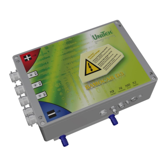
M A N U A L
Digital battery - motor controller
BAMOCAR-PG-D3-400/400
BAMOCAR-PG-D3-700/250
BAMOCAR-PG-D3-700/400
for EC servo motor
for AC asynchronous servo motor
Hans-Paul-Kaysser-Straße 1
71397 Leutenbach-Nellmersbach
Tel: 07195 / 92 83 - 0
contact@unitek.eu
www.unitek.eu
Edition / Version
2021/ V2
Advertisement
Table of Contents

Related Manuals for Unitek BAMOCAR-PG-D3-400/400


Summary of Contents for Unitek BAMOCAR-PG-D3-400/400
- Page 1 M A N U A L Digital battery - motor controller BAMOCAR-PG-D3-400/400 BAMOCAR-PG-D3-700/250 BAMOCAR-PG-D3-700/400 for EC servo motor for AC asynchronous servo motor Hans-Paul-Kaysser-Straße 1 Edition / Version 71397 Leutenbach-Nellmersbach 2021/ V2 Tel: 07195 / 92 83 - 0 contact@unitek.eu...
-
Page 2: Table Of Contents
Risks ............................14 1.14 Technical data ..........................15 Mechanical installation ......................18 Important notes ......................... 18 Dimension drawings BAMOCAR-PG-D3-400/400, 700/250, 700/400 ........19 Mounting on mounting rails ....................... 21 Mounting on mounting surface....................21 Electrical installations ......................22 Important notes ......................... 22 Block diagrams ........................... - Page 3 Basic - Information Serial interface RS232 ......................... 39 CAN-BUS ............................. 40 Resolver connection ........................41 4.10 Encoder TTL connection ......................42 4.11 SIN COS 1VSS Connection ......................44 4.12 Rotor position sensor connection with BL tacho ............... 45 Status information ........................46 Status display on the BAMOCAR ....................
-
Page 4: Basic - Information
Page 50 / Temperature table supplemented / renewed 27.04.2021 More products For synchronous motors and asynchronous motors Digital AC servo amplifier (mains up to 480V~) UNITEK DS series / DPC series Digital AC servo amplifier for battery operation UNITEK BAMOBIL-D3 series... -
Page 5: Validity
Device BAMOCAR-PG-D3-700/400, 700/250, 400/400 Vehicles, boats, machinery or plant manufacturers or operators in the industrial User: sector (B2B, second environment) Manufacturer: UNITEK Industry Electronics GmbH Danger to life! High voltage Warning. Important Dangerous electric fields Scope of delivery / in the shipping box: -Unit BAMOCAR- PG-D3-x -Hint for download "Operating Instructions / Manual“... -
Page 6: General Product Information
Basic - Information General product information The digital three-phase servo amplifier BAMOCAR-PG-D3-400/400, 700/250, 700/400 forms a 4-quadrant drive unit together with the motor, driving and braking with energy feedback in both directions of rotation. Depending on the installed parameter set, the amplifier is suitable for EC synchronous motors, AC asynchronous motors or DC motors. -
Page 7: Application/Use/Design/Property
Basic - Information Application/use/design/property Application: In vehicles, boats, machines and plants of all kinds up to a drive power of 100 kW in rough use, especially as 4Q servo drives for: - highly dynamic acceleration and braking processes, - large control ranges, - high efficiency, - small motor dimensions, - smooth, quiet running and... - Page 8 Basic - Information Features: Battery connection 12 V= / 700 V= (DC mains, observe restrictions). ✓ Independent auxiliary voltage connection 24 V= or 12 V= ✓ Digital interfaces RS232, CAN-BUS (further option) ✓ Analogue inputs, programmable differential inputs ✓ Digital inputs and outputs, programmable, opto-decoupled ✓...
-
Page 9: Safety Regulations
Basic - Information Safety regulations Electronic devices are fundamentally not fail-safe! Attention high voltage DC > 800 V Danger of shock! / Danger to life! DC link discharge time > 4 min. This MANUAL must be carefully read and understood by qualified personnel before installation or commissioning. - Page 10 Basic - Information The user must prepare a hazard analysis for his machine, vehicle or plant. The user must ensure: - that after a failure of the unit, - in case of operating errors, - in case of failure of the regulation and control unit, etc. the drive is guided into a safe operating state.
-
Page 11: Commissioning
Basic - Information Commissioning The servo amplifiers BAMOCAR-PG-D3-400/400, 700/250, 700/400 are components of electronic drive technology. They are only functional in connection with an electrical consumer (e.g. motor). The use is limited to commercial applications. In the case of installation in vehicles, boats, machines and systems, the start of the intended operation of the device is prohibited until it has been determined that the machine, system or vehicle complies with the provisions of the EC Machinery Directive 2006/42/EC and the EMC Directive 2004/108/EC. -
Page 12: Details Of The Safety Instructions
Basic - Information 1.10 Details of the safety instructions Machinery Directive The vehicle, machine or plant manufacturer must prepare a hazard analysis for his product. He must ensure that no unforeseeable movements can lead to personal injury or damage to property. Qualified staff Hardware Qualified personnel are characterised by education and training for the use of electronic drive... -
Page 13: Intended Use
Basic - Information 1.11 Intended use The devices are intended as components for controlling EC synchronous motors and AC asynchronous motors in vehicles, boats, machines or systems. Deviating applications require the approval of the manufacturer. The unit protection class is IP65 (option IP69K). Installation is only permitted in vehicles, boats, machines or systems. -
Page 14: Regulations And Guidelines
Basic - Information 1.12 Regulations and guidelines The units and the associated components must be installed and connected in accordance with the local legal and technical regulations: EC Directive 2004/108/EC, 2006/95/EC, 2006/42/EC, 2002/96/EC EC standards EN60204-1, EN292, EN 50178, EN60439-1, EN61800-3, ECE-R100 International Standards ISO 6469, ISO 26262, ISO 16750, ISO 20653, ISO 12100 IEC/UL... -
Page 15: Risks
Basic - Information 1.13 Risks The manufacturer endeavours to reduce the residual risks emanating from the device as far as possible through design, electrical and software measures. Following known residual risks from drive technology must be taken into account in the risk assessment of machines, vehicles and systems. -
Page 16: Technical Data
Basic - Information 1.14 Technical data Version for three-phase motors Data BAMOCAR Dim. 400-400 700-250 700-400 12 V= .. 24 V = ±10 % /peak 4A (2 A) Auxiliary voltage connection Residual ripple <10 % (self-healing fuse) Supply voltage 12 to. max. 400 12 to max. - Page 17 Basic - Information Environmental conditions Protection class IP 65 (option IP69K) Standards EN60204, ISO 16750, EN61800, IEC60146 Overvoltage 400 V and 700 V DC +10 % Operating temperature range -30 to +85 °C Storage, transport -30 °C to +80 °C EN60721 Installation height ≤...
- Page 18 Basic - Information Current reduction (torque reduction) Only with air cooler Permissible current limit depending on the installation height (not automatic, but must be observed by the user). For air cooler Permissible current limit depending on the ambient temperature. For liquid coolers Permissible current limit depending on to the coolant temperature.
-
Page 19: Mechanical Installation
Mechanical installation 2 Mechanical installation Important notes Check the unit for mechanical damage. Only install faultless units. Mounting only in de-energised state. Disconnect the positive and negative battery terminals, disconnect the DC mains. Assembly only by trained specialist personnel. The installation position is arbitrary for units with liquid cooler. If the heat dissipation is too low, the unit switches off via its thermal monitoring. -
Page 20: Dimension Drawings Bamocar-Pg-D3-400/400, 700/250, 700/400
Mechanical installation Dimension drawings BAMOCAR-PG-D3-400/400, 700/250, 700/400 Standard version (4 connectors fitted) Version: 2021 / V2 Page: 19 BAMOCAR-PG-D3-700/250, 400... - Page 21 Mechanical installation Power connection: Screws for power connections: Allen key M10 x 20 / Max. tightening torque 20 Nm PG cable entry metal M25 x 1.5 With umbrella insert Cable diameter max. 21 mm Recommended cable glands: Lapp-SKINTOP-MS-x Pflitsch-blueglobe TRI Liquid cooler: Cooling medium down to -40 degrees (water + glycol) Hose connection:...
-
Page 22: Mounting On Mounting Rails
Mechanical installation Mounting on mounting rails 4 x M5x20 bolt Support rail and mounting surface must be provided by the customer Mounting on mounting surface Mounting screws: M5 x 40 Spacer rollers: 10 x 20 inside 6.5 Version: 2021 / V2 Page: 21 BAMOCAR-PG-D3-700/250, 400... -
Page 23: Electrical Installations
Electrical installations 3 Electrical installations Important notes The connection instructions are binding in their assignment of the connections to the plug numbers or terminal numbers! All further information on this is non-binding. The input and output lines can be changed and supplemented taking into account the electrical regulations and guidelines. -
Page 24: Block Diagrams
Electrical installations Block diagrams Round plug 19pol M16 Output 4 Version: 2021 / V2 Page: 23 BAMOCAR-PG-D3-700/250, 400... - Page 25 Electrical installations Opto-Driver Version: 2021 / V2 Page: 24 BAMOCAR-PG-D3-700/250, 400...
-
Page 26: Connection Overview
Electrical installations Connection overview Version: 2021 / V2 Page: 25 BAMOCAR-PG-D3-700/250, 400... -
Page 27: Emc
Electrical installations The units comply with the EC Directive 2004/108/EC in the standards EN61800-3 under the following installation and test conditions Mounting: Unit is conductively mounted on a blank mounting plate 500 x 500 x 5 mm. Mounting plate connected to earth via 10 mm². Motor housing connected to earth via 10 mm². - Page 28 Electrical installations Motor connection: Motor cable shielded, flat earth contact When installed in machines and systems, the inclusion of the The use of the appliance for the intended purpose is prohibited for as long as the appliance is in use, until it has been established that the machine or system complies with the provisions of the EC Machinery Directive 2006/42/EC.
-
Page 29: Connector Overview
Electrical installations Connector overview Plugs are not included in the scope of delivery. Display X7 F Pressure equalisation RS232 eedback Valve Inputs/Outputs Parameter Encoder Status error Connector X1 Control inputs/outputs brown Ready for operation pink GND24 Auxiliary voltage 0 yellow +24 V Auxiliary voltage + green... - Page 30 Electrical installations Connector X10 RS232 brown C/P (CTS) white blue V+ (RTS) black V+ (DTR) grey pink Unit View of connector pins Connection plug: Binder 79-3464-52-06 Cable view on solder side Connector X7 Connector X7 Connector X7 Connector X7 Encoder plug Resolver Encoder plug INC-TTL Encoder plug SIN/COS Encoder plug BL...
-
Page 31: Auxiliary Voltage Connection
Electrical installations Auxiliary voltage connection Mains potential-free auxiliary DC V= (4 A) to +24 V= (2 A) ±10 %. Observe the type plate! The auxiliary voltage has • Galvanic connection to the logic voltage • Galvanic protective separation from all internal supply voltages and from the housing. •... -
Page 32: Power Connections
Electrical installations Power connections PG cable gland Metal M25 x 1.5 with shield contact Connection - battery positive pole Connection - Motor W Connection - Motor V Connection-- Motor U Connection - battery negative pole Connection cable maximum 50 mm2 Structure: Only use cables with shield layer! Connection example:... -
Page 33: Battery Connection
Electrical installations Battery connection DC link capacitor C-ZW at 400 V 320 µF at 700 V 320 µF Discharge resistance R-ZW: 50 kΩ Series resistor RV approx. 40 Ω, 50 W Charging current via K2: < 20 A Attention: Enable (RUN) only after the main contactor K1 has been switched. -
Page 34: Motor Power Connection
Electrical installations Motor power connection For synchronous motors (brushless DC motors, EC motors) and AC servo motors with feedback encoder. Follow-up Cable designation Motor cable 3 cores + protective earth Motor phases single shielded, for 1000 V= Connection terminal XB:2 XB:3 XB:4 Shield capacitance 150 pF/m... -
Page 35: Control Connections
Control ports 4 Control ports Digital inputs Input voltage ON level +10.. +30 V OFF level < +6 V Input current Max. 7.5 mA Nominal +24 V/6 mA voltage/current Reference mass GNDE (X1:K) The enable input (FRG/RUN) and the input for rotating field enable (RFE) are permanently assigned and cannot be programmed. -
Page 36: Safety Input Rfe (Rotating Field - Enable) / Stop Category 0
Control ports Safety input RFE (rotating field - enable) / stop category 0 When the input of the release or the rotating field release is switched off the drive is torque-free. Without mechanical brake or lock the drive may fall through or move The motor cables are not voltage-free. -
Page 37: Digital Outputs (0Pen Emitter)
Control ports Digital outputs (Open emitter) Output voltage ON level +12.. +24 V= OFF level < 1 V= Output current Output current max. 2 A, 1s Reference voltage +24 V (X1:D) Reference mass GNDE (X1:K) Output Connection Function Status Parameter BTB/RDY X1:A Ready for operation... -
Page 38: Signalling Contact Ready For Operation (Solid State Relay) / Ready Btb / Rdy
Control ports Signalling contact Ready for operation (solid state relay) / Ready BTB / RDY Hardware safety circuit with solid state relay contact. Software: Message Signal Parameter Status RDY (0x40 Bit 14) Ready for operation BTB = logical 1 In the event of a fault, this safety circuit is disconnected by the relay and the RDY status is set to 0. Other control units (e.g. -
Page 39: Analogue Inputs ±10 V
Control ports Analogue inputs ±10 V Entrance Connection Basic function Voltage Status Parameter AIN1+, AIN1- X1:H, X1:J Speed setpoint ± 10 V prog. AIN2+, AIN2- X1:P, X1:R Current limit ± 10 V prog. 2. speed setpoint Properties Differential input AIN1+ / AIN1- AIN2+ / AIN2- Input resistance 70 kΩ... -
Page 40: Serial Interface Rs232
The serial interface is galvanically connected to the device zero (GND/AGND). Connection between (round plug X10) and the serial BAMOCAR-PG-D3-400/400, 700/250, 700/400 interface (COMx) on the PC only with a shielded null modem cable. Only plug in the cable when the power is off. -
Page 41: Can-Bus
Control ports CAN-BUS The CAN-BUS is the digital connection to the CNC control. Optimum conditions with CNC controls and CAN components from LABOD electronic or CAN Open. Programming and operation via control panel with CAN-BUS. Interface according to ISO 11898. For setting and programming, see NDrive and CAN Manual. -
Page 42: Resolver Connection
Control ports Resolver connection Rundstecker Stecker X7 round connector Only for BAMOCAR-PG-D3-RS Connector x7 Motor-Stecker Motor-Connector The resolver is an absolute measuring system for one Resolver motor revolution. REF1 REF1 REF1 It is robust and insensitive to high engine temperatures. REF2 REF2 The design corresponds to a rotating transformer. -
Page 43: Encoder Ttl Connection
Control ports 4.10 Encoder TTL connection Only for BAMOCAR-PG-D3-IN Rundstecker Stecker X7 round connector Connector x7 VCC +5V TTL incremental encoder (encoder) VCC +5V with 2 counting tracks and one zero track plus 3 rotor position marks. Counting tracks with or without push-pull output. - Page 44 Control ports Adapter for INC encoders with A, B, N channels without push-pull signals The device input for the incremental counting signals requires the push-pull counting pulses for reliable detection. In many simple applications, encoders without push- pull signals (e.g. bearing encoders) are used with different supply voltages.
-
Page 45: Sin Cos 1Vss Connection
Control ports 4.11 SIN COS 1V Connection Only for BAMOCAR-PG-D3-SC Incremental encoder with 2 analogue sinusoidal Counting lanes and one zero lane plus 2 commutation tracks. Differential signals 1 V Maximum counting frequency 500 kHz. The incremental encoder is galvanically connected to the device zero (GND) connected. -
Page 46: Rotor Position Sensor Connection With Bl Tacho
Control ports 4.12 Rotor position sensor connection with BL tacho Only for BAMOCAR-PG-D3-BL 3 rotor position sensor signals (Hall sensors) for commutation. With or without brushless tacho- generator. The rotor position sensor is galvanically connected to the device zero (GND). Supply voltage 15 V from servo. -
Page 47: Status Information
Status information 5 Status information In the "Normal" state, the green 7-segment display plus decimal point lights up as an operating indicator (status display). In the "Error" state, the red error LED lights up and the green 7-segment display indicates the error number. -
Page 48: Status Information - Error
Status information Status information - Error In the "Error" state, the red error LED "FAULT" lights up and the green 7-segment display indicates the error number. Display Error Meaning: Address: on the in NDrive: RegID 0x8F servo: NOREPLY-No RS RS232 interface not plugged in or disturbed. BADPARAS Parameter damaged Bit 0... -
Page 49: Status Information - Warnings
Status information Status information - Warnings "Warning" In the state, the red error LED flashes and the green 7-segment display alternately shows the status and the warning number. Display Warnings Meaning: Address: on the in NDrive: RegID 0x8FH servo: WARNING_0 Device detection inconsistent Bit 16 ILLEGAL STATUS... -
Page 50: Measured Values
Measured values 6 Measured values DC link DC BUS voltage, battery voltage (400 V and 700 V) BAMOCAR 400V 700V DC-BUS Parameter DC BUS DC-BUS Parameter DC BUS voltage 0xEB voltage 0xEB Maximum voltage 460 V 25300 800 V 25200 Overvoltage cut-off 440 V 24200... -
Page 51: Output Stages - Temperature
Measured values 6.2 Power stages - temperature Sensor: 3x NTC (in IGBT) . [0x4A] 32000 °C 28480 31000 °C 28179 °C 27851 30000 °C 27497 °C 27114 29000 °C 26702 28000 °C 26261 °C 25792 27000 °C 25296 26000 °C 24775 °C 24232... -
Page 52: Warranty
UniTek makes no warranty as to the suitability of the unit for any particular application. UniTek shall be liable for defects in the delivery, including the absence of warranted characteristics, only in such a way that, if the goods are returned to the manufacturer's works, they will be repaired free of charge or, if necessary, replaced.
Need help?
Do you have a question about the BAMOCAR-PG-D3-400/400 and is the answer not in the manual?
Questions and answers