
Related Manuals for Unitek BAMO A1


Summary of Contents for Unitek BAMO A1
- Page 1 MANUAL Batterie - Motor-Controller BAMO A1, A2-x-60 ... 500 for DC-Motors Ausgabe 1108-1...
-
Page 2: Table Of Contents
BAMO A1, A2 60-500A Contents Basical Information Page Safety Advice General Information Application Construction Technical Data Mechanical Installation Dimensions 60, 120, 240 Dimensions 280 Dimensions add. Heatsink 60 … 240 Dimensions add. Heatsink 280 Electrical Installation Connection Overview Power connections... - Page 3 - adher to safety regulations Installation work only when disconnected from all power lines. The devices are archived by the manufacturer with serial number and their test specifications. The EU-guide line 89/336/EWG with the Regulations EN61000-2 and EN61000-4 are observed. BAMO A1, A2 60-500...
-
Page 4: General Information
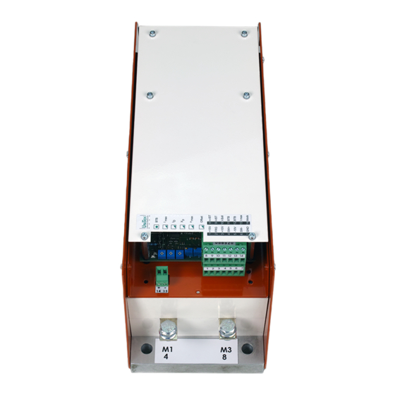
BAMO A1, A2 60-500A General Information The battery motor controller BAMO-Ax-xx forms together with the low voltage DC-motor a propulsion unit distingushed by its high control range. With a DC-motor the current is proportional to the torque and the voltage is proportional to the speed. -
Page 5: Technical Data
36 up to 160V Output voltage 0.8 x U max.30V max. 150V Auxiliary voltage 24V= ±20%, max. 0.5A, waviness <20% Spezifications Type BAMO A1, A2 -x- Steady current max. Peek current max. (5s) El. power max 15.6 23.4 36.4 46.8... - Page 6 BAMO A1, A2 60-500A Dimensions BAMO A1,A2-x-60,120,240 Mounting plate or additional head sink . Size 2...
-
Page 7: Mechanical Installation
2 Mechanical installation Dimensions BAMO A1, A2-x-280, (500) Mounting plate or additional head sink. Size 3 BAMO A1, A2 60-500... - Page 8 BAMO A1, A2 60-500A Additional heat sink type LUKUE - 3,4 (mountig on the BAMO) Size 2 1x addit. heat sink LUKUE 3 (Weight + 3kg) Size 3 1x addit. heat sink LUKUE 4 or 2x LUKUE 3 (Weight + 6kg)
- Page 9 2 Mechanical installation BAMO A1, A2 60-500...
- Page 10 BAMO A1, A2 60-500A BAMO A1, A2 EnableEnable Enable Auxiliary voltage 24V= Comm.value potentiometer Comm.value ± Comm.value± PLC- comm.value Case Battery voltage Speed-act.value Motor connection Current-act.value Current-comm.value signal S1 contact 1 Current limit external Case Overload- signal Notice: Power connection X3:2 (-UB) , X3:10 (+UB) Connection polarity >...
-
Page 11: Electrical Installation
10. Battery voltage Dimensioning at A Battery lines (max. 2m) mm Motor lines Fuse F1 Auxiliary voltage line Fuse F2 Connection lines Caution : with longer lines >>> use a one step strengther cross section ! BAMO A1, A2 60-500... - Page 12 BAMO A1, A2 60-500A Control Connection The connecting advices are for general information and without obligation Notice: - Connecting- and operating instructions - Local regulations - EU-machine regulation pin-No. terminal block X1: 1 up to X1:7 and X2 : 8 up to X2 : 14 Signal lines - Shielded and seperated from power lines.
- Page 13 X1:4 (signal) X1:6 (GND) Int.supply CNC/PLC Comm.value current With A1(1Q) only positiove command value leave out d2 and connection X1:5 is not coated Caution: do not use a command value current between 4 and 20mA BAMO A1, A2 60-500...
- Page 14 BAMO A1, A2 60-500A External current limitation voltage source for external current limit +10V/10mA X1:13 X1:7 Current limit input maximum input voltage +10V input resistance 10 kW internal attenuation with potentiometer I relay contacts: gold- or reed contacts switch S1, contact 2 = OFF (see page 17)
- Page 15 “Blocked” Indication Current demand Outpu X2:14 Normal > +10V Overload < +2V Analogue measuring putputs Function Motor current display Speed display Connection X2:9 , X1:7 X2:8 , X1:7 Value peek current +5.0V Value steady current +2.5V BAMO A1, A2 60-500...
-
Page 16: Power Connections
BAMO A1, A2 60-500A Control connections Function Designation Clamp-Number Voltage 15V/10mA Enable - supply X1:1 Enable +10 bis +30V= Enable - input X1:2 Voltage +10V/10mA Comm.value - supply + X1:3 command value + Comm.value - input + X1:4 Spannung -10V/10mA Comm.value - supply -... - Page 17 Enable X1:3 +10V X1:4 comm. value + (-) Trimmer Function X1:5 -10V X1:6 comm. value - (+) X1:7 Offset X2:8 n-act. value X2:9 I-act. value X2:10 I-comm. value X2:11-12 BTB- contact X2:13 Ext.current limit X2:14 blocked BAMO A1, A2 60-500...
- Page 18 BAMO A1, A2 60-500A Enable Speed controller Current controller Current limit Driving limit Contin.current Driver...
-
Page 19: External Current Limit
Temperature error green glim Error bright Signal outputs Function Designation Clamp-number Speed n-actual value X2:8 Current I-actual value X2:9 Current command value I-comm.value X2:10 blocked +12V/10mA X2:14 Ready for operation -contact BTB/error X2:11 , X2:12 BAMO A1, A2 60-500... -
Page 20: Adjustment
BAMO A1, A2 60-500A Adjustment Advice Adjustment - only by qualified personnel - adhered to safety regulations - notice adjusting sequence Presettings Adjust with Actual value Tacho coarse adjustment R23 Internal/external current limit Switch S1, contact 2 Current regulator P- PI... - Page 21 R-Soll[W] = comm. value voltage/comm. value current Caution: do not use comm. value current between 4 and 20mA With A1x only positve command value Command value integrator Linear-integrator Integration time adjustment with resistor R11 (INT) Resistance (Ohm) BAMO A1, A2 60-500...
- Page 22 BAMO A1, A2 60-500A Actual value - speed BAMO-A1x (1Q) DC- or AC-tachogenerator with rectifer BAMO-A2x (4Q) only DC-tachogenerator Tacho- Connection Jumper J1open Input X1:7 = tacho (GND ) Input X2: 8 = tacho ( Signal) PE-Bolt = shielding Command value input X1: 4 positive >>>...
-
Page 23: Current Limitation
± 0 up to max. 5V 0.12 up to max. 2.5V Caution: for exact torque control: PI-current control switching necessary (default = P-current control) -change from P to PI in current controller (switch S1,Contact1= OFF) BAMO A1, A2 60-500... -
Page 24: Speed Controller Switching
BAMO A1, A2 60-500A Speed controller switching - variable components R9, C4 - amplification potentiometer P3 (X - in case of changing devices >>> take over adjustment values. Defult Setup Values of solded in components P-component = 390kW decrease with R9 (47kW up to 220kW) -
Page 25: Default Setup
± 10V X1:4 Act.value tachometer ± 160V X2:8 (GND X1:7) Armature voltage regulation no actual value connection. Jumper J1 plugged! Default setup for first getting started Function Potentiometer Adjustment Peek current Steady current 100% Amplification Speed BAMO A1, A2 60-500... - Page 26 BAMO A1, A2 60-500A switch off mains Default setup clear failure switch on mains LED BTB glim green overtemperature LED BTB bright green LED "fault" red bright short in motor connection command value 0V enable drive motor speeds up tacho connection...
-
Page 27: Fault Finding
Overvoltage, motorshort or Drive switches to error short to -U LED bright red output stage error Speed cann’t be adjusted with Tacho coarse adjustment R23 wrong trimmer n Jumper J1 wrong, comm.value wrong BAMO A1, A2 60-500... - Page 28 BAMO A1, A2 60-500A Time axis Enable on Motor stands still with torque comm.value positive Motor accelerates comm.value 0V Motor deccelerates comm.value negative Motor accelerates comm.value positive Motor deccelerates and accelerates Speed constant Motor runs with load current Motor deccelerates, device is locked Enable off after 5sec.
-
Page 29: Protocol
Steady currnet Position Amplification Position Speed Position Zero point Offset Position Measuring values Motor voltage max. [V=] Tacho voltage max. [V=] Motor current peek [A=] steady [A=] Motor data Producer Type Series-No. Motor voltage Motor current BAMO A1, A2 60-500... - Page 30 UNITEK. For products returned to UNITEK for warranty service, the Buyer shall prepay shipping charges to UNITEK and UNITEK shall pay shipping charges to return the product to the Buyer. However, the Buyer shall pay all shipping charges, duties, and taxes for products returned to UNITEK from another country.
Need help?
Do you have a question about the BAMO A1 and is the answer not in the manual?
Questions and answers