
Related Manuals for Unitek BAMOCAR-D3


Summary of Contents for Unitek BAMOCAR-D3
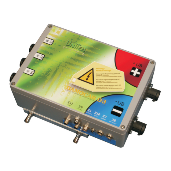
- Page 1 MANUAL Digital Battery-Motor-Controller BAMOCAR-D3 EC Servo Motors AC Induction Motors DC-Servo Motors...
- Page 2 Contents Part 1 Hardware page Basis-information Safety instruction General Application Construction Technical data 9,10 Mmechanical installation Important instructions Dimension BAMOCAR-D3 12,13 Assembly Electrical installation Important instructions Block diagram 16,17 Connection diagram Connectors 20-22 Battery connection Power supply, brake Motor connection...
- Page 3 Basic Information...
- Page 4 BAMOCAR D3 Electronic devices are never fail-safe. Caution: high voltage DC 900V=. Electric shock hazard! Danger to personnel! DC-bus discharge - time >4min This manual must be carefully read and understood by the professional prior to installation or start-up. Consult the manufacturer or the dealer if anything is unclear. Faulty installation can lead to destruction of the devices.
- Page 5 Technical Data The user has to ensure : That the drive will be led to a safe operating condition, after an equipment failure -due to malfunction of controlling or regulating unit Machines, equipments and vehicles are to be further provided with equipment independent monitoring and safety devices.
- Page 6 BAMOCAR D3 Attention nformation...
- Page 7 Technical Data Application in Machines, equipments, vehicles of all types up to drive capacity of 140 kw especially as 4q-servo drives -in case of highly dynamic acceleration and braking processes. -in case of large control areas -in case of high efficiency -in case of small motor dimensions -in case of constant , silent operation for rpm control, torque control or combined torque- rpm control with or without superimposed...
- Page 8 BAMOCAR D3 Construction : Compact equipment Acc. to VDE-DIN-EG- standards. IP 65 protection against accidental contact with power connections. Power electronics for ( S1 operation ) 125 A, 200 A,(peak 250A, 400A) Input power range nom. 12 to 700 V = Liquid cooling ( special construction air cooling) Unified digital controller electronics) Independent 12/ 24V DC chopper power unit for auxiliary power.
- Page 9 ± 10% / 4a (2a) Auxiliary supply Ripple voltage <10%, self-resttable fuse Data dim. 125/250 200/400 125/250 200/400 BAMOCAR-D3-400- (700)- Rated supply voltage 24 bis max .400 24 bis max .700 Rated output voltage V~eff to 3x260 to 3x450 Continue current rms Peak current Dissipation max.
- Page 10 £ 1000m ü.nn 100%, >1000m with power derating Site altitude 2%/100m Cooling liquid cooler max 65 c , 12 l/min , precher max 1,3 bar Mounting position equal Program Type Software-version BAMOCAR-D3(D2)-xx-rs resolver BAMOCAR-D3-(D2)xx-in encoder-ttl BAMOCAR-D3-(D2)xx-sc encoder-sincos 1vss BAMOCAR-D3-(D2)xx-bl rotorlage+bl-tacho dc-tacho, BAMOCAR xx-DC...
- Page 11 Mechanical Installation Important instruction Check the equipment for mechanical damage Install only defect-free equipments Assembly only in non-energized condition Disconnect the positive and negative terminals of the battery, disconnect DC supply. Assembly only by trained personnel The installation position is discretionary in case of equipments with liquid cooling.
- Page 12 BAMOCAR D3 Screw for hex key BAMOCAR...
- Page 13 Mechanical Installation Liquid cooler Connection hose connection metall 13mm inlet temperature 50 grad c flow max 12l/min pressure max 1,3 bar...
- Page 14 BAMOCAR D3...
- Page 15 Electrical Installation Important instructions The connection instructions are classified according to the connector numbers respectively and are mandatory. All further instructions hereto are non-binding. The input and output lines can be modified and supplemented, under consideration of electrical regulations and guidelines Regulations to be observed are Connection and operational instruction Local regulations...
- Page 16 BAMOCAR D3...
- Page 17 Electrical Installation...
- Page 18 BAMOCAR D3...
- Page 19 Electrical Installation...
- Page 20 BAMOCAR D3 Connectors Connector X9, X9.1 Connector X1 IN / Output CAN-BUS Connector X 10 RS232 Connector X11 Brake...
- Page 21 Electrical Installation Feedback- connector X7 Connector X8 Output / 2 Input ENC-TTL At all connectors: View the plug on solder-crimp side.
- Page 22 BAMOCAR D3 Power connectors 1000V / 400A Connector socket plus Pfisterer p1 (350 205-301 (-302)) Connector socket minus Pfisterer p1 (350 205-301) Motor connector socket Pfisterer p1 (350 205-301) Connector plug plus Pfisterer connector straight p1 (350205-002..) or connector angle p1 (350205-102) Connector plug minus Pfisterer...
- Page 23 Electrical Installation Connection to the battery Attention: Warning The max. supply voltage U + 400 (700) must not be exceeded at any time (not even for short intervals)! Danger of damage! F1 = safety fuse Connection has no protection against reverse polarity. If the polarity of the connection is wrong, the device will be destroyed Type -125/250...
- Page 24 BAMOCAR D3 Auxiliary power connection Mains independent Auxiliary dc voltage 12 V = up to 24 V = +/- 10 % / 4 up to 2 A The Auxiliary voltage has - galvanic connection to logic voltage - internal self healing fuse - emc filter - external fuse only for line protection Input voltage...
- Page 25 Elektrical Installation Motor – power connection Use only UNITEK approved, electronically commutated synchronous motors ( brushless dc motors, ec motors) with resolver or incremental encoder . Refer Appendix A ( motor specific connection and parameter guidelines) Connection sequence Cable indication...
- Page 26 BAMOCAR D3...
- Page 27 Electrical Installation Digital inputs Opto-input The enable input- (FRG/RUN) and the input for rotary field release ( RFE) are pre-fixed and cannot be programmed. Without FRG/RUN release , the servo is electronically blocked ( no pwm pulses). Without rotary field release RFE, the rotary field of the output stage is additionally blocked electronically.
- Page 28 BAMOCAR D3 Safety – input RFE ( rotary field – release) Attention : The drive is momentum-free , in case of disabled input release or rotary field release . If there are no mechanical brakes or blocks, the drive can stop or be in motion , the motor cables are not potential-free.
- Page 29 Electrical Installation Digital logic- outputs ( open- emitter) Logic outputs 1 to 3 are for laid out for 12/ 24 V and 1 A . Short time 2 A. Output voltage On-level max. +24V Off-level <1V Output current nom. 1A Output current max.
- Page 30 BAMOCAR D3 Analog inputs +/- 10V Inputs Terminal Basic function Voltage Status Parameter Characteristics Differential input Ain1+/Ain1- Ain2+/Ain2- The direction of rotation of the motor can be changed by reversing the +/- polarity at the differential input, by a logic- input or by programming . In case of digital reference value ( RS 232, x bus), analog input Ain 1 can be programmed as external rpm limit and the Analog input Ain 2 can be programmed as external analog current limit.
- Page 31 - zero (GND) . The software is described in the software-manual DS NDrive. Connection between the BAMOCAR-D3 ( d-connector X10 ) and the serial interface only through a null modem-cable. Do not use null modem-link cable! Cable to be plugged in only in de-energized condition.
- Page 32 BAMOCAR D3 CAN-BUS The CAN-BUS input is galvanically separated. The power supply is from the intern DC/DC CAN-BUS cable Use a shielded bus conductor with a low shielding capacity. Signal plus GND (+supply). D-connector with a metal or metallized housing. LiYCY 4x0.25+shield. Designation Cable colour...
- Page 33 Elektrical Installation Resolver - connection. Applicable only for BAMOCAR D3 xx-RS...
- Page 34 BAMOCAR D3 Encoder TTL Anschluß only BAMOCAR-D3-IN...
- Page 35 Electrical Installation SIN / COS 1Vss Anschluss only BAMOCAR-D3-xx-SC...
- Page 36 BAMOCAR D3 Rotor sensor Anschluss with bl-tacho only BAMOCAR-D3- xx-bl...
- Page 37 Electrical Installation X8 TTL- Encoder output or input ( 2) The D- connector X8 will be operated as input or output( default). Output X8 pin c not used or connected with GND. Input X8 pin c connected with + 5 v ( x8: a) Attention X8 as input Connector X8...
- Page 38 BAMOCAR D3 X8 as TTL-Encoder output Sensor signals( feedback ) from the motors will be given as ttl – encoder signals for cnc control at d connector X8. Encoder output is potentially isolated . Power is supplied through the senor cable from the cnc/ sps control. Power supply + 5 V +/ - 0.2 Volts Output signal complies with RS 485.
- Page 39 Electrical Installation Light indications on BAMOCAR-D3 In case of „ normal“ condition , the green 7 segment indicator and decimal points glow indicating operational condition ( status- indication) In case of „ fault“ the red led „ FAULT“ glows and the 7 segment indicator indicates the fault number.
- Page 40 BAMOCAR D3 Fault indication on BAMOCAR-D3 The red led“FAULT“ lights up and the fault number will be indicated by the green 7 segment display. List of faults Display at Error message Meaning address on the NDrive BAMOCAR Ox8f BADPARAS Parameter error...
- Page 41 Electrical Installation Fault –warning indications on BAMOCAR-D3 In case of „warning“, the red FAULT led blinks and the 7 segment display alternatively indicates the status and the warning number. List warning messages Display at Error message Meaning address on the NDrive...
- Page 42 24813 without power voltage standardization 36,49 parameter 0xa5 = 36,49 x DC link voltage Current actual Calibration rated current Peak current BAMOCAR-D3 I-100% i-device dc blocked maximum value +/- 11bit Aeff 400 (700) -250/150 400 (700) -400/250 Basic reference values are stored in the parameter set.
- Page 43 Electrical Installation Stage-temperature IGBT temperature parameter 0x4a maximal +83 24000 (FW>400) 32000 30000 28000 26000 24000 22000 20000 18000 16000 Endstufen- Temperatur ( C) BAMOCAR Stage- Temperature ( C) Air-temperature 14000 13000 12000 11000 10000 9000 Luft- Temperatur ( C) Air- Temperature ( C)
- Page 44 BAMOCAR D3 DC-Link voltage 30000 25000 20000 15000 10000 5000 BAMOCAR 400V BAMOCAR 700V Zwischenkreis-Spannung [ V ] DC-Link voltage Settings for BAMOCAR 400/400 DC-BUS max (0xa5H) for max voltage 440V = 23670 = 72% for max voltage 400V = 21520 = 66% DC-BUS min (0xa5L) for undervoltage 320V = 17210 = 52%...
- Page 45 Electrical Installation...
- Page 46 In case of defects in delivery, including non-availability of assured features, the liability of UNITEK is only free of charge rectification, if sent to the manufacturer’s works or would be replaced if necessary. This liability of defects is void, when repair and maintenance is done in an improper way by...
Need help?
Do you have a question about the BAMOCAR-D3 and is the answer not in the manual?
Questions and answers