Table of Contents
Advertisement
Quick Links
Advertisement
Table of Contents

Related Manuals for gefran KFM LD


Summary of Contents for gefran KFM LD
- Page 1 Door Drive KFM LD ..Instruction manual...
-
Page 2: Information About This Manual
Thank you for choosing this Gefran product. We will be glad to receive any possible information which could help us improving this manual. The e-mail address is the following: info@sieiareg.de... -
Page 3: Table Of Contents
1.5. Personal protective equipment .........................7 1.6. Disposal of the door drive ........................8 Description ............................9 2.1. KFM LD door drive, complete / Integrated ....................9 2.2. KFM LD door drive, separated .......................10 2.3. Connection – Motor side ........................11 2.4. Connection options complete and separated ..................12 2.5. - Page 4 Connecting .............................25 4.3.1. X2 for trigger signals with pin assignments ......................25 4.3.2. Connection of the KFM LD door drive to conventional 24V logic level ..............26 4.3.3. CAN bus connection (Not implemented in KFM LD) ....................27 4.3.4. Power supply - KFM LD control complete and separated ..................28 Commissioning ..........................29...
-
Page 5: Safety
Safety information and instructions required by law must be displayed to users in such a way that they are clearly visible. • A requirement for safe handling and non-disruptive operation of this product is knowledge of the fundamen- tal safety regulations. KFM LD • Instruction manual... -
Page 6: Obligations Of The Operating Company And Installation Firm
Comply with the commissioning instructions, the installation description as well as the required inspection and maintenance work • Do not make unnecessary runs; bear in mind that the elevator is a means of transport and not a toy. KFM LD • Instruction manual... -
Page 7: Personal Protective Equipment
Ear protection • Flying parts • Flying particles Eye injury Eye protection • Laser beams Loss of sight/ blinding • Optical beams • Electrical Voltage Electric shock Enable source of energy Tab. 1 Warning pictograms KFM LD • Instruction manual... -
Page 8: Disposal Of The Door Drive
By collecting the disused equipment separately, it can be recycled, treated or disposed of in an environmentally friendly manner, thus helping to prevent the environment and public health from being affected negatively and enabling reuse and/or recycling of the materials forming the same equipment. KFM LD • Instruction manual... -
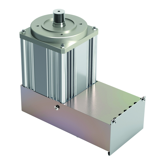
Page 9: Description
2. Description 2.1. KFM LD door drive, complete / Integrated Fig. 1 Item Designation Item Designation Drive bearing Connection of motor + controller V-groove belt on motor side Tightening screw Door drive motor Header Inspection switch Toothed belt on coupler side... -
Page 10: Kfm Ld Door Drive, Separated
2.2. KFM LD door drive, separated In the KFM LD door drive there is an insulation paper over the electronic parts to protect the technician from contact with live parts during commissioning. For this reason, the insulating paper must not be removed and after... -
Page 11: Connection - Motor Side
Item Designation Item Designation Fastening - impulses / temp. line Connection for Pulse encoder Fastening - motor line Housing of control device Motor connection Inspection switch Connection for Temperature sensor Tab.5 Connectors of KFM LD KFM LD • Instruction manual... -
Page 12: Connection Options Complete And Separated
TUL (default) Inspection approval Tab.7 Connector X2 X3 RM3.81 Output Signals TSU (default) TSO (default) >150N (default) n.c. Tab.8 Connector X3 X3 RM3.81 Output Assignment Connection +24V X2:1 X3:4 X2:2 X2:2 n.c. Tab.9 Connector X4 KFM LD • Instruction manual... -
Page 13: Control Device Kfm Ld Complete
Connected X5:1 CAN-L CAN-H Tab.10 Connector X5 X2 RM3.81 Input Assignment L1 (230V/50Hz) Tab.11 Connector X7 2.5. Control device KFM LD complete F1/F3 F1/F3 H1 - 4 H1 - 4 Fig. 6 X7 F1 F3 X6 H1...H4 Fig. 7 Item... -
Page 14: Connection Options
5. In the CAN connection X5, pins 1and 2 interconnected. The CAN signals are simultaneously on the connec- tions X5 and X1. Connection information, program updates and further details from the manufacturer are available from SIEI-AR- EG GmbH. KFM LD • Instruction manual... -
Page 15: General Description
2.6. General description The contents of these instructions refer to the current software version. The KFM LD door drive is intended standard for the drive of the different car door, with unknown ratios. It simultaneously replaces control device and drive of types F2/1 and F5 during replacement and conversion work. -
Page 16: Drive Functions
The generation of the profile for widening cam operation can be switched off via E@syDrives. The running characteristic curve of the KFM LD drive is not jerk-limited. (Thus, the speed curve is not rounded – see Fig. 8). All parameters of the running characteristic curve for opening, closing, nudging and re-opening can be set independent of one another. -
Page 17: Running Characteristic Curve Kfm Ld Not Jerk-Limited
Fig. 8 2.9.4. Running characteristic curve KFM LD not jerk-limited. When a door end position is reached, this is recognised automatically by the drive and a corresponding end position signal (TSU / TSO) is sent to the elevator control. The door drive now presses the door against the end position with an adjustable torque as long as the corresponding trigger signal (TO, TU, TUL) is applied. -
Page 18: Stop Function
Slip opening is tripped under the following conditions: The TO and TUL trigger signals (nudging) are applied simultaneously, TU is inactive and the slip function on the control device of the KFM LD door drive is activated. (Activated by entering the % value.) The door travels to the door position set for slip opening (TSSOE). -
Page 19: Trigger Signal From The Elevator Control - Trigger With 24V Logic Signals
The trigger signals are processed by the control electronics depending on the state, i.e., the corresponding action is only performed while the respective signal is applied. If all the trigger signals are inactive, the KFM LD door drive switches to a state without torque. -
Page 20: Error Diagnosis And Display Options
2.9.16. Error diagnosis and display options The KFM LD door drive has an event stack that stores errors and warnings in non-volatile form, for example, overtemperature of the heat sinks, etc. The error stack can only be read out with one of the service programs. -
Page 21: Technology
Product family EN81, EN 12015 and EN 12016 V-grove washer Diameter 23,5 mm, effective for Belt 26 mm with 8 groves Approval CE, CCC (optional: UL CSA) KFM LD door drive CV Compact version 782301-011 KFM LD door drive SV Separate version 782306-006 Separate version Motor 871035-003 Tab. -
Page 22: Kfm Ld Dimensions, Complete
3.2. KFM LD dimensions, complete Fig. 9 For the V-groove washer, the effective diameter is 26 mm due to the thickness of the V-groove belt. The driving belt movement is 81.68 mm per revolution. 3.3. KFM LD dimensions, separated Fig. 10 Fig. -
Page 23: Installation
11. Connect motor and controllers according to instructions and the terminal connecting plan. See Chap. 4.2 on page 25. Note ! After completing commissioning, the controller housing has to be closed with the cover. This is important for both versions KFM LD • Instruction manual... -
Page 24: Adjusting The Belt Tension
The ambient noises in the measuring range should not be excessively loud. The measurement result can be opti- mised somewhat by adjusting the volume at the microphone input. Important KFM LD • Instruction manual... -
Page 25: Replacing F2/1, F5, F9 With Kfm Ld
Chap. 4.3 on page 25. Note ! With the KFM LD drive, it is possible that the connection lines may need to be lengthened on account of the prior separate ar- rangement of the controller. -
Page 26: Connection Of The Kfm Ld Door Drive To Conventional 24V Logic Level
Fig. 15 4.3.2. Connection of the KFM LD door drive to conventional 24V logic level Accessory cable F2/F3/F5/F9, 6-pin. Accessory cable F9, 4-pin, similar to F3 3-pin Trigger signals +24 V / 0 V Acknowledge signals +24 V / 0 V... -
Page 27: Can Bus Connection (Not Implemented In Kfm Ld)
Via jumper J3, the CAN bus can be terminated on the control electronics with 120 Ω. (Jumper closed → Bus terminated with 120 Ω). The jumper must be closed if the KFM LD door drive forms the last node on the bus and the bus is not connected to any other subassembly. -
Page 28: Power Supply - Kfm Ld Control Complete And Separated
When intervening in the device, observe the warning notices on residual Voltage! Caution SIEI-AREG GmbH supplies the KFM LD only with the connectors X2, X3, X4 and X7. All other connectors and cables must be procured or manufactured by the customer. -
Page 29: Commissioning
• Described in the following are the processes for commissioning. • Commissioning is carried out the button T1, the LED’s as well as the setting of the switches S1 an S2. Fig. 19 Fig. 20 KFM LD • Instruction manual... -
Page 30: Learning The Gear Ratio (Aipm)
Fig. 21 5.2. Learning the gear ratio (aipm) The KFM LD drive is designed for different car door. For doors with a different drive gear ratio. The gear ratio (aipm in impulses per cm) must first be learned by the controller. - Page 31 Block off the area in front of the elevator door accordingly. • Prepare to abort the automatic process with the T1 button or to switch the KFM LD to a voltage-free state. • During the automatic door movement, constantly check the area in front of the elevator door.
- Page 32 Note ! In position 0 of HEX switch S2, no automatic commissioning is possible! A change of switching position S2 does not take effect until after automatic commissioning. KFM LD • Instruction manual...
-
Page 33: Manually With The Service Program
5.4. Manually with the service program Service program: The service programs are software programs for the KFM LD drive. If a PC or laptop is connected to the controller of the drive, the door drive can be set and individually adjusted in a menu-driven manner with the help of the service program. -
Page 34: Error Messages During Automatic Commissioning
The required torque is too high when learning > Door blocked (landing door lock?) the force to open the door. (5 cm before position > Wrong reduction ratio "DoorCLOSED") KFM LD • Instruction manual... -
Page 35: Explanation Of The Led Indicators
LED 1 blinks in an alternating rhythm with LED 2 and LED 3 (1 on, 2 and 3 off); (1 off, 2 and 3 on) Tab. 30 Explanation of the LED indicators Still corresponds to the display from the previous normal door operation (user defined). KFM LD • Instruction manual... -
Page 36: Switch Setting
Replace F5 and F9 Glass door, normal 8.4 J 0.45 m/s 0.3 m/s i = 130 Replace F5 and F9 Glass door, fast 16.8 J 0.65 m/s 0.4 m/s i = 130 Replace F5 and F9 KFM LD • Instruction manual... -
Page 37: Setting Of Switch J3 And Jumper J4
Jumper open → DEFAULT Condition on delivery: On delivery of the drive, the settings of the KFM LD door drive are matched to car doors. aipm gear ratio i = 130 impulses per cm. HEX switch S1 in position 1 HEX switch S2 in position 2 Switch J3 rear No shunting resisto. -
Page 38: Maintenance
Notices for commissioning – replacement The KFM LD control device replaces the F2/1, F5 and F9 control devices. For spare part delivery or replace- ments, the KFM LD control device can not be used together with door motor F2/1, F5 or F9. - Page 40 Fax +33 (0) 478770320 info@gefran.com.cn Fax +55 (0) 1132974012 commercial@gefran.fr comercial@gefran.com.br GEFRAN S.P.A. GEFRAN DRIVES AND MOTION S.R.L. Via Sebina 74 25050 Provaglio d’Iseo (BS) ITALY Via Carducci 24 Ph. +39 030 98881 21040 Gerenzano [VA] ITALY Technical Assistance : Fax +39 030 9839063 Ph.
Need help?
Do you have a question about the KFM LD and is the answer not in the manual?
Questions and answers