Table of Contents
Advertisement
Quick Links
Advertisement
Table of Contents

Subscribe to Our Youtube Channel
Related Manuals for gefran ADV200-SI Series


Summary of Contents for gefran ADV200-SI Series
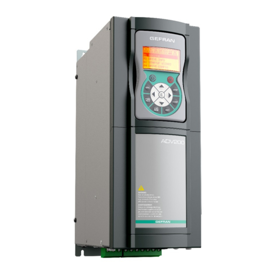
- Page 1 ADV200-…-SI with External safety modules English User manual...
- Page 2 Keep the manual in a safe place and available to engineering and installation personnel during the product functioning period. Gefran spa has the right to modify products, data and dimensions without notice. The data can only be used for the product description and they can not be understood as legally stated properties.
-
Page 3: Table Of Contents
Table of Contents Introduction ............................... 4 Safety modules ............................ 5 Safety Precautions ........................... 6 Symbols used in the manual ....................... 6 Safety Requirements ........................... 6 Installation and use of safety functions ....................7 Wiring and Installation ..........................8 Encoder wiring ............................. 8 STO Wiring ............................ -
Page 4: Introduction
1 Introduction This manual covers the implementation of operational safety functions, as described and specified in EN61800-5.2, EN61508, EN 13849-1. Specifically, the Gefran ADV200-...-SI series drives, which come with internal and external safety modules, support the following safety functions: •... -
Page 5: Safety Modules
1.1 Safety modules The safety modules are certified modules for running various, also complex, safety functions, configurable by using the special software suite that is shipped with them. Main specifications Protection level Housing, IP 20 - Terminal block IP 2X Operating temperature -10 to 55 °C Dimensions (HxWxD) -
Page 6: Safety Precautions
2 Safety Precautions 2.1 Symbols used in the manual Indicates a procedure, condition, or statement that, if not strictly observed, could result in personal injury or death. Indique le mode d’utilisation, la procédure et la condition d’exploitation. Si ces consignes ne sont passtrictement respectées, il y a des risques de blessures corporelles ou de mort. -
Page 7: Installation And Use Of Safety Functions
3 Installation and use of safety functions The installation and use of safety functions calls for several study and execution phases, specifically: 1. Risk analysis; 2. Identification and configuration of machine safety functions; 3. Design, integration and use of components involved in the safety functions; Installation and Wiring of ADV200-xxx-SI 5. -
Page 8: Wiring And Installation
4 Wiring and Installation Running the safety functions requires one or both of the following configurations: • STO (EXP-SFTy-ADV) Safety Interface (*) installed on all drives with the "SI" suffix (e.g., ADV200-…-SI) • Optional Encoder Card installed on the ADV200-…-SI (EXP-DE/EXP-SE) drives. The requirement for one or both would depend on which basic functions are to be used. - Page 9 In any case, the wiring diagram requires an encoder whose signals can be used by both the ADV200 and the safety module. TTL and sin/cos encoders should be wired as specified and illustrated in Figure 2, connecting first to the ADV200 expansion card and then retransmitting the signal (repetition) from the drive to the safety module.
-
Page 10: Sto Wiring
All safety functions that check for risks operate by running the drive-integrated STO function, which disengages the motor from the drive system torque. In addition to implementing the STO function, safety modules can protect the system by applying other means (motor brakes, mechanical blockage, etc.) according to the machine-related function. -
Page 11: Use And Integration
5 Use and Integration 5.1 STO Function The STO function is integrated within the ADV200 drive as an optional. It requires no external modules but the use of a drive from the ADV200 series with the STO safety function integrated (ADV200-….-SI). For additional details about running the ADV200 STO safety function, please see the Safety manual (code 1S5F94, EN). -
Page 12: Sdi Function
5.3 SDI Function The Safe Direction (SDI) function controls motor rotation direction: a properly wired and configured safety module checks that the motor turns in one direction only. Upon detecting that the motor rotates in the reverse direction, the safety module triggers an alarm. Configuration and detection methods related to the condition of reverse rotation are described in the safety module manual. -
Page 13: Sil Levels Provided By Safety Functions
6 SIL levels provided by safety functions The ReeR modules used together with the Gefran AD200-xx-SI drives allow the implementation of the STO, SS1, SDI and SLS safety functions as described in Paragraph §5, providing a SIL3 safety level according to EN 61508 standards and Pl level according to EN13849-1/2 standards when properly designed and used following the recommendations of both manufacturers. - Page 14 Ph. +91 20 6614 6500 Fax +44 (0) 8452 604556 Fax +91 20 6614 6501 sales@gefran.co.uk gefran.india@gefran.in SENSORMATE AG GEFRAN MIDDLE EAST ELEKTRIK VE GEFRAN INC. ELEKTRONIK SAN. VE TIC. LTD. STI Steigweg 8, 8 Lowell Avenue Yesilkoy Mah. Ataturk...
Need help?
Do you have a question about the ADV200-SI Series and is the answer not in the manual?
Questions and answers