
Subscribe to Our Youtube Channel
Related Manuals for Thundercomm Qualcomm Robotics RB5


Summary of Contents for Thundercomm Qualcomm Robotics RB5
- Page 1 Empowering Every IoT Device with Our Technology Qualcomm® Robotics RB5 Development Kit Hardware User Manual Rev. 1.0 Sep 24, 2020 Copyright© 2020 Thundercomm Technology Co., Ltd. All rights reserved.
- Page 2 Robotics RB5 Development Kit Hardware User Manual Revision History Revision Date Description Sep 24, 2020 Initial Release Copyright© 2020 Thundercomm Technology Co., Ltd. All rights reserved.
-
Page 3: Table Of Contents
External Fan connection ........................12 3.14 UART ..............................12 3.15 JTAG (NA) ............................12 3.16 System and user LEDs ........................12 3.17 Expansion Connector ........................13 3.18 Additional Functionality ........................13 Copyright© 2020 Thundercomm Technology Co., Ltd. All rights reserved. - Page 4 5.1.3 I2C............................... 28 5.1.4 HSIC ............................28 5.1.5 Reserved ............................ 28 5.1.6 SD/SPI ............................28 5.1.7 Camera Clocks ........................... 29 5.1.8 USB ............................. 29 Secondary High Speed Connector: HS2 ..................29 Copyright© 2020 Thundercomm Technology Co., Ltd. All rights reserved.
- Page 5 Bluetooth status ........................38 7.2.4 Power Indicator LED ......................... 38 Boot configuration ....................... 39 Mechanical specification ..................... 40 Appendix ..........................43 10.1 Navigation Mezzanine ........................43 10.1.1 Technical specifications ......................43 Copyright© 2020 Thundercomm Technology Co., Ltd. All rights reserved.
- Page 6 Robotics RB5 Development Kit Hardware User Manual 10.1.2 Board views ..........................44 10.2 Machine Communication Mezzanine .................... 45 10.2.1 Technical specifications ......................45 Copyright© 2020 Thundercomm Technology Co., Ltd. All rights reserved.
-
Page 7: Qualcomm ® Robotics Rb5 Development Kit
- and the comprehensive Qualcomm Robotics RB5 Development Kit helps ensure developers have the customization and flexibility they need to make their visions a commercial reality. - Page 8 12V@2.5A adapter with a DC plug, with inner diameter as 1.75mm and outer Power supply diameter as 4.75mm 85mm x 54mm, meeting 96Boards Consumer Edition Standard form dimensions Dimension specifications Copyright© 2020 Thundercomm Technology Co., Ltd. All rights reserved.
-
Page 9: Board Views
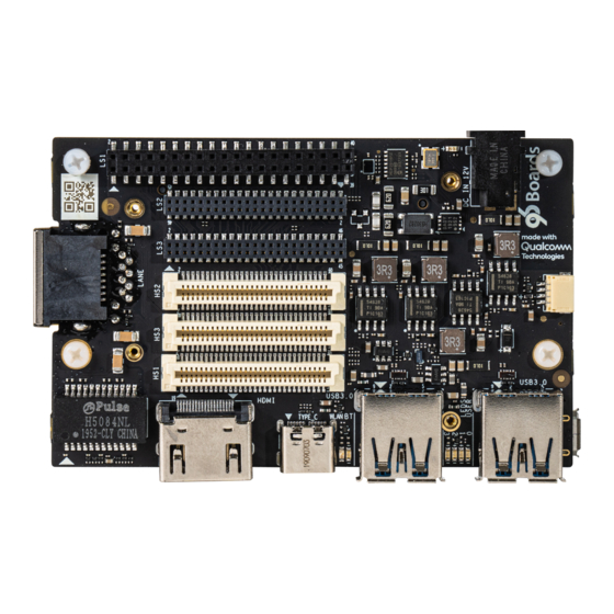
Robotics RB5 Development Kit Hardware User Manual Board views 1.2.1 Top view Copyright© 2020 Thundercomm Technology Co., Ltd. All rights reserved. -
Page 10: Back View
Component Description Qualcomm Universal Peripheral The QUP engine provides a general-purpose data path that supports multiple mini cores, e.g., UART, I2C and SPI Camera Control Interface SPMI System Power Management Interface Copyright© 2020 Thundercomm Technology Co., Ltd. All rights reserved. -
Page 11: Start The Board
2. Turn on SW2 on the Dip Switch#1 (see section 1.2.2, #16) to enable the USB2.0 debug port (see Section 1.2.2, #21). 3. Turn on SW3 on the Dip Switch#1 (see section 1.2.2, #16) to enable the auto power up on (along with power connector). Copyright© 2020 Thundercomm Technology Co., Ltd. All rights reserved. -
Page 12: Qualcomm® Robotics Rb5 Development Kit
8. The board will start the booting process. Login credentials will display on the host PC: qrb5165-rb5 login: root Password: oelinux123 3 Qualcomm® Robotics RB5 Development Kit System Block diagram Block diagram part #1 Copyright© 2020 Thundercomm Technology Co., Ltd. All rights reserved. - Page 13 Robotics RB5 Development Kit Hardware User Manual Block diagram part #2 Copyright© 2020 Thundercomm Technology Co., Ltd. All rights reserved.
-
Page 14: Processor
The UFS flash memory interfaces with QRB5165 over a dedicated UFS PHY bus supporting the UFS 3.0 specification. MicroSD MicroSD slot signals are routed directly to the QRB5165 SDC2 interface. Copyright© 2020 Thundercomm Technology Co., Ltd. All rights reserved. -
Page 15: Wi-Fi/Bt
It is QUP5 I2C interface from SoC. This bridge supports audio as well (meeting the 96Boards requirements for providing audio via HDMI). The RB5 uses a 4 bit I2S2 interface from the QRB5165 for this task. Copyright© 2020 Thundercomm Technology Co., Ltd. All rights reserved. -
Page 16: Mipi-Dsi
4-lane CSI3 camera on high-speed connector HS1 (section1.2.1 #6) and high-speed connector (section1.2.1 #7) 4-lane CSI4 camera on high-speed connector HS3 (section1.2.1 #7) 4-lane CSI5 camera on high-speed connector HS3 (section1.2.1 #7) USB Ports Copyright© 2020 Thundercomm Technology Co., Ltd. All rights reserved. -
Page 17: Usb-Host Ports
A 4-bit (audio out only) I2S channel is routed directly from the QRB5165 SoC I2S interface pins to the DSI-HDMI bridge. 3.9.3 DisplayPort Audio The DisplayPort audio is routed directly from the QRB5165 SoC eDP interface pins to the Type C USB connector. Copyright© 2020 Thundercomm Technology Co., Ltd. All rights reserved. -
Page 18: Dc-Power And Battery Power
3.15 JTAG (NA) 3.16 System and user LEDs RB5 supports seven LEDs on the board. LEDs color and mechanical location on the board are designed based on 96Boards specification. Two activity LEDs Copyright© 2020 Thundercomm Technology Co., Ltd. All rights reserved. -
Page 19: Expansion Connector
RB5 implements a few additional functions as described from Sections 3.17.1 to 3.17.4 3.18.1 Ethernet Connector RB5 has the translation from USB1, a USB HUB and a USB to Gigabit Ethernet controller. RB5 uses an RJ45 (see Section1.2.1, #9) as the physical interface. Copyright© 2020 Thundercomm Technology Co., Ltd. All rights reserved. -
Page 20: Inertial Sensors
Switch 2 – BOOT_CONFIG(2). Switch 3 – BOOT_CONFIG(3) Switch 4 – BOOT_CONFIG(0) 3.18.4 Extra Low Speed Expansion Connector RB5 has 3 extra low-speed expansion connectors. See Section 4 for detail. Copyright© 2020 Thundercomm Technology Co., Ltd. All rights reserved. -
Page 21: Extra High Speed Expansion Connectors
Robotics RB5 Development Kit Hardware User Manual 3.18.5 Extra High Speed Expansion Connectors RB5 has 3 high-speed expansion connector. See Section 5 for detail Copyright© 2020 Thundercomm Technology Co., Ltd. All rights reserved. -
Page 22: Low Speed Expansion Connector
From PM8250 BUCK From on board DCDC RB5 Signal Additional Info PWR_BTN_N PHONE_ON RST_BTN_N Default volume down; SPI0_SCLK QUP17 SPI0_MISO QUP17 SPI0_CS QUP17 SPI0_MOSI QUP17 PCM_FS/I2S0_WS PCM_CLK/I2S0_CLK PCM_DO/I2S0_D1 PCM_DI/I2S_D0 GPIO-B PCM0_MCLK GPIO-D/QUP_A3 QUP1 Copyright© 2020 Thundercomm Technology Co., Ltd. All rights reserved. -
Page 23: Uart
GPIO C/QUP_A1: Connects to GPIO_5 of QRB5165 SoC. GPIO D/QUP_A3: Connects to GPIO_7 of QRB5165 SoC. GPIO E/QUP_A2: Connects to GPIO_6 of QRB5165 SoC. GPIO F: Connects to GPIO_46 of QRB5165 SoC. Copyright© 2020 Thundercomm Technology Co., Ltd. All rights reserved. -
Page 24: Spi
(see Section 1.2.2, #17). This signal is dual purpose, the default purpose is Volume down, and the second purpose is the Reset function which needs the software configure setting. Copyright© 2020 Thundercomm Technology Co., Ltd. All rights reserved. -
Page 25: Power Supplies
Additional Info GPIO_U CAM3_RST_N DMIC_CLK1_LS2 DMIC_DATA1_LS2 GPIO_V I2S1_DATA2/ext codec/CAM0_STROBE_N DMIC_CLK2 DMIC_DATA2 GPIO_W I2S1_DATA3/ext codec/CAM5_RST_N DMIC_CLK3 DMIC_DATA3 PM_GPIO-F PM8250_GPIO3 CCI_I2C_SCL2 CCI_I2C_SDA2 CCI_I2C_SCL3 SPK0_P SPK0_M SPK1_P SPK1_M CCI_I2C_SDA3 PM_GPIO-E PM8250 AMUX1/MDM SKIN THERM Copyright© 2020 Thundercomm Technology Co., Ltd. All rights reserved. -
Page 26: Audio
1 digital mic on development board 3 pairs of DMIC signals are routed to LS 4.2.2 Stereo speaker The speaker signals are routed from the 2 on board WSA8815. The signals are: Copyright© 2020 Thundercomm Technology Co., Ltd. All rights reserved. -
Page 27: Digital Microphones
CCI_I2C_SDA2: Connects to CCI2 of QRB5165 SoC, Be configured to I2C SDA. CCI_I2C_SCL2: Connects to CCI2 of QRB5165 SoC. Be configured to I2C SCL CCI_I2C_SDA3: Connects to CCI3 of QRB5165 SoC, Be configured to I2C SDA. Copyright© 2020 Thundercomm Technology Co., Ltd. All rights reserved. -
Page 28: Gpios
The RB5 board implements more source voltage at the Lowe Speed Expansion Connector. The signals are: USB_VBUS: Connects to VBUS of PM8250 PMIC, Can be configured as an OTG USB Copyright© 2020 Thundercomm Technology Co., Ltd. All rights reserved. -
Page 29: Tertiary Low Speed Connector: Ls3
A board DC buck power 4.2V GPIO-RR QUP18 GPIO-SS SSC QUP4/I2C SDA RB5 Signal Note GPIO-TT CAM4_STROBE PMK8002_PMIC_CLK GPIO-UU CAM5_STROBE/WCD_RESET QCA_GPIO-D DISP_RST_N QCA_GPIO-E GPIO-VV GPIO-WW SPI3_MISO SSC QUP5 SPI3_MOSI SSC QUP5 SPI3_CLK SSC QUP5 Copyright© 2020 Thundercomm Technology Co., Ltd. All rights reserved. -
Page 30: Ssc Spi
I2C specifications. The signals are: I2C4_SDA: Connects to SSC QUP0 of QRB5165 SoC, Be configured to I2C SDA. I2C4_SCL: Connects to SSC QUP0 of QRB5165 SoC. Be configured to I2C SCL Copyright© 2020 Thundercomm Technology Co., Ltd. All rights reserved. -
Page 31: Sensor Interrupt
VDC_5V: Connects to a board DC buck power 5V, Can be as a 5V voltage source. VBAT: Connects to a board DC buck power 4.2V, Can be as a 4.2V voltage source. Copyright© 2020 Thundercomm Technology Co., Ltd. All rights reserved. -
Page 32: High Speed Expansion Connectors
Note SD_DAT0 SDC4_DATA0 SD_DAT1 SDC4_DATA1 SD_DAT2 SDC4_DATA2 SD_DAT3 SDC4_DATA4 SD_SCLK SDC4_SCLK SD_CMD SDC4_CMD CLK0/CSI0_MCLK CLK3/CSI3_MCLK DSI0_CLK_P_HS1 DSI0_CLK_M_HS1 DSI0_D0_P_HS1 DSI0_D0_M_HS1 DSI0_D1_P_HS1 DSI0_D1_M_HS1 DSI0_D2_P_HS1 DSI0_D2_M_HS1 DSI0_D3_P_HS1 DSI0_D3_M_HS1 USB1_HS_DP_HS1 USB1_HS_DM_HS1 RB5 Signals Note CSI0_C_P Copyright© 2020 Thundercomm Technology Co., Ltd. All rights reserved. -
Page 33: Mipi Dsi
CSI0_D0_M CSI0_D1_P CSI0_D1_M CSI0_D2_P CSI0_D2_M CSI0_D3_P CSI0_D3_M CCI_I2C_SCL0 CCI_I2C_SDA0 CCI_I2C_SCL1 CCI_I2C_SDA1 CSI3_D0_P CSI3_D0_M CSI3_D1_P CSI3_D1_M CSI3_C_P CSI3_C_M RESERVED Can be pull-up to 1.8V by adding a serial resistor. 5.1.1 MIPI DSI Copyright© 2020 Thundercomm Technology Co., Ltd. All rights reserved. -
Page 34: Mipi Csi
In RB5, a NC resistor is used in HS1 to connect pin60 of HS1 to 1.8V. 5.1.6 SD/SPI The 96Boards specification calls for an SD interface or a SPI port to be part of the High Copyright© 2020 Thundercomm Technology Co., Ltd. All rights reserved. -
Page 35: Camera Clocks
HUB. Secondary High Speed Connector: HS2 RB5 Signals Note PCIE_REFCLK_M PCIE_REFCLK_P PCIE_RX_M PCIE_RX_P PCIE_TX_M PCIE_TX_P GPIO-CC PCIE1_RST_N GPIO-DD PCIE1_CLK_REQ_N GPIO-EE PCIE1_WAKE_N GPIO-FF PCIE2_RST_N GPIO-GG PCIE2_CLK_REQ_N GPIO-HH PCIE2_WAKE_N CLK1/CSI1_MCLK CLK2/CSI2_MCLK CSI2_C_P CSI2_C_M Copyright© 2020 Thundercomm Technology Co., Ltd. All rights reserved. - Page 36 RB5 Signals Note CSI1_C_P CSI1_C_M CSI1_D0_P CSI1_D0_M CSI1_D1_P CSI1_D1_M CSI1_D2_P CSI1_D2_M CSI1_D3_P CSI1_D3_M SPI1_CLK QUP14 SPI1_CS QUP14 SPI1_MOSI QUP14 SPI1_MISO QUP14 CLK4/CSI4_MCLK CLK5/CSI5_MCLK GPIO-II CAM2_RST_N GPIO-JJ CAM2_PWDN PMIC_SPMI_CLK PMIC_SPMI_DATA USB1_SS_TX_P_HS2 USB1_SS_TX_M_HS2 USB1_SS_RX_P_HS2 Copyright© 2020 Thundercomm Technology Co., Ltd. All rights reserved.
-
Page 37: Mipi Csi
The RB5 implements one USB Supper speed interface on the Secondary High Speed Expansion Connector. The Supper Speed USB of HS2 and High Speed USB of HS1 can be combined to one USB3.0 port. Copyright© 2020 Thundercomm Technology Co., Ltd. All rights reserved. -
Page 38: Other Signals On Secondary High Speed Connector
PMIC_SPMI_DATA: Can be connected to SDX55 module. Tertiary High Speed Connector: HS3 RB5 Signals Note CSI4_C_P CSI4_C_M CSI4_D0_P CSI4_D0_M CSI4_D1_P CSI4_D1_M CSI4_D2_P CSI4_D2_M CSI4_D3_P CSI4_D3_M CSI3_D2_P CSI3_D2_M CSI3_D3_P CSI3_D3_M CSI5_C_P CSI5_C_M Copyright© 2020 Thundercomm Technology Co., Ltd. All rights reserved. - Page 39 CSI5_D3_P CSI5_D3_M PMK8002_RF_CLK1 PMK8002_RF_CLK2 RB5 Signals Note PCIE1_RX1_M PCIE1_RX1_P PCIE1_TX1_M PCIE1_TX1_P PCIE2_REFCLK_M PCIE2_REFCLK_P PCIE2_RX0_M PCIE2_RX0_P PCIE2_RX1_M PCIE2_RX1_P PCIE2_TX0_M PCIE2_TX0_P PCIE2_TX1_M PCIE2_TX1_P DSI1_CLK_P DSI1_CLK_M DSI1_D0_P DSI1_D0_M DSI1_D1_P DSI1_D1_M DSI1_D2_P DSI1_D2_M DSI1_D3_P DSI1_D3_M Copyright© 2020 Thundercomm Technology Co., Ltd. All rights reserved.
-
Page 40: Mipi Csi
RB5 implementation supports another full 4-lane MIPI-DSI interface that is routed to HS3. See more detail on 5.1.1. 5.3.5 Other signals on Tertiary High Speed Connector GPIO_26 is available in Tertiary High Speed Connector. Copyright© 2020 Thundercomm Technology Co., Ltd. All rights reserved. -
Page 41: Power Management
S/W to enable. 4.2V for 865 SOM: will enable after DC12V is asserted. 865 SOM will power on once Copyright© 2020 Thundercomm Technology Co., Ltd. All rights reserved. -
Page 42: Power Measurements
Placing a probe over the resistor pins will provide a voltage measurement of the voltage drop across the resistor. Dividing this measurement by 0.01 will give you the amount of the current. Copyright© 2020 Thundercomm Technology Co., Ltd. All rights reserved. -
Page 43: Buttons And Status Led's
7.1.4 Reset Button The onboard (see Section 1.2.2, #19) push-button has two functions, it serves as a reset button and as a Volume button. The reset function needs to be a software-configured setting. Copyright© 2020 Thundercomm Technology Co., Ltd. All rights reserved. -
Page 44: Force_Usb_Boot Button
BT LED is located next to the WI-FI LED. The BT LED reflects the status of the Bluetooth device. 7.2.4 Power Indicator LED Power indicator is located beside the DC jack. The power indicator LED notifies the user that the power is applied. Copyright© 2020 Thundercomm Technology Co., Ltd. All rights reserved. -
Page 45: Boot Configuration
BOOT_CONFIG_3 [GPIO_76] ON – Disables WDOG BOOT_CONFIG_0 [GPIO_128] OFF – Enables WDOG GPIO details: GPIO Boot device FAST_BOOT GPIO bit (3:0) Default: 0000 UFS0 → SDC2 → USB0 → EDL(USB0) Other Reserved Copyright© 2020 Thundercomm Technology Co., Ltd. All rights reserved. -
Page 46: Mechanical Specification
Robotics RB5 Development Kit Hardware User Manual 9 Mechanical specification Copyright© 2020 Thundercomm Technology Co., Ltd. All rights reserved. - Page 47 Robotics RB5 Development Kit Hardware User Manual Connector Part Number Connector MPN of Mate Copyright© 2020 Thundercomm Technology Co., Ltd. All rights reserved.
- Page 48 Robotics RB5 Development Kit Hardware User Manual High Speed Conn. 1&2&3 FCI: 61082-061409LF FCI: 61083-064402LF Low Speed Conn.1(LS1) Molex: 87381-4063 FCI: 57202-G52-20LF Low Speed Conn.2&3(LS2&3) Samtec: CLP-123-02-L-D-P-K-TR Samtec: FTSH-123-05-L-DV-A-P-TR Copyright© 2020 Thundercomm Technology Co., Ltd. All rights reserved.
-
Page 49: Appendix
5, GPIOs, RTC clock, DC powers) Cameras Dual GMSL camera inputs Other Interfaces Tracking cameras: OV9282 modules, CAM0A/CAM0B/CAM1 Main Cameras: IMX577, CAM2, includes a SPI interface for future plug in module with a IMU + camera Copyright© 2020 Thundercomm Technology Co., Ltd. All rights reserved. - Page 50 TDK ICM-42688-P with footprint compatible for Bosch BMI160 Sensors AKM compass AK09918C TDK Pressure sensor (ICP-10111) 4 digital PDM mics that interface directly to QRB5165 chipset Audio Speaker connectors 10.1.2 Board views Top view Copyright© 2020 Thundercomm Technology Co., Ltd. All rights reserved.
- Page 51 5G M.2 key B modules which offers 5G (sub6 or mmWave) coverage. 10.2.1 Technical specifications Component Description HS1:1 x 60 pin high-speed connector (SDC I/F, 1 x 4L MIPI DSI, USB 2.0, CCI I2C Expansion interface x2, 2L+4L-MIPI CSI) Copyright© 2020 Thundercomm Technology Co., Ltd. All rights reserved.
- Page 52 5, GPIOs, RTC clock, DC powers) 2 x SIM holders 1 x M.2 key B connector Other Interfaces 8 x RF Connectors 4 B2B connectors Cellular Components Copyright© 2020 Thundercomm Technology Co., Ltd. All rights reserved.
Need help?
Do you have a question about the Qualcomm Robotics RB5 and is the answer not in the manual?
Questions and answers