Sign In
Upload
Manuals
Brands
Optimum Manuals
Drill
Opti drill B 28H
Optimum Opti drill B 28H Manuals
Manuals and User Guides for Optimum Opti drill B 28H. We have
3
Optimum Opti drill B 28H manuals available for free PDF download: Operating Manual
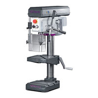
Optimum Opti drill B 28H Operating Manual (176 pages)
Bench drilling machine Upright drilling machine
Brand:
Optimum
| Category:
Drill
| Size: 6.43 MB
Table of Contents
Table of Contents
2
Sicherheit
7
Sicherheitshinweise (Warnhinweise)
7
Gefahren-Klassifizierung
7
Weitere Piktogramme
8
Bestimmungsgemäße Verwendung
9
Vernünftigerweise Vorhersehbare Fehlanwendung
10
Vermeidung von Fehlanwendungen
11
Gefahren, die von der Bohrmaschine Ausgehen
11
Qualifikation des Personals
12
Zielgruppe
12
Autorisierte Personen
13
Bedienerpositionen
14
Sicherheitsmaßnahmen während des Betriebs
14
Sicherheitseinrichtungen
14
Sicherheitsüberprüfung
15
NOT-Halt-Schlagschalter
16
Bohrtisch
16
Trennende Schutzvorrichtungen
16
1.12.1 Schutzabdeckung der Riemenscheiben
16
1.12.2 Bohrfutterschutz
17
Körperschutzmittel
17
Sicherheit während des Betriebs
17
Sicherheit bei der Instandhaltung
18
1.15.1 Abschalten und Sichern der Bohrmaschine
18
Verwenden von Hebezeugen
18
1.16.1 Mechanische Wartungsarbeiten
18
Unfallbericht
19
Elektrik
19
Prüffristen
19
Technische Daten
20
Elektrischer Anschluss
20
Bohrleistung
20
Spindelaufnahme
20
Bohrtisch
20
Platzbedarf
20
Emissionen
21
Drehzahlen Typ H
21
Drehzahlen Typ HV
21
Umgebungsbedingungen
21
Betriebsmittel
21
Abmessungen B24H
23
Abmessungen B24HV
24
Abmessungen B28H
25
Abmessungen B28HV
26
Anlieferung, Innerbetrieblicher Transport und Auspacken
27
Hinweise zu Transport, Aufstellung und Auspacken
27
Allgemeine Gefahren Beim Innerbetrieblichen Transport
27
Lieferumfang
28
Aufstellen und Montieren
28
Anforderungen an den Aufstellort
28
Montieren
28
Montieren von Standfuß und Bohrsäule
29
Montieren des Bohrtisches B24H - B24HV
30
Montieren des Bohrtisches B28H - B28HV
30
Montieren des Bohrkopfes
32
Aufstellen
33
Befestigen
33
Montageskizzen
34
Erste Inbetriebnahme
36
Elektrischer Anschluss
36
Warmlaufen der Maschine
37
Bedienung
38
Sicherheit
38
Bedien- und Anzeigeelemente
38
Bohrmaschine B24H - B24HV
38
Bohrmaschine B28H - B28HV
39
Bedienfeld B24H - B24HV
40
Bedienfeld B28H - B28HV
40
Maschine Einschalten B24H - B28H
42
Maschine Einschalten B24HV - B28HV
42
Maschine Ausschalten B24H - B28H
42
Maschine Ausschalten B24HV - B28HV
42
Drehzahlveränderung
43
Drehzahltabelle B24H
43
Drehzahltabelle B24HV
44
Drehzahltabelle B28H
44
Drehzahltabelle B28HV
45
Bohrtiefenanschlag
45
Ausbau, Einbau von Bohrfuttern und Bohrern
46
Verwenden des Schnellspann-Bohrfutters
46
Ausbau Bohrfutter B24H - B24HV
46
Ausbau mit Integriertem Austreiber an der B28H - B28HV
47
Einbau Bohrfutter B24H - B24HV und B28H - B28HV
48
Kühlung
48
Vor dem Arbeitsgang
49
Während dem Arbeitsgang
49
Ermitteln der Schnittgeschwindigkeit und der Drehzahl
51
Tabelle Schnittgeschwindigkeiten/ Vorschub
51
Drehzahltabelle
51
Beispiel zur Rechnerischen Ermittlung der Erforderlichen Drehzahl an Ihrer Bohrmaschine
53
Instandhaltung
54
Sicherheit
54
Vorbereitung
54
Wiederinbetriebnahme
55
Inspektion und Wartung
55
Instandsetzung
60
Kundendiensttechniker
60
Kühlschmierstoffe und Behälter
61
Prüfplan für Wassergemischte Kühlschmierstoffe
62
Störungen
63
Anhang
65
Urheberrecht
65
Terminologie/Glossar
65
Änderungsinformationen Betriebsanleitung
65
Mangelhaftungsansprüche / Garantie
66
Entsorgungshinweis / Wiederverwertungsmöglichkeiten
66
Außer Betrieb Nehmen
67
Entsorgung der Neugeräte-Verpackung
67
Entsorgung des Altgerätes
67
Entsorgung der Elektrischen und Elektronischen Komponenten
67
Entsorgung der Schmiermittel und Kühlschmierstoffe
68
Entsorgung über Kommunale Sammelstellen
68
Produktbeobachtung
68
Lagerung
69
Safety
75
Safety Instructions (Warning Notes)
75
Classification of Hazards
75
Other Pictograms
76
Intended Use
77
Reasonably Foreseeable Misuse
78
1.3.1 Avoiding Misuse
79
Possible Dangers Caused by the Drilling Machine
79
Qualification of Personnel
80
Target Group
80
Authorized Persons
81
Operator Positions
82
Safety Measures During Operation
82
Safety Devices
82
Safety Check
83
Emergency-Stop Push Button
84
Drilling Table
84
Separating Protective Devices
84
1.12.1 Protective Cover of the V-Belts
84
1.12.2 Drill Chuck Guard
85
Personal Protective Equipment
85
Safety During Operation
85
Safety During Maintenance
86
1.15.1 Disconnecting and Securing the Drilling Machine
86
Using Lifting Equipment
86
1.16.1 Mechanical Maintenance
86
Accident Report
87
Electrical System
87
Inspection Deadlines
87
Technical Specification
88
Electrical Connection
88
Drilling Capacity
88
Spindle Seat
88
Drilling Table
88
Required Space
88
Emissions
89
Speeds Type H
89
Speeds Type HV
89
Environmental Conditions
89
Operating Material
89
Dimensions B24H
91
Dimensions B24HV
92
Dimensions B28H
93
Dimensions B28HV
94
Delivery, Interdepartmental Transport and Unpacking
95
Notes on Transport, Installation and Unpacking
95
General Risks During Internal Transport
95
Scope of Delivery
96
Set-Up and Assembly
96
Requirements Regarding the Installation Site
96
Assembly
96
3.4.1 Mounting of Base and Drill Column
97
Assembly of the Drilling Machine Table B24H - B24HV
98
Assembly of the Drilling Machine Table B28H - B28HV
98
Fitting the Drill Head
100
Installation
101
Fixing
101
Installation Drawings
102
First Commissioning
104
Electrical Connection
104
3.6.2 Warming up the Machine
105
Operation
106
Safety
106
Control and Indicating Elements
106
Drilling Machine B24H - B24HV
106
4.2.2 Drilling Machine B28H - B28HV
107
Control Panel B24H - B24HV
108
Control Panel B28H - B28HV
108
Gb B24H | B24Hv | B28H | B28Hv
109
Switching the Machine B24H - B28H on
110
Switching the Machine B24HV - B28HV on
110
Switching the Machine B24H - B28H off
110
Switching the Machine B24HV - B28HV off
111
Speed Variation
111
Speed Table B24H
112
Speed Table B24HV
112
Speed Table B28H
113
Speed Table B28HV
114
Drill Depth Stop
114
Disassembly, Assembly of Drill Chucks and Drill Bits
115
Use of the Quick-Action Drill Chuck
115
Disassembly of the Drill Chuck B24H - B24HV
115
Disassembly with the Integrated Drill Drift on the B28H - B28HV
116
Mounting the Drill Chuck B24H - B24HV and B28H - B28HV
117
Cooling
117
Before Starting Work
118
During Work
118
Determining the Cutting Speed and the Speed
120
Speed Table
120
Example for Calculating the Required Speed on Your Drilling Machine
122
Maintenance
123
Safety
123
Preparation
123
Restarting
123
Inspection and Maintenance
124
Repair
129
Customer Service Technician
129
Cooling Lubricants and Tanks
130
Inspection Plan for Water-Mixed Cooling Lubricants
131
Malfunctions
132
Appendix 8.1 Copyright
134
Terminology/Glossary
134
Change Information Operating Manual
134
Liability Claims/Warranty
135
Advice for Disposal / Options of Reuse
135
8.5.1 Decommissioning
136
Disposal of New Device Packaging
136
Disposal of the Old Device
136
Disposal of Electrical and Electronic Components
136
8.5.5 Disposal of Lubricants and Coolants
137
Disposal Via Municipal Collection Facilities
137
Product Follow-Up
137
Storage
138
Ersatzteile - Spare Parts
143
Ersatzteilbestellung - Ordering Spare Parts
143
Hotline Ersatzteile - Spare Parts Hotline
143
Service Hotline
143
Ersatzteilzeichnung B24H - Spare Parts Drawing B24H
144
Ersatzteilzeichnung B24HV - Spare Parts Drawing B24HV
149
Schaltplan - Wiring Diagram B24H / B28H - 230 V
156
Schaltplan - Wiring Diagram B24HV
157
Ersatzteilzeichnung B28H - Spare Parts Drawing B28H
158
Ersatzteilzeichnung B28HV - Spare Parts Drawing B28HV
164
Schaltplan - Wiring Diagram - B28H - 400V
172
Schaltplan - Wiring Diagram - B28HV 1-2
173
Schaltplan - Wiring Diagram - B28HV 2-2
174
Advertisement
Optimum Opti drill B 28H Operating Manual (113 pages)
Bench drilling machine
Brand:
Optimum
| Category:
Drill
| Size: 5.15 MB
Table of Contents
Table of Contents
2
1 Safety
6
Safety Instructions (Warning Notes)
6
Classification of Hazards
6
Other Pictograms
7
Intended Use
8
Reasonably Foreseeable Misuse
9
Avoiding Misuse
10
Possible Dangers Caused by the Drilling Machine
10
Qualification of Personnel
11
Target Group
11
Authorized Persons
12
Operator Positions
13
Safety Measures During Operation
13
Safety Devices
13
Safety Check
14
Emergency-Stop Push Button
15
Drilling Table
15
Separating Protective Devices
15
Protective Cover of the V-Belts
15
Drill Chuck Guard
16
Personal Protective Equipment
16
Safety During Operation
16
Safety During Maintenance
17
Disconnecting and Securing the Drilling Machine
17
Using Lifting Equipment
17
Mechanical Maintenance
17
Accident Report
18
Electrical System
18
Inspection Deadlines
18
2 Technical Specification
19
Electrical Connection
19
Drilling Capacity
19
Spindle Seat
19
Drilling Table
19
Required Space
19
Emissions
20
Speeds Type H
20
Speeds Type HV
20
Environmental Conditions
20
Operating Material
20
Dimensions B24H
22
Dimensions B24HV
23
Dimensions B28H
24
Dimensions B28HV
25
3 Delivery, Interdepartmental Transport and Unpacking
26
Notes on Transport, Installation and Unpacking
26
General Risks During Internal Transport
26
Scope of Delivery
27
Set-Up and Assembly
27
Requirements Regarding the Installation Site
27
Assembly
27
Mounting of Base and Drill Column
28
Assembly of the Drilling Machine Table B24H - B24HV
29
Assembly of the Drilling Machine Table B28H - B28HV
29
Fitting the Drill Head
31
Installation
32
Fixing
32
Installation Drawings
33
First Commissioning
35
Electrical Connection
35
Warming up the Machine
36
4 Operation
37
Safety
37
Control and Indicating Elements
37
Drilling Machine B24H - B24HV
37
Drilling Machine B28H - B28HV
38
Control Panel B24H - B24HV
39
Control Panel B28H - B28HV
39
Switching the Machine B24H - B28H on
41
Switching the Machine B24HV - B28HV on
41
Switching the Machine B24H - B28H off
41
Switching the Machine B24HV - B28HV off
42
Speed Variation
42
Speed Table B24H
43
Speed Table B24HV
43
Speed Table B28H
44
Speed Table B28HV
45
Drill Depth Stop
45
Disassembly, Assembly of Drill Chucks and Drill Bits
46
Use of the Quick-Action Drill Chuck
46
Disassembly of the Drill Chuck B24H - B24HV
46
Disassembly with the Integrated Drill Drift on the B28H - B28HV
47
Mounting the Drill Chuck B24H - B24HV and B28H - B28HV
48
Cooling
48
Before Starting Work
49
During Work
49
5 Determining the Cutting Speed and the Speed
51
Speed Table
51
Examples to Calculatory Determine the Required Speed for Your Drilling Machine
53
6 Maintenance
54
Safety
54
Preparation
54
Restarting
54
Inspection and Maintenance
55
Repair
60
Customer Service Technician
60
Cooling Lubricants and Tanks
61
Inspection Plan for Water-Mixed Cooling Lubricants
62
7 Ersatzteile - Spare Parts
63
Ersatzteilbestellung - Ordering Spare Parts
63
Hotline Ersatzteile - Spare Parts Hotline
63
Service Hotline
63
Ersatzteilzeichnung B24H - Spare Parts Drawing B24H
64
Bohrkopf B24H - Drilling Head B24H
64
Säule und Bohrtisch B24H - Column and Drilling Table B24H
65
Keilriemenscheiben B24H - Pulleys B24H
66
Ersatzteilzeichnung B24HV - Spare Parts Drawing B24HV
70
Bohrkopf B24HV - Drilling Head B24HV
70
Säule und Bohrtisch B24HV - Column and Drilling Table B24HV
71
Keilriemenscheiben B24HV - Pulleys B24HV
72
Ersatzteilliste B24HV - Parts List B24HV
72
Maschinenschilder - Machine Labels B24H
76
Maschinenschilder - Machine Labels B24HV
77
Schaltplan - Wiring Diagram B24H / B28H - 230 V
79
Schaltplan - Wiring Diagram B24HV
80
Ersatzteilzeichnung B28H - Spare Parts Drawing B28H
81
Bohrkopf B28H - Drilling Head B28H
81
Säule und Bohrtisch B28H - Column and Drilling Table B28H
82
Keilriemenscheiben B28H - Pulleys B28H
83
Ersatzteilliste B28H - Parts List B28H
84
Ersatzteilzeichnung B28HV - Spare Parts Drawing B28HV
88
Bohrkopf B28HV - Drilling Head B28HV
88
Säule und Bohrtisch B28HV - Column and Drilling Table B28HV
89
Keilriemenscheiben B28HV - Pulleys B28HV
90
Ersatzteilliste B28HV - Parts List B28HV
90
Maschinenschilder - Machine Labels B28H
95
Maschinenschilder - Machine Labels - B28HV
97
Schaltplan - Wiring Diagram - B28H - 400V
98
Schaltplan - Wiring Diagram - B28HV 1-2
99
Schaltplan - Wiring Diagram - B28HV 2-2
100
8 Malfunctions
101
9 Appendix
103
Copyright
103
Terminology/Glossary
103
Change Information Operating Manual
103
Liability Claims/Warranty
104
Advice for Disposal / Options of Reuse
104
Decommissioning
105
Disposal of New Device Packaging
105
Disposal of the Old Device
105
Disposal of Electrical and Electronic Components
105
Disposal of Lubricants and Coolants
106
Disposal Via Municipal Collection Facilities
106
Rohs, 2011/65/EU
106
Product Follow-Up
106
Storage
107
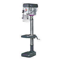
Optimum Opti drill B 28H Operating Manual (100 pages)
Bench drilling machine, Upright drilling machine
Brand:
Optimum
| Category:
Drill
| Size: 5.42 MB
Table of Contents
Table of Contents
2
1 Safety
6
Safety Instructions (Warning Notes)
6
Classification of Hazards
6
Other Pictograms
7
Intended Use
8
Reasonably Foreseeable Misuses
9
Avoiding Misuses
9
Possible Dangers Caused by the Drilling Machine
9
Qualification of Personnel
10
Target Group
10
Authorized Persons
11
Operator Positions
12
Safety Measures During Operation
12
Safety Devices
12
Safety Check
13
EMERGENCY-STOP Push Button
14
Drilling Table
14
Separating Protective Devices
14
Protective Cover of the V-Belts
14
Drill Chuck Protection
15
Individual Protection Gear
15
Safety During Operation
16
Safety During Maintenance
16
Disconnecting and Securing the Drillnig Machine
16
Using Lifting Equipment
16
Mechanical Maintenance Work
17
Accident Report
17
Electrical System
17
2 Technical Data
18
Electrical Connection
18
Drilling Capacity
18
Spindle Seat
18
Drilling Table
18
Required Space
18
Speeds Type H
18
Emissions
19
Speeds Type HV
19
Environmental Conditions
19
Operating Material
19
Dimensions B24H
20
Dimensions B24HV
21
Dimensions B24H
22
Dimensions B24HV
23
3 Assembly 3.1 Scope of Delivery
24
Transport
24
Storage
25
Installation and Assembly
26
Requirements to the Installation Site
26
Assembly
27
Mounting of Base and Drill Column
27
Assembly of the Drilling Machine Table B24H - B24HV
28
Fitting the Drill Head
30
Installation
31
Fixing
31
Installation Drawings
32
First Commissioning
34
Warming up the Machine
34
Electrical Connection
35
4 Operation
36
Safety
36
Control and Indicating Elements
36
Drilling Machine B24H - B24HV
36
Drilling Machine B28H - B28HV
37
Drilling Machine B24H - B24HV
38
Control Panel B28H - B28H (Vario)
38
Turn the Machine on B24H / B28H
40
Turn the Machine on B24HV / B28HV
40
Turn the Machine off B24H / B28H
40
Speed Variation
41
Speed Table B24H
41
Speed Table B24HV
42
Speed Table B28H
42
Speed Table B28HV
43
Drill Depth Stop
43
Disassembly, Assembly of Drill Chucks and Drill Bits
44
Use of Quick Action Drill Chuck
44
Disassembly of the Drill Chuck B24H - B24HV
44
Disassembly with the Integrated Drill Drift on the B28H- B28HV
45
Mounting the Drill Chuck B24H - B24HV und B28H - B28HV
46
Cooling
46
Before Starting Work
47
During Work
47
5 Determining the Cutting Speed and the Speed
49
Speed Table
49
Examples to Calculatory Determine the Required Speed for Your Drilling Machine
51
6 Maintenance
52
Safety
53
Preparation
53
Restarting
53
Inspection and Maintenance
53
Repair
57
7 Ersatzteile - Spare Parts
58
Ersatzteilzeichnung B24H - Spare Parts Drawing B24H
58
Bohrkopf B24H - Drilling Head B24H
58
Säule und Bohrtisch B24H - Column and Drilling Table B24H
59
Keilriemenscheiben B24H - Pulleys B24H
60
Ersatzteilliste B24H - Parts List B24H
60
B24Hv
63
Bohrkopf B24HV - Drilling Head B24HV
63
Säule und Bohrtisch B24HV - Column and Drilling Table B24HV
64
Keilriemenscheiben B24HV - Pulleys B24HV
65
Ersatzteilliste B24HV - Parts List B24HV
65
Maschinenschilder - Machine Labels B24H
68
Maschinenschilder - Machine Labels B24H Vario
69
Schaltplan - Wiring Diagram B24H - 230 V
70
Schaltplan - Wiring Diagram B24H - 400V
71
Schaltplan - Wiring Diagram B24HV
72
Ersatzteilzeichnung B28H - Spare Parts Drawing B28H
73
Bohrkopf B28H - Drilling Head B28H
73
Säule und Bohrtisch B28H - Column and Drilling Table B28H
74
Keilriemenscheiben B28H - Pulleys B28H
75
Ersatzteilliste B28H - Parts List B28H
75
Ersatzteilzeichnung B28HV - Explosion Drawing B28HV
78
Bohrkopf B28HV - Drilling Head B28HV
78
Säule und Bohrtisch B28HV - Column and Drilling Table B28HV
79
Keilriemenscheiben B28HV - Pulleys B28HV
80
Ersatzteilliste B28HV - Parts List B28HV
80
Maschinenschilder - Machine Labels B28H
84
Maschinenschilder - Machine Labels - B28HV
85
Schaltplan - Wiring Diagram - B28H - 400V
86
Schaltplan - Wiring Diagram - B28HV 1-2
87
Schaltplan - Wiring Diagram - B28HV 2-2
88
8 Malfunctions
89
9 Appendix
91
Copyright
91
Terminology/Glossary
91
Change Information Operating Manual
91
Liability Claims for Defects / Warranty
92
Note Regarding Disposal / Options to Reuse
92
Decommissioning
93
Disposal of the Packaging of New Devices
93
Disposing of the Old Device
93
Disposal of Electrical and Electronic Components
93
Disposal of Lubricants and Coolants
94
Disposal Via Municipal Collection
94
Rohs , 2002/95/CE
94
Product Follow-Up
94
Advertisement
Advertisement
Related Products
Optimum OPTIdrill B 16H
Optimum OPTIdrill B20
Optimum Optidrill B 24HV
Optimum Optidrill B 28HV
Optimum Optidrill B 34H
Optimum OPTI drill D 17Pro
Optimum OPTI drill D 23Pro
Optimum OPTI drill D 26Pro
Optimum OPTI drill D 33Pro
Optimum OPTI SD 500AV
Optimum Categories
Kettle
Drill
Kitchen Appliances
Blender
Juicer
More Optimum Manuals
Login
Sign In
OR
Sign in with Facebook
Sign in with Google
Upload manual
Upload from disk
Upload from URL