
Subscribe to Our Youtube Channel
Related Manuals for Viavi SmartClass OLP-87


Summary of Contents for Viavi SmartClass OLP-87
- Page 1 OLP-87/OLP-87P SmartClass™ Fiber PON Power Meter Operating manual BN 2305/98.21 2019.06 English...
- Page 2 430 N. McCarthy Blvd. • Milpitas, CA 95035 USA Copyright © Copyright 2019 Viavi Solutions Inc. All rights reserved. Viavi and the Viavi logo are trademarks of Viavi Solutions Inc. All other trademarks and registered trademarks are the properties of their respective owners.
-
Page 3: Table Of Contents
ONTENTS ONTENTS ....... . 6 NTRODUCTION OLP-87/OLP-87P power meters ..... . . 6 Operating manual update. - Page 4 ONTENTS XGPON O ......50 PERATION General information....... . 50 Select a predefined XGPON view .
- Page 5 ONTENTS ..... . . 87 RDERING NFORMATION OLP-87/OLP-87P stand alone units ....87 Included items.
-
Page 6: Introduction
NTRODUCTION OLP-87/OLP-87P POWER METERS NTRODUCTION OLP-87/OLP-87P power meters This manual applies to the following models: • BN 2305/01 • BN 2305/36 • BN 2305/21 • BN 2305/66 • BN 2305/26 • BN 2306/36 • BN 2305/11 • BN 2306/66 • BN 2305/31 The SmartClass™... - Page 7 NTRODUCTION OLP-87/OLP-87P POWER METERS An integrated pass/fail analysis feature simplifies standard conformity testing and provides unambiguous measurement result presentation. With integrated report generation, all measurement data can be summarized within a professional, industry standard test report. Battery operation from AA dry cells or from a rechargeable Li-Ion Battery Pack ensure long operating time in the field and a robust, shock-proof design makes the SmartClass™...
- Page 8 NTRODUCTION OLP-87/OLP-87P POWER METERS BN 2305/xy (partially BN 2306/xy) 01, 21, 26 11, 31, 36 1550 nm – 1270 nm – – 1578 nm – – Broadband Power Meter 1) Software option Please note that the descriptions which follow apply to OLP-87/ OLP-87P/xy as indicated in the table above.
- Page 9 NTRODUCTION OLP-87/OLP-87P POWER METERS Broadband mode The 1310/1490 nm instruments feature non-selective power measurements via the OLT port. In this mode, the OLP-87/OLP- 87P FTTx tester behaves like a standard broadband power meter, e.g. attenuation measurements can be made in the usual way using a suitable optical source.
-
Page 10: Operating Manual Update
If the operating instructions about features provided by your instrument are missing, please visit the Viavi web site to check if additional information is available. To download the latest user manual: Visit the Viavi web site at http://updatemyunit.net. -
Page 11: Symbols Used In This Operating Manual
NTRODUCTION YMBOLS USED IN THIS OPERATING MANUAL Symbols used in this operating manual Various elements are used in this operating manual to draw attention to special meanings or important points in the text. Symbols and terms used in warnings The following warnings, symbols and terms are used in this document in compliance with the American National Standard ANSI Z535.6-2011: NOTICE... - Page 12 NTRODUCTION YMBOLS USED IN THIS OPERATING MANUAL The following elements are used in this operating manual: Requirement This requirement must be met first; e.g. The system is switched on. Instruction Follow the instructions given (the numbers indicate the order in which the instructions should be followed); e.g. Select mode.
-
Page 13: Safety Information
AFETY NFORMATION ARNING SYMBOLS ON THE UNIT AFETY NFORMATION Warning symbols on the unit Warning symbols indicating a potential hazard In all cases where the unit is labeled with a warning symbol, the operating manual must be consulted to learn more about the nature of the potential hazard and any action that must be taken. -
Page 14: Laser Safety
AFETY NFORMATION ASER SAFETY Laser safety WARNING Dangerous laser radiation Laser radiation can cause irreparable damage to eyes and skin. The maximum permitted power for the OLP-87 means that the optical input signals can reach hazard level. Bear this in mind when using the OLP-87. In particular, the instrument is equipped with a through channel that transmits all the optical radiation from the input to the output without attenuation, even when the OLP-87 is switched off. -
Page 15: Battery Operation
AFETY NFORMATION ATTERY OPERATION Battery operation WARNING Explosion danger Short-circuiting the batteries can result in overheating, explosion, or ignition of the batteries and their surround- ings. Never short-circuit the battery contacts by touching both contacts simultaneously with an electrical conducting object. Only use AA size dry batteries or rechargeable batteries. - Page 16 AFETY NFORMATION PS4 U AC/DC P NIVERSAL OWER UPPLY Environmental conditions NOTICE Ambient temperature too high/low Temperatures outside the operating range of 0 to +40 °C can damage the PS4 Universal AC/DC Power Supply or adversely affect its function and safety. Only operate the PS4 Universal AC/DC Power Supply indoors.
-
Page 17: Getting Started
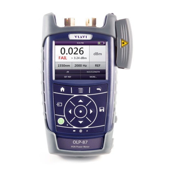
This is particularly likely if the packaging is visibly damaged. If there is damage, do not attempt to operate the instrument. Doing so can cause further damage. In case of damage, please contact your local Viavi sales company. Addresses can be found at www.viavisolutions.com. Recovery following storage/shipping Condensation can occur if a instrument that is stored or shipped at a low temperature is brought into a warm room. - Page 18 ETTING TARTED NPACKING THE INSTRUMENT Instrument overview Fig. 2 Front view OLP-87/OLP-87P and OLP-87P Patch cord microscope (PCM) with FMAE adapter PCM controls: focus control, automated Pass/Fail analysis, magnification control Connector interface Test head cover (green for APC- and gray for PC connectors) 3.5 inch touchscreen Key pad (operator control panel) Battery compartment and stand (on rear of instrument)
- Page 19 ETTING TARTED NPACKING THE INSTRUMENT Connector panel Fig. 3 Connector panel of a 2 wavelength instrument Optical connector 1 Downstream at PON measurement Optical connector 2 Upstream at PON measurement Fig. 4 Connector panel of a 3 wavelength instrument Optical connector 1 Downstream at PON measurement Input port for broadband measurement (optional) Optical connector 2...
- Page 20 ETTING TARTED NPACKING THE INSTRUMENT Fig. 5 External power supply connector and communication inter- faces Ethernet port (RJ-45) External power supply connector USB 2.0 host port (Type A) USB 2.0 device port (Type Micro-B) Power supply The following power sources can be used to operate the OLP-87: •...
- Page 21 ETTING TARTED NPACKING THE INSTRUMENT Battery operation WARNING Dangers when handling batteries Handling batteries may be dangerous. Please note the fol- lowing safety instructions. Please note the battery operation safety information in the chapter “Battery operation” on page Replacing batteries Do not replace individual batteries.
- Page 22 ETTING TARTED NPACKING THE INSTRUMENT Insert new or replace the RBP2 LiIon Battery Pack. – or – Switch from non-rechargeable batteries to rechargeable ones by replacing the battery tray with a new battery pack (or vice versa). Close the battery compartment. Press the key to switch on.
- Page 23 You will often be able to return used batteries to the place where you purchase new ones. Any dry or rechargeable batteries that you purchased from Viavi can be returned to one of our Service Centers for disposal. Operation from AC power...
- Page 24 ETTING TARTED NPACKING THE INSTRUMENT Slide the AC line plug adapter into the slot. The PS4 Universal AC/DC Power Supply is ready for use. Fig. 7 PS4 Universal AC/DC Power Supply To change the AC line plug adapter: Squeeze both sides of the PS4 latch lock (see Fig.
-
Page 25: Connecting Optical Cables
The OLP-87 cannot be powered via the USB interface. Connecting optical cables Mounting test adapters Viavi provides a number of test adapters for connecting the OLP-87 to the interface to be tested. You can connect all standard optical connector types to the instrument using these adapters. - Page 26 ETTING TARTED ONNECTING OPTICAL CABLES Fig. 9 Mounting the JAE test adapter To mount the SENKO test adapter: Open the head cover and remove the protective cap (if still mounted). Unscrew the SENKO test adapter and pull it off vertically. Place the SENKO test adapter vertically on the optical connector.
-
Page 27: Basic Operation
ASIC PERATION WITCHING THE INSTRUMENT ON ASIC PERATION Switching the instrument on/off To switch the instrument on: Press the key to switch on the instrument. To switch the instrument off: Press the key to shift the instrument into hibernate mode. –... -
Page 28: Menus And Display Elements
ASIC PERATION ENUS AND DISPLAY ELEMENTS Menus and display elements Home screen Fig. 11 Home screens: Test applications (screen shows PCM version) (1), Management (2), Settings (3) Menu See page Test applications In this menu you can open test applications. Management In this menu you can: •... - Page 29 ASIC PERATION ENUS AND DISPLAY ELEMENTS Test applications Fig. 12 Test applications (screen shows PCM version) Application See page PONmeter/XGPON (optional) To enable simultaneous power measurement of all upstream & downstream wavelengths on live B/E/G-PON networks. Powermeter/Broadband (optional) To install and maintain cables and networks with the broadband power meter.
- Page 30 ASIC PERATION ENUS AND DISPLAY ELEMENTS Elements in the top bar Project title Indicates the title of the active project WIFI Indicates that Wifi is installed. It does not indicate an active Wifi connection. Bluetooth Indicates that Bluetooth is installed. It does not indicate an active bluetooth connection.
-
Page 31: Navigating In The Menus
ASIC PERATION AVIGATING IN THE MENUS Navigating in the menus Press the key to open the home screen. Depending on the active project type the Projects tab shows the available test applications or the active Workflow project. Press the key to open the context-sensitive menu. Depending on which application is selected, a different menu opens. -
Page 32: Changing System Settings
ASIC PERATION HANGING YSTEM ETTINGS Changing System Settings In the Settings menu you can change instrument settings, get information and help about the instrument, or update the firmware. To open the Settings menu: The home screen is displayed. Select the tab. - Page 33 ASIC PERATION HANGING YSTEM ETTINGS Icon Function See page WiFi To configure the wireless local area network. The last selected item is displayed in magenta. Bluetooth To configure the Bluetooth interface. Brightness To adjust the display brightness. Help To show device information SW Options Not yet available,...
- Page 34 ASIC PERATION HANGING YSTEM ETTINGS Setting the [Screen-Off] interval When [Screen-Off] is set, the display will switch off after the selected interval without any user action. NOTE: [Screen-Off] is only active when no external power supply is connected. In the menu tap the [More] button,...
- Page 35 ASIC PERATION HANGING YSTEM ETTINGS To set 24-hour or 12-hour time: Tap [Time Format]. Select the desired time format. Setting the Ethernet protocol In the menu tap the [More] button, then tap [Ethernet]. To select the IP mode: Tap the [IP Mode] button.
-
Page 36: Wifi Menu (Optional)
ASIC PERATION I MENU OPTIONAL In the menu tap the [More] button, then tap [Factory Reset]. [Yes] to proceed. – or – [No] to cancel. WiFi menu (optional) In the menu tap the [WiFi] button. Editable settings are displayed – Enabled: switch WiFi on/off –... -
Page 37: Updating The Firmware
The latest version of the firmware can be downloaded from the Internet. To find the latest firmware version: Visit the Viavi web site at http://updatemyunit.net. Select your model from the product line. Open the download area and download the latest firmware. - Page 38 ASIC PERATION REATING SCREENSHOTS Set the Add Auto-Increment Number function ON or OFF. If the setting is ON, a number is added to the proposed name, ascending each time that a new screenshot is taken. Edit the Auto-Increment Number field by tapping the pencil button if you want to change the current number.
-
Page 39: Managing Projects
ANAGING PROJECTS REATING A NEW PROJECT ANAGING PROJECTS Stored Measurements are assigned to a project. Therefore a project first has to be created and set to active. As factory setting one Test-Tool project named default is available, which can be edited but not deleted. -
Page 40: Editing A Project
ANAGING PROJECTS DITING A PROJECT Adding a new project: Press the key. The edit menu opens. Tap [Add]. The title edit menu opens. Type in the project title and tap The project is created and displayed in the list. Copying an existing project: Select the project you wish to copy. -
Page 41: Deleting A Project
ANAGING PROJECTS ELETING A PROJECT The changes are immediately effective. Press the button to close the edit menu. Deleting a project Select the project you wish to delete. Press the key and tap [Remove]. [Yes] to permanently delete the project. The project is deleted and removed from the list. -
Page 42: Pon Meter Operation
6 PON METER PERATION ISPLAYING THE FUNCTIONAL OVERVIEW METER PERATION Displaying the functional overview The homescreen is displayed. Tap the [PONmeter] button. Press the key. The menu opens: Fig. 15 PONmeter menu Tap the [More] button. Tap the [Info] button. The functional overview is displayed: Fig. -
Page 43: Displaying Absolute Power Level
6 PON METER PERATION ISPLAYING ABSOLUTE POWER LEVEL Displaying absolute power level The power level is displayed in dBm or Watts (nW, μW, mW) in absolute power level mode. Fig. 17 dBm view in absolute power level The PONmeter screen is displayed. Press the key. - Page 44 6 PON METER PERATION AIL MEASUREMENT Results Thresholds High OVER Over PASS Pass WARN Warn FAIL Fig. 18 Thresholds and result areas These thresholds can be defined separately for each wavelength (1310, 1490 and 1550 nm) and stored together as a threshold set.
- Page 45 6 PON METER PERATION AIL MEASUREMENT The following menu is displayed: To select a saved threshold, press the key and tap the [Select Set] button. Select the desired threshold set. The selected set is displayed. Editing threshold levels The Edit Threshold Sets menu is displayed: To change the threshold, tap on the desired value.
- Page 46 6 PON METER PERATION AIL MEASUREMENT The THRESHOLD SET NAME menu is displayed: Type in the threshold set name. To save the threshold set, tap the [OK] button. – or – To exit from the menu without making any changes press the key.
-
Page 47: Displaying Relative Power Level
6 PON METER PERATION ISPLAYING RELATIVE POWER LEVEL The selected set is displayed. Measuring in Pass/Fail mode NOTE: You must set the threshold levels before you can make measurements in Pass/Fail mode. Select a threshold set. Press the key. Tap the [Pass/Fail] button. -
Page 48: Saving Ponmeter Test Results
6 PON METER PERATION AVING METER TEST RESULTS Setting the reference level The PONmeter screen is displayed. Press the key. Tap the [Store ABS->REF] button to store the reference level. The actual power level is set as the new reference level. The reference level is displayed underneath the wavelength. - Page 49 6 PON METER PERATION AVING METER TEST RESULTS To save current results: The instrument is in application mode and displays the test results (overview or details) to be stored. Press the key. The Save dialog is displayed. As file name the label prefix defined in the project settings is showed on top of the display.
-
Page 50: Xgpon Operation
7 XGPON O PERATION ENERAL INFORMATION XGPON O PERATION General information The operation of the XGPON application is almost the same as the description of the PONmeter application (see “PONmeter Operation” on page 42). The XGPON application differs by additional wavelength options for references and threshold sets. Therefore, only the additional menus of the XGPON application are described in detail in the following. -
Page 51: Delete A Self-Defined View
7 XGPON O PERATION ELETE A SELF DEFINED VIEW The new self defined view is displayed. Delete a self-defined view The XGPON screen is displayed. Press the key. Tap the [More] button. Tap the [Edit Views] button. view table is displayed. ... - Page 52 7 XGPON O PERATION XGPON AVING TEST RESULTS To save current results: The instrument is in application mode and displays the test results (overview or details) to be stored. Press the key. The Save dialog is displayed. As file name the label prefix defined in the project settings is showed on top of the display.
-
Page 53: Probe /Pcm Operation
/PCM O ROBE PERATION ENERAL INFORMATION /PCM O ROBE PERATION General information Dirty and/or damaged connectors are often the root cause of optical network problems. The Probe and PCM applications enable industry standard inspection and automated Pass/Fail testing with report generation of optical connectors/adapters in order to ensure industry standard fiber endface quality and cleanliness. -
Page 54: Fmae Series Adapters For The Pcm
/PCM O ROBE PERATION FMAE SERIES ADAPTERS FOR THE Fig. 20 Patch cord microscope components FMAE adapter QuickCapture™ key Focus Control Magnification Control key FMAE series adapters for the PCM SmartClass™ Fiber devices with the PCM use FMAE series adapters to ensure consistent and accurate inspection for a wide variety connectors and applications. - Page 55 /PCM O ROBE PERATION P5000 EATURES AVAILABLE WITH THE IGITAL ROBE provides fast toggling between two microscope magnification levels - low magnification for high level inspection of the fiber endface and high magnification for detailed inspection of the fiber endface. The P5000i Digital Probe kit sold with the OLP-87 contains the standard barrel assembly (FBPP-BAP1), standard patch cord tips, and standard bulkhead tips.
-
Page 56: Quickcapture™ Key
/PCM O ROBE PERATION ™ UICK APTURE Fig. 22 FBPT series tips for the P5000i Inspection tip Barrel assembly P5000i connection The Probe application requires a P5000i Digital Probe in order to be fully functional (see the list of all accessories in “Digital Probe Microscope”... -
Page 57: File Toolbar
/PCM O ROBE PERATION ILE TOOLBAR To display the live view, tap the [Probe] button. File toolbar Saving a picture It is possible to save the frozen picture from the Digital Probe. Press the key. Edit the file name. Tap the [OK] button. - Page 58 /PCM O ROBE PERATION ONFIGURING THE IGITAL ROBE Press the key and tap the [Test] button. – or – Press the QuickCapture™ key on the Digital Probe if the button action is set to Test. When the test procedure terminates, the information shown on the display depends on the current overlay setting: Press the key, and then the...
- Page 59 /PCM O ROBE PERATION ONFIGURING THE IGITAL ROBE Fig. 23 Pass/Fail analysis – overlay view Magnification Control The Magnification Control allows you to modify the live display from high to low magnification and vice-versa. In the high magnification mode an automatic centering is available. Picture selected: Live Test Allows you to launch a (new) test of the connector...
- Page 60 /PCM O ROBE PERATION ONFIGURING THE IGITAL ROBE The file is saved in the current active group directory on the OLP-87. Freeze mode Once the image is acceptable (sharpness, luminosity are tuned correctly), you may freeze the picture. This feature allows you to store the resulting picture in order to compare it later to others or save it in a file.
-
Page 61: Saving Probe/Pcm Results
/PCM O ROBE PERATION /PCM AVING ROBE RESULTS More Press the key. Tap the [More] button to view or change the storage location, settings and information of the Digital Probe. Saving Probe/PCM results Images can easily be saved by pressing the key. - Page 62 /PCM O ROBE PERATION /PCM AVING ROBE RESULTS As file name the label prefix defined in the project settings is showed on top of the display. To edit the file name, tap the name, edit it and tap [OK]. To change the ID, tap [Decrement or [Increment ID].
-
Page 63: Broadband Operation
ROADBAND PERATION ENERAL INFORMATION ROADBAND PERATION General information Broadband measurement is available by enabling the software option for 1310/1490/1550nm and 1270/1310/1490/1550/ 1578nm instruments. Fig. 24 Input port for broadband measurement BB-OPM Setting and selecting wavelengths The OLP-87/OLP-87P provides several ways to select a wavelength: •... - Page 64 ROADBAND PERATION ETTING AND SELECTING WAVELENGTHS Grafik korrekt für Broadband Operation? Fig. 25 Measurement display (screen shows actual power level (upper), selected wavelength (lower left) and modulation frequency (lower right) Grafik korrekt für Broadband Operation? Fig. 26 Measurement display (screen shows the settings menu) Creating and editing wavelengths in the ...
- Page 65 ROADBAND PERATION ETTING AND SELECTING WAVELENGTHS table is displayed: To add a wavelength: The Edit Table menu in Powermeter mode is displayed. Press the key and tap the [Add button. Type in the desired value. Tap the [OK] button.
-
Page 66: Enabling Auto-L Mode
Enabling Auto- mode Auto is a special feature developed by Viavi that allows you to identify wavelengths automatically. To do this, the signal is modulated at a certain frequency (by a light source equipped with Auto ), which can be detected by a Viavi OLP-87/OLP-87P. -
Page 67: Selecting And Changing The Power Display Mode
ROADBAND PERATION ELECTING AND CHANGING THE POWER DISPLAY MODE The menu opens: Tap the [Auto button to switch Auto mode on/off. The checkmark is set or removed. Displaying modulated signals The OLP-87/OLP-87P automatically detects the modulation frequency of light signals modulated at the fixed frequencies of 270 Hz, 1 kHz, and 2 kHz. -
Page 68: Displaying Relative Power Level
ROADBAND PERATION ISPLAYING RELATIVE POWER LEVEL To toggle between the display modes, tap the power level in the measurement display. – or – Press the key and tap the [dBm/Watt] button to toggle between both options. – or – Tap the [dB] button. -
Page 69: Saving Broadband Test Results
ROADBAND PERATION AVING ROADBAND TEST RESULTS Tap on the left side of the touchscreen. The Reference edit mode is displayed. Type in the desired value. Tap the [OK] button. For other wavelengths, repeat steps 1 through 3 as required. To edit the reference level in the More menu: The Powermeter screen is displayed. - Page 70 ROADBAND PERATION AVING ROADBAND TEST RESULTS As file name the label prefix defined in the project settings is showed on top of the display. Defined label name. Tap field to edit label name. • PONmeter: Number of already saved PONmeter results. •...
-
Page 71: Data Management
10 D ANAGEMENT AVING RESULTS ANAGEMENT NOTE: Results are always stored under the currently selected (active) project. Thus, to display stored results the desired project must be set to active first (see“Managing projects” on page 39). Saving results Saving results is explained in the descriptions of each application. - Page 72 10 D ANAGEMENT , XGPON ATA MANAGEMENT OF METER ROADBAND TESTS To show all columns of the overview: Press the right/left arrow keys to show additional information. The displayed information depends on the selected application. Measurement Data of ... Test ggf.
- Page 73 10 D ANAGEMENT , XGPON ATA MANAGEMENT OF METER ROADBAND TESTS The first selected result will be displayed. Grafik korrekt für PON- meter, XGPON Broadband Operation? Fig. 28 Test results Press the key and tap the [Next] [Previous] button to display other results.
-
Page 74: Data Management Of Probe And Pcm Tests
10 D ANAGEMENT ATA MANAGEMENT OF ROBE AND TESTS Data management of Probe and PCM tests Recalling stored test results Stored test results are displayed directly from the menu in the Probe/PCM application. The Probe or PCM application is selected. Press the key. - Page 75 10 D ANAGEMENT ATA MANAGEMENT OF ROBE AND TESTS The check mark shows the selected test. To select multiple tests: Repeat step 1 to select multiple entries. To select all tests: Press the key and tap [Select All]. To deselect all tests: Press the key and tap [Deselect All].
- Page 76 10 D ANAGEMENT ATA MANAGEMENT OF ROBE AND TESTS Sorting test results The measurement data overview is displayed. Press the key. Tap the [More] button, then tap the [Sort Order] button. Select the desired sorting order. Show/hiding the overview columns The measurement data overview is displayed.
-
Page 77: Exporting Results To Usb
Smart Reporter. Making a report In order to make a report, please download the FiberChekPRO™ or SmartReporter software from the Viavi web site http://updatemyunit.net. Connect your instrument to your PC via the USB port and follow the instructions on the screen. -
Page 78: Maintenance
11 M AINTENANCE LEANING THE TEST PORT AINTENANCE WARNING Dangerous voltage and invisible laser radiation Maintenance or cleaning of the instrument while it is con- nected or operating may damage the instrument or injure you. Make sure that the instrument is switched off and disconnected from all power sources and optical radiation sources before maintenance or cleaning. -
Page 79: Remote Control
12 R EMOTE ONTROL LEANING THE INSTRUMENT EMOTE ONTROL Remote Command Documentation Please visit the Viavi web site at http://updatemyunit.net the latest Remote Command Documentation “SCF RC Docs.exe“ (self extracting zip-file). OLP-87/OLP-87P... -
Page 80: Environmental Compliance
The authority to operate this equipment is conditioned by the requirements that no modifications be made to the equipment unless the changes or modifications are expressly approved by Viavi. NOTE: To comply with FCC RF exposure compliance requirements, a separation distance of at least 20 cm must be maintained between the antenna of this device and all persons. - Page 81 13 E NVIRONMENTAL COMPLIANCE LEANING THE INSTRUMENT EU Radio Equipment Directive In accordance with Article 10.8 of the EU Radio Equipment Directive 2014/53/EU, the following table provides information on the frequency bands and the maximum RF transmit power of this product for sale in the EU: Frequency range Channels used Max.
-
Page 82: Specifications
14 S PECIFICATIONS X SPECIFICATIONS PECIFICATIONS FTTx specifications General 1310/1490/ 1310/ 1270/1310/ 1550 nm 1490 nm 1490/1550/ 1578 nm Downstream 1490/ 1490 nm 1578/ measurement 1550 nm 1550 nm Upstream 1310 nm, burst mode 1270 nm, measurement burst mode Supported net- G-PON, B-PON, E-PON G-PON, works... - Page 83 14 S PECIFICATIONS X SPECIFICATIONS Upstream measurements ONT to OLT Data signals at 1310 nm 1310/1490/ 1310/ 1270/1310/ 1550 nm 1490 nm 1490/1550/ 1578 nm Power measure- Burst: -35 to +13 dBm ment range CW: -40 to +13 dBm Measurement Burst mode measurement mode Max.
- Page 84 14 S PECIFICATIONS X SPECIFICATIONS Downstream measurements OLT to ONT Data signals at 1490 nm 1310/1490/ 1310/ 1270/1310/ 1550 nm 1490 nm 1490/1550/ 1578 nm Power measure- -50 to +13 dBm ment range Max. permitted +15 dBm input level 1) 2) Power uncertainty ±...
-
Page 85: General Specifications
14 S PECIFICATIONS ENERAL SPECIFICATIONS Video signals at 1550 nm 1310/1490/ 1270/1310/1490/ 1550 nm 1550/1578 nm Power measurement range -50 to +26 dBm Max. permitted input level +27 dBm 1) 2) Power uncertainty ± 0.5 dB Spectral pass band 1535 to 1565 nm Isolation 1310 nm >... - Page 86 14 S PECIFICATIONS ENERAL SPECIFICATIONS Weight 750 g Operating temperature range -5 °C to +45 °C Storage temperature range -25 °C to +55 °C Broadband power meter mode 1310/1490 nm version only Power measurement range -50 to +13 dBm Max. permitted input level +15 dBm 1) 2) Power uncertainty (2 )
-
Page 87: Ordering Information
15 O RDERING NFORMATION OLP-87/OLP-87P STAND ALONE UNITS RDERING NFORMATION OLP-87/OLP-87P stand alone units OLP-87 1310/1490 nm, PC universal adapter BN 2305/01 1310/1490 nm, SC-PC fixed adapter BN 2305/06 1310/1490 nm, APC universal adapter BN 2305/21 1310/1490 nm, SC-APC fixed adapter BN 2305/26 1310/1490/1550 nm, PC universal adapter BN 2305/11... -
Page 88: Included Items
15 O RDERING NFORMATION NCLUDED ITEMS Included items Stand alone units • SmartClass™ Fiber instrument • Soft shoulder case for SmartClass™ Fiber + accessories • Electronic tool kit with Operating Manual, datasheet and Smart-Reporter SW on USB flash drive • Two optical adapters: SC type or selectable SC, FC, DIN, ST, LC in universal version •... -
Page 89: Kits
15 O RDERING NFORMATION Kits OLP-87 1310/1490 nm SC-APC basic kit FIT-8726 OLP-87 1310/1490 nm SC-APC pro kit FIT-8726-PRO OLP-87 1310/1490/1550 nm SC-APC basic kit FIT-8736 OLP-87 1310/1490/1550 nm SC-APC pro kit FIT-8736-PRO OLP-87P 1310/1490/1550 nm SC-APC pro kit FIT-8736P-PRO OLP-87 XG-PON power meter 1310/1490/1550/1270/1578 nm FIT-8766... - Page 90 NDEX NDEX Deleting project 41 AC line plug adapter 23 Device information, showing 33 Activating Device overview 18 project 41 Differences between the devices 7 Adjusting Display brightness, adjusting 33 display brightness 33 Display elements 28 Auto-Lambda Display mode (Powermeter) 67 Powermeter 66 Displaying Auto-off, setting 33...
- Page 91 NDEX Selective power measurements 8 Setting On/Off 27 auto-off 33 Operation date & time 34 Broadband 63 display-off 34 PONmeter 42 Ethernet protocol 35 Probe/PCM 53 Shipping damage 17 XGPON 50 Showing device Information 33 Operation from AC power 23 Specifications Overview 18 Downstream measurements 84...
- Page 92 Hazardous materials Viavi avoids or uses with care any hazardous or dangerous material in the manufacturing process or the end product. If the use of a dangerous material cannot be avoided, it is identified in product documentation and clearly labeled on the product itself.
- Page 93 EU Waste Electrical and Electronic Equipment (WEEE) Directive, 2012/ 19/EU, and the EU Battery Directive, 2006/66/EC. Instructions for returning waste equipment and batteries to JDSU can be found in the WEEE section of Viavi's Standards and Policies web page (https://www.viavisolutions.com/en-us/ corporate/legal/policies-standards#sustain).
- Page 94 RODUCT EGULATORY OMPLIANCE OLP-87/OLP-87P...
- Page 95 North America +1 844-468 4284 Viavi product specifications and descriptions in Latin America +1 954 688 5660 this document are subject to change without China +86 21 6859 5260 notice. Germany +49 7121 86 0 © 2019 Operating manual SmartClass™ Fiber PON Power Meter OLP-87/OLP-87P...
Need help?
Do you have a question about the SmartClass OLP-87 and is the answer not in the manual?
Questions and answers