
Related Manuals for Viavi SmartClass ORL-85


Summary of Contents for Viavi SmartClass ORL-85
- Page 1 ORL-85/ORL-85P SmartClass™ Fiber Optical Return Loss Meters Operating manual BN 2311/98.21 2019.06 English...
- Page 2 Please direct all inquiries to your local Viavi sales company. The addresses can be found at: www.viavisolutions.com/en-us/contact-sales-expert A description of additional instrument features can be found at: www.viavisolutions.com/en-us/products/network-test-and-certification Notice Every effort was made to ensure that the information in this document was accurate at the time of printing.
-
Page 3: Table Of Contents
ONTENTS ONTENTS ....... . 6 NTRODUCTION ORL-85/ORL-85P Return Loss Meter....6 Operating manual update. - Page 4 ONTENTS Saving Return Loss test results..... . . 41 ..... . . 43 OWERMETER PERATION General information.
- Page 5 ONTENTS Remote Referencing ....... . 78 ......83 EMOTE ONTROL .
-
Page 6: Introduction
NTRODUCTION ORL-85/ORL-85P R ETURN ETER NTRODUCTION ORL-85/ORL-85P Return Loss Meter The SmartClass™ Fiber ORL-85 (optical return loss meter) is a high-performance, easy-to-use instrument for field, laboratory, and production use. It combines three different functions in one field-optimized instrument, including an optical return loss meter, an optical power meter, and a four times wavelength light source. -
Page 7: Operating Manual Update
If the operating instructions about features supported by your instrument are missing, please visit the Viavi web site to check if additional information is available. To download the latest user manual: Visit the Viavi web site at http://updatemyunit.net. -
Page 8: Symbols Used In This Operating Manual
NTRODUCTION YMBOLS USED IN THIS OPERATING MANUAL Symbols used in this operating manual Various elements are used in this operating manual to draw attention to special meanings or important points in the text. Symbols and terms used in warnings The following warnings, symbols and terms are used in this document in compliance with the American National Standard ANSI Z535.6-2011: NOTICE... - Page 9 NTRODUCTION YMBOLS USED IN THIS OPERATING MANUAL The following elements are used in this operating manual: Requirement This requirement must be met first; e.g. The system is switched on. Instruction Follow the instructions given (the numbers indicate the order in which the instructions should be followed); e.g. Select mode.
-
Page 10: Safety Information
AFETY NFORMATION ARNING SYMBOLS ON THE UNIT AFETY NFORMATION Warning symbols on the unit Warning symbols indicating a potential hazard In all cases where the unit is labeled with a warning symbol, the operating manual must be consulted to learn more about the nature of the potential hazard and any action that must be taken. -
Page 11: Laser Safety
AFETY NFORMATION ASER SAFETY Laser safety WARNING Dangerous laser radiation Laser radiation can cause irreparable damage to eyes and skin. The maximum permitted power for the ORL-85 means that the optical input signals can reach hazard level. Bear this in mind when using the ORL-85. In particular, the instrument is equipped with a through channel that transmits all the optical radiation from the input to the output without attenuation, even when the ORL-85 is switched off. -
Page 12: Battery Operation
AFETY NFORMATION ATTERY OPERATION Battery operation WARNING Explosion danger Short-circuiting the batteries can result in overheating, explosion, or ignition of the batteries and their surround- ings. Never short-circuit the battery contacts by touching both contacts simultaneously with an electrical conducting object. Only use AA size dry batteries or rechargeable batteries. -
Page 13: Ps4 Universal Ac/Dc Power Supply
AFETY NFORMATION PS4 U AC/DC P NIVERSAL OWER UPPLY PS4 Universal AC/DC Power Supply Safety class The PS4 Universal AC/DC Power Supply unit has a protective isolation that conforms with IEC 60950. Environmental conditions NOTICE Ambient temperature too high/low Temperatures outside the operating range of 0 to +40 °C can damage the PS4 Universal AC/DC Power Supply or adversely affect its function and safety. -
Page 14: Getting Started
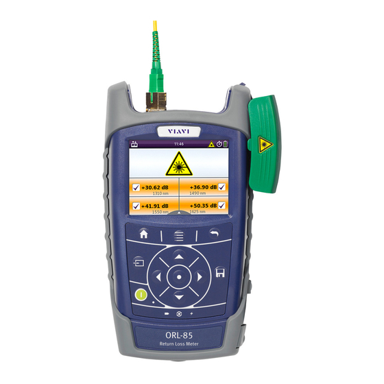
This is particularly likely if the packaging is visibly damaged. If there is damage, do not attempt to operate the instrument. Doing so can cause further damage. In case of damage, please contact your local Viavi sales company. Addresses can be found at www.viavisolutions.com. Recovery following storage/shipping Condensation can occur if a instrument that is stored or shipped at a low temperature is brought into a warm room. - Page 15 ETTING TARTED NPACKING THE INSTRUMENT Instrument overview Fig. 2 Front view ORL-85 Connector interface Test head cover (green for APC connectors) 3.5 inch touchscreen Key pad (operator control panel) Battery compartment and stand (on rear of instrument) USB 2.0 device port (Type Micro-B) USB 2.0 host port (Type A) and external power supply connector Ethernet port (RJ-45) Connector panel...
- Page 16 ETTING TARTED NPACKING THE INSTRUMENT Fig. 4 External power supply connector and communication inter- faces Ethernet port (RJ-45) External power supply connector USB 2.0 host port (Type A) USB 2.0 device port (Type Micro-B) Power supply The following power sources can be used to operate the ORL-85: •...
- Page 17 ETTING TARTED NPACKING THE INSTRUMENT Battery operation WARNING Dangers when handling batteries Handling batteries may be dangerous. Please note the fol- lowing safety instructions. Please note the battery operation safety information in the chapter “Battery operation” on page Replacing batteries Do not replace individual batteries.
- Page 18 ETTING TARTED NPACKING THE INSTRUMENT The battery compartment is on the back of the instrument. Press down the latch to release and to open the lid of the battery compartment. Insert new batteries in the tray or remove the used batteries from the tray and replace all eight with fresh ones.
- Page 19 ETTING TARTED NPACKING THE INSTRUMENT Deep discharge A rechargeable battery that appears to be dead (unit will not turn on even when connected to external power) may well be in a deep discharge state. It can be fully charged with the following charging cycle: Plug in the power cord for 1–1.5 hours.
- Page 20 You will often be able to return used batteries to the place where you purchase new ones. Any dry or rechargeable batteries that you purchased from Viavi can be returned to one of our Service Centers for disposal. Operation from AC power...
-
Page 21: Connecting Optical Cables
The ORL-85 cannot be powered via the USB interface. Connecting optical cables Mounting test adapters Viavi provides a number of test adapters for connecting the ORL-85 to the interface to be tested. You can connect all standard optical connector types to the instrument using these adapters. - Page 22 ETTING TARTED ONNECTING OPTICAL CABLES The PC/APC versions are easily identified by the colors of the name labels on the front: • PC = blue • APC = green NOTE: Only single mode fibers (SMF) may be connected to the ORL-85. To mount the SENKO test adapter: The optical connectors are properly cleaned (see “Cleaning the...
-
Page 23: Basic Operation
ASIC PERATION WITCHING THE INSTRUMENT ON ASIC PERATION Switching the instrument on/off To switch the instrument on: Press the key to switch on the instrument. To switch the instrument off: Press the key to shift the instrument into hibernate mode. –... -
Page 24: Menus And Display Elements
ASIC PERATION ENUS AND DISPLAY ELEMENTS Menus and display elements Home screen Fig. 9 Home screens: Test applications (screen shows PCM version) (1), Management (2), Settings (3) Menu See page Test applications In this menu you can open test applications. Management In this menu you can: •... - Page 25 ASIC PERATION ENUS AND DISPLAY ELEMENTS Test applications Fig. 10 Test applications (screen shows PCM version) Application See page Return Loss To determine the total amount of optical return loss of a fiber link. Powermeter To install and maintain cables and networks with the broadband power meter.
- Page 26 ASIC PERATION ENUS AND DISPLAY ELEMENTS Elements in the top bar Project title Indicates the title of the active project WIFI Indicates that Wifi is installed. It does not indicate an active Wifi connection. Bluetooth Indicates that Bluetooth is installed. It does not indicate an active bluetooth connection.
-
Page 27: Navigating In The Menus
ASIC PERATION AVIGATING IN THE MENUS Navigating in the menus Press the key to open the home screen. Depending on the active project type the Projects tab shows the available test applications or the active Workflow project. Press the key to open the context-sensitive menu. Depending on which application is selected, a different menu opens. -
Page 28: Changing System Settings
ASIC PERATION HANGING YSTEM ETTINGS Changing System Settings In the Settings menu you can change instrument settings, get information and help about the instrument, or update the firmware. To open the Settings menu: The home screen is displayed. Select the tab. - Page 29 ASIC PERATION HANGING YSTEM ETTINGS Icon Function See page WiFi To configure the wireless local area network. The last selected item is displayed in magenta. Bluetooth To configure the Bluetooth interface. Brightness To adjust the display brightness. Help To show device information SW Options Not yet available,...
- Page 30 ASIC PERATION HANGING YSTEM ETTINGS Setting the [Screen-Off] interval When [Screen-Off] is set, the display will switch off after the selected interval without any user action. NOTE: [Screen-Off] is only active when no external power supply is connected. In the menu tap the [More] button,...
- Page 31 ASIC PERATION HANGING YSTEM ETTINGS To set 24-hour or 12-hour time: Tap [Time Format]. Select the desired time format. Setting the Ethernet protocol In the menu tap the [More] button, then tap [Ethernet]. To select the IP mode: Tap the [IP Mode] button.
-
Page 32: Wifi Menu (Optional)
ASIC PERATION I MENU OPTIONAL Resetting to the factory default values NOTE: Setting the factory default values does not affect your stored measurement results. In the menu tap the [More] button, then tap [Factory Reset]. [Yes] to proceed. – or – [No] to cancel. -
Page 33: Installing A Software Option
The latest version of the firmware can be downloaded from the Internet. To find the latest firmware version: Visit the Viavi web site at http://updatemyunit.net. Select your model from the product line. Open the download area and download the latest firmware. -
Page 34: Creating Screenshots
ASIC PERATION REATING SCREENSHOTS Creating screenshots Screenshots can be stored directly on an USB stick. To create a screenshot: Connect a USB stick to one of the USB ports on the right side of the device. symbol is displayed at the top of the screen. Long-press both the and the keys. -
Page 35: Managing Projects
ANAGING PROJECTS REATING A NEW PROJECT ANAGING PROJECTS Stored Measurements are assigned to a project. Therefore a project first has to be created and set to active. As factory setting one Test-Tool project named default is available, which can be edited but not deleted. -
Page 36: Editing A Project
ANAGING PROJECTS DITING A PROJECT Adding a new project: Press the key. The edit menu opens. Tap [Add]. The title edit menu opens. Type in the project title and tap The project is created and displayed in the list. Copying an existing project: Select the project you wish to copy. -
Page 37: Deleting A Project
ANAGING PROJECTS ELETING A PROJECT The changes are immediately effective. Press the button to close the edit menu. Deleting a project Select the project you wish to delete. Press the key and tap [Remove]. [Yes] to permanently delete the project. The project is deleted and removed from the list. -
Page 38: Return Loss Operation
ETURN PERATION ENERAL INFORMATION ETURN PERATION General information In the Return Loss mode the light source (two to four lasers) and the receiver of the ORL-85 are activated. The wavelengths of the Power Meter unit are locked to the wavelengths of the source and can be selected independently. -
Page 39: Pass/Fail Mode
ETURN PERATION AIL MODE Press the key. Tap the [Normalizing] button. Tap the [OK] button. The normalization will be performed and the display will switch to measurement mode. The display shows HIGH db. NOTE: The normalization will be automatically performed for all wavelengths. -
Page 40: Switching On/Off The Laser
ETURN PERATION WITCHING ON OFF THE LASER Switching on/off the laser The instrument is in Return Loss mode. To switch on the laser, tap the [Laser On/Off] field. – or – Press the center key within the arrow keys. – or – Press the key. -
Page 41: Saving Return Loss Test Results
ETURN PERATION AVING ETURN OSS TEST RESULTS The instrument is calibrated manually. To return to the factory calibration mode, tap the [Use Factory Calibration] button in the User Calibration menu. Saving Return Loss test results Before starting a measurement a project must be selected and set to active. - Page 42 ETURN PERATION AVING ETURN OSS TEST RESULTS To edit the label name, tap the field, edit the name and tap [OK]. To change the ID, tap [Decrement or [Increment ID]. Press the key again or tap the [Save] button. The measurement is stored in the current active project. NOTE: If the label/fiber ID is not changed, the data set will be saved under the same title.
-
Page 43: Powermeter Operation
OWERMETER PERATION ENERAL INFORMATION OWERMETER PERATION General information This chapter describes how to use the ORL-85/ORL-85P as a power meter. In Powermeter mode up to two wavelengths can measured simultaneously. Results can be displayed as absolute level in dBm/Watt, relatively to a reference value in dB or as Pass/ Fail indication based on predefined limits. - Page 44 OWERMETER PERATION ETTING AND SELECTING WAVELENGTHS Fig. 14 Measurement display (screen shows the settings menu) Creating and editing wavelengths in the λ table In the [Edit λ Table] menu wavelengths can be added and deleted. Furthermore for each wavelength the reference value and the limit can be defined.
- Page 45 OWERMETER PERATION ETTING AND SELECTING WAVELENGTHS Select the desired wavelength. Press the key and tap the [Delete button. λ] To edit the reference value: The Edit λ Table menu in Powermeter mode is displayed. Select the desired wavelength. Press the key and tap the [Edit Reference] button.
- Page 46 PERATION ETTING AND SELECTING WAVELENGTHS Enabling Auto-λ mode Auto λ is a special feature developed by Viavi that allows you to identify wavelengths automatically (from OLS-XX, MTS-2k/4k/6k OTDR CW-source). To do this, the signal is modulated at a certain frequency (by a light source equipped with Auto λ, such as a Viavi OLS-85), which can be detected by a Viavi ORL-85.
-
Page 47: Selecting And Changing The Power Display Mode
OWERMETER PERATION ELECTING AND CHANGING THE POWER DISPLAY MODE Selecting and changing the power display mode The ORL-85/ORL-85P provides following display modes: • absolute power level in dBm or Watt • power level in dB relatively to a reference value •... -
Page 48: Saving Powermeter Test Results
OWERMETER PERATION AVING OWERMETER TEST RESULTS The actual power level is set as the new reference level. The reference level is displayed underneath the wavelength. Reference power level display mode is activated. NOTE: The reference level is stored for each wavelength and is saved even when the power is off. - Page 49 OWERMETER PERATION AVING OWERMETER TEST RESULTS To edit the label name, tap the field, edit the name and tap [OK]. To change the ID, tap [Decrement or [Increment ID]. Press the key again or tap the [Save] button. The measurement is stored in the current active project. NOTE: When measuring two wavelengths at a time both wavelengths are stored separately.
-
Page 50: Source Operation
The output signals of the light sources may be either continuous wave (CW) or modulated at certain frequencies, i.e. 270 Hz, 1 kHz, or 2 kHz. Viavi power meters (e.g. OLP-3x, OLP-8x, MTS- 2k/4k/6k) are capable of detecting these modulation frequencies. - Page 51 OURCE PERATION ENERAL INFORMATION Display elements Fig. 15 Source operation display, laser off (left) and on. Output port buttons Port not selected / port selected / port selected and laser on Tap to select/deselect. Mode button (modulation) Constant wave > 270 Hz > 1 kHz > 2 kHz > ... Tab button to skip through options.
-
Page 52: Selecting An Output Port And Wavelength
The ORL-85/ORL-85P provides two Auto-λ modes: • Multi-λ: Multi-λ is a proprietary Viavi solution that reduces testing time to a minimum by simultaneously testing at both wavelengths. When activated both wavelength are measured and displayed simultaneously. -
Page 53: Selecting A Modulation Or Auto-Λ Mode
• The wavelength encoding cannot be detected due to interference. • You are measuring the absolute level of a system that does not have wavelength encoding matching Viavi power sources. Selecting a modulation or Auto-λ mode Modulation or Auto-λ mode can be selected by the mode button or via the menu. -
Page 54: Setting The Power Level
OURCE PERATION ETTING THE POWER LEVEL Enabling Multi-λ or Serial-λ (two wavelengths) NOTE: Multi-λ and Serial-λ can only be enabled when two wavelengths are selected. Using the [Mode selection] button: Tap the [Mode selection] button until Auto-λ is displayed. Activate more than one wavelength by tapping. Tap the [Mode selection] button to select Multi-λ... -
Page 55: Switching On/Off The Laser
OURCE PERATION WITCHING ON OFF THE LASER Switching on/off the laser To switch on the laser, tap the [Laser On/Off] button. – or – Press the center key within the arrow keys. – or – Press the key and tap the [Output button. -
Page 56: Measuring Loss With Ource Owermeter
EASURING OSS WITH OURCE OWERMETER ENERAL INFORMATION EASURING OSS WITH OURCE OWERMETER General information The ORL-85 offers three different measurement modes. • Source Mode: The instrument works as a laser source. • Powermeter Mode: The instrument works as an optical power meter. -
Page 57: Viewing Test Results
EASURING OSS WITH OURCE OWERMETER IEWING TEST RESULTS Fig. 16 Performing the measurement (for both directions by switching source and powermeter mode) Connection Source device Powermeter device Fiber system under test Viewing test results The measured loss is displayed in real time. Fig. -
Page 58: Saving Loss Test Results
EASURING OSS WITH OURCE OWERMETER AVING OSS TEST RESULTS Fig. 18 Result overview over two wavelengths Saving Loss test results Before starting a measurement a project must be selected and set to active. Thus, all results are assigned to that project when saved. - Page 59 EASURING OSS WITH OURCE OWERMETER AVING OSS TEST RESULTS Defined label name. Tap field to edit label name. • Probe: Number of already saved probe results. • Powermeter: Number of already saved powermeter results. • PCM: Number of already saved PCM results. •...
-
Page 60: Probe /Pcm Operation
10 P /PCM O ROBE PERATION ENERAL INFORMATION /PCM O ROBE PERATION General information Dirty and/or damaged connectors are often the root cause of optical network problems. The Probe and PCM applications enable industry standard inspection and automated Pass/Fail testing with report generation of optical connectors/adapters in order to ensure industry standard fiber endface quality and cleanliness. -
Page 61: Fmae Series Adapters For The Pcm
10 P /PCM O ROBE PERATION FMAE SERIES ADAPTERS FOR THE Fig. 19 Patch cord microscope components FMAE adapter QuickCapture™ key Focus Control Magnification Control key FMAE series adapters for the PCM SmartClass™ Fiber devices with the PCM use FMAE series adapters to ensure consistent and accurate inspection for a wide variety connectors and applications. - Page 62 10 P /PCM O ROBE PERATION P5000 EATURES AVAILABLE WITH THE IGITAL ROBE provides fast toggling between two microscope magnification levels - low magnification for high level inspection of the fiber endface and high magnification for detailed inspection of the fiber endface.
-
Page 63: Quickcapture™ Key
10 P /PCM O ROBE PERATION ™ UICK APTURE Fig. 21 FBPT series tips for the P5000i Inspection tip Barrel assembly P5000i connection The Probe application requires a P5000i Digital Probe in order to be fully functional (see the list of all accessories in “Digital Probe”... -
Page 64: File Toolbar
10 P /PCM O ROBE PERATION ILE TOOLBAR To display the live view, tap the [Probe] button. File toolbar Saving a picture It is possible to save the frozen picture from the Digital Probe. Press the key. Edit the file name. Tap the [OK] button. - Page 65 10 P /PCM O ROBE PERATION ONFIGURING THE IGITAL ROBE Press the key and tap the [Test] button. – or – Press the QuickCapture™ key on the Digital Probe if the button action is set to Test. When the test procedure terminates, the information shown on the display depends on the current overlay setting: Press the key, and then the...
- Page 66 10 P /PCM O ROBE PERATION ONFIGURING THE IGITAL ROBE NOTE: To return to a Live image, press the QuickCapture™ key or press key and tap the [Live] button to view both the live image and a test result simultaneously. If the test has been passed, the image has a green colored frame.
- Page 67 10 P /PCM O ROBE PERATION ONFIGURING THE IGITAL ROBE Saving the test result in a JPG file Once the test has been performed and the result is displayed on the ORL-85 screen: Click on the key to save a JPG file of the test result in the currently active group on the ORL-85.
-
Page 68: Saving Probe/Pcm Results
10 P /PCM O ROBE PERATION /PCM AVING ROBE RESULTS Press the key. Tap the [Tip] button. Select the tip set on the Digital Probe to connect fiber for inspection and tap on the tip set. More Press the key. Tap the [More] button to view or change the storage location,... - Page 69 10 P /PCM O ROBE PERATION /PCM AVING ROBE RESULTS In live view this action triggers the snapshot. As file name the label prefix defined in the project settings is showed on top of the display. To edit the file name, tap the name, edit it and tap [OK]. To change the ID, tap [Decrement or [Increment ID].
-
Page 70: Data Management
11 D ANAGEMENT AVING RESULTS ANAGEMENT NOTE: Results are always stored under the currently selected (active) project. Thus, to display stored results the desired project must be set to active first (see “Managing projects” on page 35). Saving results Saving results is explained in the descriptions of each application. - Page 71 11 D ANAGEMENT ATA MANAGEMENT OF ETURN OSS AND OWERMETER TESTS Measurement Data of ...Test ggf. Inhalte ür Return Loss anpassen? Fiber ID Test label name λ [nm] Wavelength Loss [dB] measured Loss value Pass/Fail Passed/failed label Limit [dB] Limit value Ref [dBm] Reference value Timestamp...
- Page 72 11 D ANAGEMENT ATA MANAGEMENT OF ETURN OSS AND OWERMETER TESTS NOTE: The selection state of the highlighted entry toggles. The check mark in the first column shows in light grey when an entry is deselected and in dark grey when it is selected. To view test results in full screen: The measurement data overview is displayed.
-
Page 73: Data Management Of Probe And Pcm Tests
11 D ANAGEMENT ATA MANAGEMENT OF ROBE AND TESTS Tap the [Delete Selected] button. The selected test results are deleted. Data management of Probe and PCM tests Recalling stored test results Stored test results are displayed directly from the menu in the Probe/PCM application. - Page 74 11 D ANAGEMENT ATA MANAGEMENT OF ROBE AND TESTS To select one test: To select a test, tap it twice. – or – Press the arrow keys to highlight the test and press the center The check mark shows the selected test. To select multiple tests: Repeat step 1 to select multiple entries.
- Page 75 11 D ANAGEMENT ATA MANAGEMENT OF ROBE AND TESTS To view the previous test result: The selected test result is displayed in full screen. Press the key and tap the [Prev] button. Sorting test results The measurement data overview is displayed. Press the key.
-
Page 76: Exporting Results To Usb
Smart Reporter. Making a report In order to make a report, please download the FiberChekPRO™ or SmartReporter software from the Viavi web site http://updatemyunit.net. Connect your instrument to your PC via the USB port and follow the instructions on the screen. -
Page 77: Maintenance
12 M AINTENANCE LEANING THE TEST PORT AINTENANCE WARNING Dangerous voltage and invisible laser radiation Maintenance or cleaning of the instrument while it is con- nected or operating may damage the instrument or injure you. Make sure that the instrument is switched off and disconnected from all power sources and optical radiation sources before maintenance or cleaning. -
Page 78: Appendix - Referencing Methods
13 A PPENDIX EFERENCING ETHODS EMOTE EFERENCING PPENDIX EFERENCING ETHODS For a fiber loss measurement per length, connection, and splice, the technician must indicate the fiber length, the number of connections, and how many splices are present in the fiber system under test. - Page 79 13 A PPENDIX EFERENCING ETHODS EMOTE EFERENCING Fig. 25 One jumper reference - unidirectional Fig. 26 One jumper reference - bidirectional (switching source and powermeter mode) Connection 1 Connection 4 Laser source output (Transmitter) Powermeter input (Receiver) Source device Powermeter device Measured loss = Δ...
- Page 80 13 A PPENDIX EFERENCING ETHODS EMOTE EFERENCING Two jumper cable reference This reference removes the losses at Connection 1, Connection 2, and Connection 4 from the measurement. Fig. 27 Two jumper reference - unidirectional Fig. 28 Two jumper reference - bidirectional (switching source and powermeter mode) Connection 1 Connection 4...
- Page 81 13 A PPENDIX EFERENCING ETHODS EMOTE EFERENCING This reference removes any loss at the connection between the transmitter of the instrument in source mode and a reference test jumper plus the loss at one connection plus a second reference test jumper (both directions). The loss at the second connection that must be present to measure the fiber system under test will not be referenced out.
- Page 82 13 A PPENDIX EFERENCING ETHODS EMOTE EFERENCING Connection 1 Connection 4 Connection 2 Connection 3 Laser source output (Transmitter) Powermeter input (Receiver) Source device Powermeter device Δ Δ Δ Δ Δ The losses ( ) at Conn. 1 Conn. 2 Conn.
-
Page 83: Remote Control
14 R EMOTE ONTROL EMOTE EFERENCING EMOTE ONTROL Remote Command Documentation Please visit the Viavi web site at http://updatemyunit.net the latest Remote Command Documentation “SCF RC Docs.exe“ (self extracting zip-file). ORL-85/ORL-85P... -
Page 84: Environmental Compliance
The authority to operate this equipment is conditioned by the requirements that no modifications be made to the equipment unless the changes or modifications are expressly approved by Viavi. NOTE: To comply with FCC RF exposure compliance requirements, a separation distance of at least 20 cm must be maintained between the antenna of this device and all persons. - Page 85 15 E NVIRONMENTAL COMPLIANCE EMOTE EFERENCING EU Radio Equipment Directive In accordance with Article 10.8 of the EU Radio Equipment Directive 2014/53/EU, the following table provides information on the frequency bands and the maximum RF transmit power of this product for sale in the EU: Frequency range Channels used Max.
-
Page 86: Specifications
16 S PECIFICATIONS ENERAL SPECIFICATIONS PECIFICATIONS General specifications Fiber inspection Via P5000i Digital Probe with auto Pass/Fail analysis Live image 320 x 240 pixels, 8 bit gray, 10 fps Display High contrast 3.5" TFT color touchscreen Display resolution 0.01 dB / 0.001 µW Measurement units dB, dBm, W Data memory... -
Page 87: Laser Specifications
2) -85 dBm to +15 dBm, -5 °C to +45 °C 3) Overall measurement uncertainty for 1260 to 1650 nm: ±0.80 dB ±0.15 nW 4) With Viavi optical light sources, 800 nm to 1625 nm: level > -60 dBm Laser specifications... -
Page 88: Return Loss Specifications
3) After normalization with singlemode mandrel wrap that has > 70 dB return loss 1 At ambient temperature range -10 °C to +55 °C, ΔT = ±0.3 K 2 Signal coding for automatic power meter wavelength detection. Works only with Viavi power meters e.g. OLP-85 ORL-85/ORL-85P... -
Page 89: Ordering Information
17 O RDERING NFORMATION ORL-85/ORL-85P STAND ALONE UNITS RDERING NFORMATION ORL-85/ORL-85P stand alone units ORL-85 Return Loss Test Set, InGaAs, BN2311/21 1310/1550 nm, SC/APC, FC/APC Return Loss Test Set, InGaAs, BN2311/23 1310/1550/1625 nm, SC/APC, FC/APC Included items Stand-alone units • SmartClass™ Fiber instrument •... - Page 90 NDEX NDEX Device overview 15 Differences between the devices 7 AC line plug adapter 20 Display Activating elements (Source) 51 project 37 Display brightness, adjusting 29 Adjusting Display elements 24 display brightness 29 Display mode (Powermeter) 47 Auto Lambda mode 46 Displaying modulated signals 46 Auto-Lambda Display-off, setting 30...
- Page 91 NDEX date & time 30 display-off 30 On/Off 23 Ethernet protocol 31 Operation Shipping damage 14 Probe/PCM 50 Showing device Information 29 Operation from AC power 20 Source Output port (Source) 52 Auto-Lambda 53 Overview 15 display elements 51 laser on/off 55 modulation 53 Package contents 14 output port 52...
- Page 92 Hazardous materials Viavi avoids or uses with care any hazardous or dangerous material in the manufacturing process or the end product. If the use of a dangerous material cannot be avoided, it is identified in product documentation and clearly labeled on the product itself.
- Page 93 EU Waste Electrical and Electronic Equipment (WEEE) Directive, 2012/ 19/EU, and the EU Battery Directive, 2006/66/EC. Instructions for returning waste equipment and batteries to JDSU can be found in the WEEE section of Viavi's Standards and Policies web page (https://www.viavisolutions.com/en-us/ corporate/legal/policies-standards#sustain).
- Page 94 RODUCT EGULATORY OMPLIANCE ORL-85/ORL-85P...
- Page 95 North America +1 844-468 4284 Viavi product specifications and descriptions in Latin America +1 954 688 5660 this document are subject to change without China +86 21 6859 5260 notice. Germany +49 7121 86 0 © 2019 Operating manual SmartClass™ Fiber Optical Return Loss Meters ORL-85/ORL-85P...
Need help?
Do you have a question about the SmartClass ORL-85 and is the answer not in the manual?
Questions and answers