Table of Contents
Advertisement
Quick Links
Advertisement
Table of Contents

Related Manuals for Viavi SmartClass Fiber OLS-85


Summary of Contents for Viavi SmartClass Fiber OLS-85
- Page 1 OLS-85 SmartClass™ Fiber User’s Guide BN 2313/98.21 2016.01 English...
- Page 2 Please direct all inquiries to your local Viavi sales company. The addres- ses can be found at: www.viavisolutions.com/en-us/contact-sales-expert A description of additional instrument features can be found at: www.viavisolutions.com/en-us/products/network-test-and-certification Notice Every effort was made to ensure that the information in this document was accurate at the time of printing.
-
Page 3: Table Of Contents
ONTENTS ONTENTS ......5 NTRODUCTION OLS-85 Light Sources....... . . 5 Operating manual update . - Page 4 ONTENTS ..... . 47 EMORY ANAGEMENT General information ....... . . 47 Data controls .
-
Page 5: Introduction
NTRODUCTION OLS-85 L IGHT OURCES NTRODUCTION OLS-85 Light Sources The SmartClass™ Fiber OLS-85 light sources are professional, versatile, compact handheld instruments designed for qualification and certification of fiber optic networks. Thoroughly chosen combinations of available wavelengths make the SmartClass™ Fiber OLS-85 light sources the optimum choice for link loss testing and characterization of long-haul, metro, and access telecommunication networks, as well as for data center and local area network testing. - Page 6 NTRODUCTION OLS-85 L IGHT OURCES inspection and automated Pass/Fail testing of optical connectors/adapters in order to ensure industry standard fiber endface quality and cleanliness. You don't need an additional fiber microscope set – simply plug in a P5000i Digital Probe. Report generation –...
-
Page 7: Operating Manual Update
If the operating instructions about features supported by your instrument are missing, please visit the Viavi web site to check if additional information is available. To download the latest user manual: Visit the Viavi web site at http://updatemyunit.net. -
Page 8: Symbols Used In This Operating Manual
NTRODUCTION YMBOLS USED IN THIS OPERATING MANUAL Symbols used in this operating manual Various elements are used in this operating manual to draw attention to special meanings or important points in the text. Symbols and terms used in warnings The following warnings, symbols and terms are used in this document in compliance with the American National Standard ANSI Z535.6-2011: NOTICE... - Page 9 NTRODUCTION YMBOLS USED IN THIS OPERATING MANUAL The following character formats are used in this operating manual: Requirement √ This requirement must be met first; e.g. √ The system is switched on. Instruction ► Follow the instructions given (the numbers indicate the order in which the instructions should be followed);...
-
Page 10: Safety Information
AFETY NFORMATION ARNING SYMBOLS ON THE UNIT AFETY NFORMATION Warning symbols on the unit Warning symbols indicating a potential hazard ► In all cases where the unit is labeled with a warning symbol, the operating manual must be consulted to learn more about the nature of the potential hazard and any action that must be taken. -
Page 11: Laser Safety
AFETY NFORMATION ASER SAFETY Laser safety WARNING Dangerous laser radiation Laser radiation can cause irreparable damage to eyes and skin. ► This device is a Class 1 laser product according to DIN EN 60825-1:2007. ► Always be aware of the hazard level of the instrument to be connected. -
Page 12: Ventilation
AFETY NFORMATION ENTILATION Ventilation NOTICE Insufficient ventilation Insufficient ventilation can damage the instrument or adversely affect its function and safety. ► Ensure adequate ventilation when operating the instrument. PS4 Universal AC/DC Power Supply Safety class The PS4 Universal AC/DC Power Supply unit has a protective isolation that conforms with IEC 60950. - Page 13 AFETY NFORMATION PS4 U AC/DC P NIVERSAL OWER UPPLY NOTICE Condensation Operation in the presence of condensation can damage the PS4 Universal AC/DC Power Supply or adversely affect its function and safety. ► Do not operate the PS4 Universal AC/DC Power Supply if condensation has formed.
-
Page 14: Getting Started
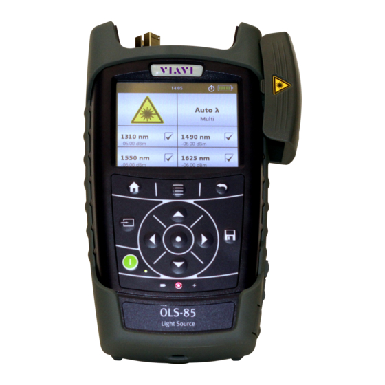
This is particularly likely if the packaging is visibly damaged. If there is damage, do not attempt to operate the instrument. Doing so can cause further damage. In case of damage, please contact your local Viavi sales company. Addresses can be found at www.viavisolutions.com. Recovery following storage/shipping Condensation can occur if a instrument that is stored or shipped at a low temperature is brought into a warm room. - Page 15 ETTING TARTED NPACKING THE INSTRUMENT Instrument overview Fig. 1 Front view OLS-85 Connector interface Test head cover (green for APC- and gray for PC connectors) 3.5 inch touchscreen Key pad (operator control panel) Battery compartment and stand (on rear of instrument) USB 2.0 device port (Type Micro-B) USB 2.0 host port (Type A) and external power supply connector Ethernet port (RJ-45)
- Page 16 ETTING TARTED NPACKING THE INSTRUMENT Connector panel Fig. 2 Connector panel of a single port instrument Optical connector Fig. 3 Connector panel of a dual port instrument Optical connector 1 for single mode Optical connector 2 for multi mode OLS-85...
- Page 17 ETTING TARTED NPACKING THE INSTRUMENT Fig. 4 External power supply connector and communication inter- faces Ethernet port (RJ-45) External power supply connector USB 2.0 host port (Type A) USB 2.0 device port (Type Micro-B) Power supply The following power sources can be used to operate the OLS-85: •...
- Page 18 ETTING TARTED NPACKING THE INSTRUMENT Battery operation WARNING Dangers when handling batteries Handling batteries may be dangerous. Please note the following safety instructions. ► Please note the battery operation safety information in the chapter “Battery operation” on page Replacing batteries ►...
- Page 19 ETTING TARTED NPACKING THE INSTRUMENT Press down the latch lock to release the battery tray. Insert the RBP2 Li-Ion Battery Pack. Close the battery compartment. Press the [E] key to switch on. Recharging the batteries The rechargeable RBP2 Li-Ion Battery Pack is recharged when the PS4 Universal AC/DC Power Supply is being used to power the instrument.
- Page 20 You will often be able to return used batteries to the place where you purchase new ones. Any dry or rechargeable batteries that you purchased from Viavi can be returned to one of our Service Centers for disposal. Operation from AC power NOTICE: Only the PS4 Universal AC/DC Power Supply may be used to operate the OLS-85 from AC power.
-
Page 21: Connecting Optical Cables
The OLS-85 cannot be powered via the USB interface. Connecting optical cables Mounting test adapters Viavi provides a number of test adapters for connecting the OLS-85 to the interface to be tested. You can connect all standard optical connector types to the instrument using these adapters. - Page 22 ETTING TARTED ONNECTING OPTICAL CABLES The OLS-85 connector type must match the cable connector type: • PC: BN 2305/01/11 • APC: BN 2305/21/26/31/36/66 The PC/APC versions are easily identified by the colors of the name labels on the front: • PC = blue •...
- Page 23 ETTING TARTED ONNECTING OPTICAL CABLES To mount the SENKO test adapter: Open the head cover and remove the protective cap (if still mounted). Unscrew the SENKO test adapter and pull it off vertically. Place the SENKO test adapter vertically on the optical connector.
-
Page 24: Basic Operation
ASIC PERATION WITCHING THE INSTRUMENT ON ASIC PERATION Switching the instrument on/off To switch the instrument on: ► Press the [E] key to switch on the instrument. To switch the instrument off: ► Press the [E] key to shift the instrument in hibernate mode. –... -
Page 25: Display Elements
ASIC PERATION ISPLAY ELEMENTS Display elements Fig. 10 Homescreen Link Data Mode Indicates that the project data is summarized. Auto-Off Indicates whether the instrument turns off within a certain time. External power supply The OLS-85 is powered by the external AC adapter when this symbol is shown. -
Page 26: Navigating In The Menus
ASIC PERATION AVIGATING IN THE MENUS Navigating in the menus ► Press the [A] key to open the context-sensitive menu. Depending on which application is in the foreground, a different menu opens. To select a menu item: Press the arrow keys to highlight an item. To confirm, press the center key within the arrow keys. - Page 27 Shows the TCP port used for remote control via Ethernet. Factory Reset Set the instrument parameters and settings to their default values as defined by Viavi. This does not affect any stored measurement results. Manual To show reference information and user assistance for the instrument.
- Page 28 ASIC PERATION ONFIGURING THE INSTRUMENT Adjusting the display brightness Press the [A] key. The menu opens: Tap the [Brightness] button. Type in the desired brightness value. Tap the [OK] button. Selecting a language Press the [A] key and tap the [Settings] button.
- Page 29 ASIC PERATION ONFIGURING THE INSTRUMENT Setting the date Press the [A] key and tap the [Settings] button. Tap the [Date & Time] button. Tap the [Date] button. To change the setting, tap on the [Day], [Month], or [Year] button. Type in the desired value and tap the [OK] button.
-
Page 30: Software Options
Date and time are reset and the stored measurement data remains. Software options To install new software options: Contact your local Viavi sales company or visit the Viavi web site at www.viavisolutions.com. Select a software option from the product line and order it just like an instrument. - Page 31 ASIC PERATION OFTWARE OPTIONS Press the [A] key and tap the [Software Options] button. The menu opens: To start the installation, tap the [Install license via USB stick] button. – or – To type the license key, tap the [Install license via key] button.
-
Page 32: Probe /Pcm Operation
/PCM O ROBE PERATION ENERAL INFORMATION /PCM O ROBE PERATION General information Dirty and/or damaged connectors are often the root cause of optical network problems. The Probe and PCM applications enable industry standard inspection and automated Pass/Fail testing with report generation of optical connectors/adapters in order to ensure industry standard fiber endface quality and cleanliness. -
Page 33: Fmae Series Adapters For The Pcm
/PCM O ROBE PERATION FMAE SERIES ADAPTERS FOR THE Fig. 11 Patch cord microscope components FMAE adapter QuickCapture™ key Focus Control Magnification Control key FMAE series adapters for the PCM SmartClass™ Fiber devices with the PCM use FMAE series adapters to ensure consistent and accurate inspection for a wide variety connectors and applications. - Page 34 /PCM O ROBE PERATION P5000 EATURES AVAILABLE WITH THE IGITAL ROBE provides fast toggling between two microscope magnification levels - low magnification for high level inspection of the fiber endface and high magnification for detailed inspection of the fiber endface. The P5000i Digital Probe kit sold with the OLS-85 contains the standard barrel assembly (FBPP-BAP1), standard patch cord tips, and standard bulkhead tips.
-
Page 35: Quickcapture™ Key
/PCM O ROBE PERATION ™ UICK APTURE P5000i connection The Probe application requires a P5000i Digital Probe in order to be fully functional (see the list of all accessories in “Digital Probe” on page 86). Plug your P5000i into an USB port. Connect the P5000i with the fiber being inspected. -
Page 36: Configuring The Digital Probe
/PCM O ROBE PERATION ONFIGURING THE IGITAL ROBE Configuring the Digital Probe Tap the [Probe] button. Press the [A] key to configure the Digital Probe according to the following description. Brightness settings Set the luminosity manually using the arrow keys. –... - Page 37 /PCM O ROBE PERATION ONFIGURING THE IGITAL ROBE ► Press the [A] key, and then the [Overlay] button to change the overlay view. Repeat the action until the desired view appears. Three views can be displayed: without overlay, with colored edges, and colored edges with a legend.
- Page 38 /PCM O ROBE PERATION ONFIGURING THE IGITAL ROBE Picture selected: Live Test Allows you to launch a (new) test of the connector (see “Launching a test of the connector and fiber end-face” on page Freeze Allows you to freeze the live image and to save it later on the disk.
- Page 39 /PCM O ROBE PERATION ONFIGURING THE IGITAL ROBE Profile Press the [A] key. Tap the [Profile] button. Tap the Profile which will be used for the test of the fiber connector: – E2000: Pass/Fail criteria for precision metal ferrule connec- tors.
-
Page 40: Laser Operation
The output signals of the light sources may be either continuous wave (CW) or modulated at certain frequencies, i.e. 270 Hz, 1 kHz, or 2 kHz. Viavi power meters (e.g. OLP-3x, OLP-8x) are capable of detecting these modulation frequencies. This method... - Page 41 OLS-85 embeds wavelength ID information into the emitted signal(s). This wavelength ID information can be utilized by a compatible Viavi power meter (e.g. OLP-85) for automatic wavelength setup and for simultaneous reception of multiple wavelengths. This minimizes test time and prevents common errors such as incorrect wavelength setting at the optical power meter.
-
Page 42: Selecting A Laser Source
When in one of the Auto λ modes, the OLS-85 embeds wavelength ID information into the emitted signal(s). This wavelength ID information can be utilized by a compatible Viavi power meter (e.g. OLP-85) for automatic wavelength setup and for simultaneous reception of multiple wavelengths. - Page 43 • if the receive level is too low, • the wavelength encoding cannot be detected due to interference, • or if you are measuring the absolute level of a system that does not have wavelength encoding matching Viavi power sources. OLS-85...
-
Page 44: Selecting A Mode
ASER PERATION ELECTING A MODE Selecting a mode Tapping on the [Mode selection] field (see Fig. 15) toggles between the modes as shown in the figure below. There are modes where only a single wavelength can be selected (i.e. CW, 270 Hz, 1 kHz, 2 kHz). -
Page 45: Setting The Power Level
ASER PERATION ETTING THE POWER LEVEL To select the Auto-λ-Multi or Serial mode: If multiple lasers are selected, you have the choice of Multi or Serial mode: • Multi: All selected lasers emit simultaneously. • Serial: The selected lasers emit successively. ►... -
Page 46: Switching On/Off The Laser
ASER PERATION WITCHING ON OFF THE LASER Press the arrow keys to increase or decrease the power level. Press once to change the level in 0.01 dBm steps. – or – Hold down the key to accelerate the step rate. Press the [F] key. -
Page 47: Emory Anagement
EMORY ANAGEMENT ENERAL INFORMATION EMORY ANAGEMENT General information The OLS-85 allows you to save measured values and inspection images in a structured data memory and recall them as required. Data can also be downloaded via the USB interface to a PC for further evaluation. -
Page 48: Selecting The Group To Save Or Display Results
EMORY ANAGEMENT ELECTING THE GROUP TO SAVE OR DISPLAY RESULTS Selecting the group to save or display results To relocate results and images, these can be stored in different groups. The results and images are stored in the group most recently selected. -
Page 49: Displaying Stored Results
EMORY ANAGEMENT ISPLAYING STORED RESULTS Press the [G] key again every time you want to save a an additional result value. The display briefly shows the Fiber ID used. Notes: If the Fiber ID is not changed, the data set will be saved under the same title. -
Page 50: Generating A Report
EMORY ANAGEMENT ENERATING A REPORT Select the measurements you would like to view with the up or down arrow key and press the center key within the arrow keys to set a checkmark. – or – To set a checkmark, tap on the desired measurements. Press the [A] key and tap the [View Selected] button to view... - Page 51 EMORY ANAGEMENT UMMARIZE DATA BY USING THE To link measurement data to a project: √ The Data & Reports menu is displayed. √ The desired project is selected. Press the [A] key. Tap the [More] button. Tap the [Link Data Mode] button.
-
Page 52: Clearing The Memory
EMORY ANAGEMENT LEARING THE MEMORY Clearing the memory Each data set contains the wavelength, the relative power level and reference value or the absolute power level, the threshold set, and the date/time when it was stored. You do not have to clear the entire memory to free up capacity. You can clear individual data or group locations. -
Page 53: Maintenance
AINTENANCE LEANING THE TEST PORT AINTENANCE WARNING Dangerous voltage and invisible laser radiation Maintenance or cleaning of the instrument while it is con- nected or operating may damage the instrument or injure you. ► Make sure that the instrument is switched off and disconnected from all power sources and optical radiation sources before maintenance or cleaning. -
Page 54: Cleaning The Instrument
AINTENANCE LEANING THE INSTRUMENT Cleaning the instrument If the instrument gets dirty through use, you can clean it using a soft cloth moistened with a mild solution of detergent. NOTICE Water and cleaning fluids The instrument may be damaged or destroyed if water or cleaning fluids penetrate it. -
Page 55: Remote Control
EMOTE ONTROL OMMUNICATION INTERFACE EMOTE ONTROL Communication interface The OLS-85 is equipped with a USB 2.0 (Micro-B) device interface for remote control via a PC. In order to operate the OLS-85 via remote control it has to be connected to a PC with a USB cable (see “Accessories”... - Page 56 EMOTE ONTROL OMMUNICATION INTERFACE Fig. 20 Remote control block diagram Selecting an application In order to get to all available applications, to change the currently selected application, and to get to the currently selected application there is a set of application management commands.
- Page 57 EMOTE ONTROL OMMUNICATION INTERFACE Getting access to shared resources On some instruments multiple applications share the same hardware resources. For that reason SmartClass™ Fiber instruments have the simple paradigm: the application which is visible on the GUI always has access to the shared resources. Regarding remote control, an application may not provide full functionality if it is not the currently visible application.
-
Page 58: Command Parameters And Responses
EMOTE ONTROL OMMAND PARAMETERS AND RESPONSES Command parameters and responses The following table lists the parameter and response types used for remote control. <NR1> Integer value. Examples: 23, 90, 0 <NR2> Real number. Examples: 23.45, 1.30 <NR3> Exponential number. Examples: 4.3E-3, -8.9456E8, 123E-5 <NRf>... -
Page 59: Commands
EMOTE ONTROL OMMANDS Commands Overview Generic commands These commands are always used without a prefix. *IDN? *OPT? *RST :APPM:LIST? :APPM:SEL :APPM:SEL? :APPM:VER? :SYST:DATE :SYST:DATE? :SYST:ERR? :SYST:TIME :SYST:TIME? OLS-85... - Page 60 EMOTE ONTROL OMMANDS Probe application/PCM application These commands are used with the prefix :MSCOPE (for Probe application, external microscope) or with the prefix :PCM (for PCM application, built-in microscope). Results :FQM:PERC? :FQM:PERC:MAX? :INSP:PASS? :INSP:PASS:ZONE:A? ... F? :INSP:ZONE:NUMB? Setups :APP:ID:VSBL :APP:ID:VSBL? :AUTO:CNTR :AUTO:CNTR? :CAPT:BTTN:MODE...
- Page 61 EMOTE ONTROL OMMANDS :STOR:GRP:NAME :STOR:GRP:NAME? :STOR:GRP:NAMES? :STOR:NAMES? :STOR:NOTE :STOR:NOTE? :STOR:WR:BUSY? Extended commands :APP:FACT:DEF :MICR:CAL:INFO? :MICR:MODL:NAME? :MICR:SER:NUMB? :MICR:SW:VER? :STOR:ALL:DEL :STOR:DEL :STOR:GRP:CREA :STOR:GRP:DEL :STOR:EVAL:TYPE? :STOR:RD? :STOR:RD:EVAL:XML? :STOR:RD:FMAP? :STOR:RD:IMG:HIGH? :STOR:RD:IMG:HIGH:OVRL? :STOR:RD:IMG:LOW? :STOR:RD:IMG:LOW:OVRL? :STOR:WR OLS-85...
- Page 62 EMOTE ONTROL OMMANDS Laser application These commands are used with the prefix :LASER. Setups :APP:ID:VSBL :APP:ID:VSBL? :AUTO:LMBD :AUTO:LMBD? :AUTO:LMBD:MODE :AUTO:LMBD:MODE? :MEAS:ACT? :SER:MODE:ACT:WLEN :SOUR:ENAB:AVLB:WLEN? :SOUR:ENAB:LSR :SOUR:ENAB:LSR? :SOUR:ENAB:WLEN :SOUR:ENAB:WLEN? :SOUR:ENAB:WLEN:NUMB :SOUR:OUTP:WLEN? :SOUR:POW:WLEN1 ... 4 :SOUR:POW:WLEN1 ... 4? :SOUR:TONE :SOUR:TONE? :SOUR:WLEN:NUMB? :SOUR:WLEN? :STOR:AVLB :STOR:GRP:NAME :STOR:GRP:NAME? :STOR:GRP:NAMES...
- Page 63 EMOTE ONTROL OMMANDS SYSTEM application These commands are used with the prefix :SYSTEM. Setups :APP:ID:VSBL :APP:ID:VSBL? :AUTO:OFF :AUTO:OFF? :DISP:BRGH :DISP:BRGH? :DISP:OFF :DISP:OFF? :ETH:MAC:ADDR? :IP:ADDR? :IP:ADDR:STAT :IP:ADDR:STAT? :IP:GATE :IP:GATE:STAT :IP:GATE:STAT? :IP:MASK :IP:MASK:STAT :IP:MASK:STAT? :IP:MODE :IP:MODE? :LANG :LANG? :OPT:INST:BUSY? :OPT:INST:ERR:LIST? :OPT:INST:LIST? :OPT:ULCK? :STOR:AVLB? Extended commands :APP:FACT:DEF...
- Page 64 EMOTE ONTROL OMMANDS PowerManagement application These commands are used with the prefix :PMGNT. Results :BATT:CAP:PERC? :BATT:TYPE? :POW:SPLY:CON? Setups :STOR:AVLB? Extended commands :APP:FACT:DEF OLS-85...
- Page 65 Parameter type / Response type / Unit / Info *IDN? Returns the unique identification of the instrument. Response type: <STRING_RESPONSE_DATA> e.g. Viavi Solutions Deutschland GmbH, OLS-85/01,A-0106,V03.30 *OPT? Returns the installed software options. *RST Sets the parameters of all running applications to their default values.
- Page 66 EMOTE ONTROL OMMANDS Results for the Probe application/PCM application Command string Parameter type / Response type / Unit / Info :FQM:PERC? Focus quality result. 0 = Not calculated for the image. Response type: <NR1> :FQM:PERC:MAX? Focus quality highwater mark. Highest focus quality value recently observed.
- Page 67 EMOTE ONTROL OMMANDS Setups for the Probe application/PCM application Command string Parameter type / Response type / Unit / Info :APP:ID:VSBL Makes the specified application visible (i.e. brings the specified <STRING> application to foreground). Notes: Full functionality is only available for the active application, so it may be important to know which application is active.
- Page 68 EMOTE ONTROL OMMANDS Command string Parameter type / Response type / Unit / Info :FQM:ENAB? Returns TRUE if the calculated focus quality metric for video frames is enabled. Response type: <BOOLEAN> See :FQM:ENAB command for more information. :FRZE:BUSY? Returns TRUE if an image is captured. After saving the image, the value is changed to FALSE.
- Page 69 EMOTE ONTROL OMMANDS Command string Parameter type / Response type / Unit / Info :INSP:TIP:NAMES? Returns the names of all available tips that match both of the following conditions: • The tip name and the name of an active calibration of the connected Digital Probe must be identical.
- Page 70 EMOTE ONTROL OMMANDS Command string Parameter type / Response type / Unit / Info :OVRL:SHOW Displays or hides the overlay for a tested image. <BOOLEAN> Default: TRUE :OVRL:SHOW? Returns TRUE if the overlay for a tested image is displayed. Response type: <BOOLEAN>...
- Page 71 EMOTE ONTROL OMMANDS Command string Parameter type / Response type / Unit / Info :STOR:GRP:NAMES? This setup contains the names of all available storage groups. The “default” group is always available. :STOR:NAMES? This setup contains the fiber IDs and internal IDs belonging to the group specified by :STOR:GRP:NAME.
- Page 72 EMOTE ONTROL OMMANDS Command string Parameter type / Response type / Unit / Info :STOR:EVAL:TYPE? Returns “1” if a dedicated measurement result specified by group <STRING>, (string1), fiber identifier (string2), and internal identifier (string3) <STRING>, contains a Pass/Fail analysis. Otherwise it returns “0”. <STRING>...
- Page 73 EMOTE ONTROL OMMANDS Command string Parameter type / Response type / Unit / Info :STOR:RD:IMG Returns the contents of a *.lm.jpg (“lm.jpg” = “low magnification.jpg”) :LOW? file specified by group (string1), fiber identifier (string2), and internal <STRING>, identifier (string3). <STRING>, Special format: “#h:14823,696e7072cdcc”...
- Page 74 EMOTE ONTROL OMMANDS Setups for the Laser application Command string Parameter type / Response type / Unit / Info :APP:ID:VSBL Makes the specified application visible (i.e. brings the specified <STRING> application to foreground). Notes: Full functionality is only available for the active application, so it may be important to know which application is active.
- Page 75 EMOTE ONTROL OMMANDS Command string Parameter type / Response type / Unit / Info :SER:MODE:ACT Returns the wavelength of the active laser source, if the auto lambda :WLEN <NR1> mode is active. Valid range: 800 to 1700 Default: :SOUR:ENAB:AVLB Returns an array of boolean values indicating if a laser with a particular :WLEN? wavelength can be enabled.
- Page 76 EMOTE ONTROL OMMANDS Command string Parameter type / Response type / Unit / Info :SOUR:TONE <NR1> Sets the modulation frequency. Notes: The selected value is written to the laser sources if Auto λ is disabled. Valid values: 0: CW 1: 270 Hz 2: 1 kHz 3: 2 kHz Default:...
- Page 77 EMOTE ONTROL OMMANDS Setups for the SYSTEM application Command string Parameter type / Response type / Unit / Info :APP:ID:VSBL Makes the specified application visible (i.e. brings the specified <STRING> application to foreground). Notes: Full functionality is only available for the active application, so it may be important to know which application is active.
- Page 78 EMOTE ONTROL OMMANDS Command string Parameter type / Response type / Unit / Info :DISP:OFF <NR1> In order to save power, the display switches off automatically after a predefined time of inactivity. If an external power supply is connected, the display doesn’t switch off. Valid values: 0 (15 sec) 1 (30 sec)
- Page 79 EMOTE ONTROL OMMANDS Command string Parameter type / Response type / Unit / Info :IP:MASK? Returns the IP mask which is currently valid for the instrument. In static mode, this setup corresponds to IP:MASK:STAT; in DHCP mode, it is provided by the DHCP server. This setup is read-only.
- Page 80 EMOTE ONTROL OMMANDS Command string Parameter type / Response type / Unit / Info :OPT:INST:ERR:LIST? Returns a list of errors that occurred during installation of a license via USB flash drive or a key. List is cleared at the beginning of each installation.
- Page 81 EMOTE ONTROL OMMANDS Results for the PowerManagement application Command string Parameter type / Response type / Unit / Info :BATT:CAP:PERC? Returns the remaining battery capacity in percent. If :BATT:TYPE == NOBATT 0 is returned. :BATT:TYPE? The instrument can work without an internal battery (NOBATT), with a rechargeable Lithium Ion battery (LIION), or with standard dry-cell batteries (DRYCELL).
-
Page 82: Error Messages
EMOTE ONTROL RROR MESSAGES Error messages Processing the program messages can cause the following error messages: • 0,“No error” • -310,“System error” • -350,“Queue overflow” • -360,“Communication error” • -100,“Command error” • -101,“Invalid character” • -108,“Parameter not allowed” • -109,“Missing parameter” •... -
Page 83: Specifications
10 S PECIFICATIONS OLS-85 SPECIFICATIONS PECIFICATIONS OLS-85 specifications Laser safety IEC 60825-1:2007 Laser classification CLASS 1 LASER PRODUCT Power setting resolution 0.01 dB Tracking error ± 1 dB Wavelengths BN 2313/01 1310/1550 nm , PC BN 2313/05 850/1300 nm MM & 1310/1550 nm SM , PC BN 2313/06 1310/1490/1550/1625 nm... - Page 84 1 CW signal, T = 23 °C ±3 K, including connector, depending on quality of connector applied to the OLS 2 At ambient temperature range -10 °C to +55 °C, ΔT = ±0.3 K 3 Signal coding for automatic power meter wavelength detection. Works only with Viavi power meters e.g. OLP-85 OLS-85...
-
Page 85: General Specifications
10 S PECIFICATIONS ENERAL SPECIFICATIONS General specifications Fiber inspection Via P5000i Digital Probe with auto Pass/ Fail analysis Live image 320 x 240 pixels, 8 bit gray, 10 fps Display High contrast 3.5" TFT color touchscreen Display resolution 0.01 dB / 0.001 µW Measurement units dB, dBm, W Data memory... -
Page 86: Ordering Information
11 O RDERING NFORMATION OLS-85 O PTICAL ASER OURCE RDERING NFORMATION OLS-85 Optical Laser Source 1310/1550 nm, PC universal adapter BN 2313/01 1310/1550/1625 nm, APC universal adapter BN 2313/22 1310/1490/1550/1625 nm, PC universal adapter BN 2313/06 1310/1490/1550/1625 nm, APC universal adapter BN 2313/26 850/1300 nm MM, 1310/1550 nm SM, PC universal BN 2313/05... - Page 87 NDEX NDEX AC line plug adapter 20 Factory default 29 Auto Lambda mode 44 Firmware update 30 Auto-Off 25 Laser safety 11 Batteries Link Data Mode 25, 41, 50 Danger 18 Recharging 19 Replacing 18 Menu Tips 19 Configuration 26 Battery operation 11 Menu navigation 26 Cables, connecting 21...
- Page 88 NDEX Remote commands Error messages 82 Generic commands 65 PowerManagement 64, 81 PowerMeter 74 Probe/PCM 60, 66, 67, 71 System 63, 77, 80 Results PowerManagement 81 Probe/PCM 66 RoHS 91 Saving results 48 Setups 74, 81 Probe/PCM 67 System 77 Shipping damage 14 Specifications General 85...
- Page 89 Hazardous materials Viavi avoids or uses with care any hazardous or dangerous material in the manufacturing process or the end product. If the use of a dangerous material cannot be avoided, it is identified in product documentation and clearly labeled on the product itself.
- Page 90 If you would like specific information about the Viavi Environmental Management Program, please contact us at: If you would like specific information about the Viavi Environmental Management Program, please contact us at www.viavisolutions.com. The following page provides information with regard to the location of restricted hazardous substances within this equipment according to Chinese requirements.
- Page 91 RoHS (Additional Information required for the Chinese Market only) RoHS (Component) (Pb) (Hg) (Cd) (PBB) (PBDE) (Main Product) (PCB Assemblies) (Internal wiring) (Display) (Keyboard) (Plastic case parts) (Accessories) SJ/T11363-2006 SJ/T11363-2006 OLS-85...
- Page 92 OLS-85...
- Page 94 North America +1 844-468 4284 Viavi product specifications and descriptions in Latin America +1 954 688 5660 this document are subject to change without China +86 21 6859 5260 notice. Germany +49 7121 86 0 © 2016.01 User‘s Guide SmartClass™ Fiber OLS-85...
Need help?
Do you have a question about the SmartClass Fiber OLS-85 and is the answer not in the manual?
Questions and answers