
Related Manuals for ICP DAS USA ACS-20B-MRTU


Summary of Contents for ICP DAS USA ACS-20B-MRTU
- Page 1 User Manual Version 1.1 Feb 2021 ACS-20B(W)-MRTU No-touch Infrared Sensor Switch Written by Bruce Hsu Edited by Kalia Huang...
-
Page 2: Table Of Contents
Table of Contents Introduction ......................... 6 1.1 Features .......................... 7 Hardware ..........................8 2.1 Specifications ........................8 2.2 Appearance ........................9 2.3 Pin assignments ......................10 2.4 LED Indicators ......................11 Configured by Hardware ....................12 3.1 Relay Hold Time ......................12 3.2 Toggle Switch Mode ...................... - Page 3 5.2 Modbus FC100 Commands ..................26 5.2.1 Sub-FC00 (0x00): Get the Module Name ............... 27 5.2.2 Sub-FC04 (0x04): Set the Modbus Unit ID (Net ID)..........28 5.2.3 Sub-FC05 (0x05): Get Communication Settings ............ 29 5.2.4 Sub-FC06 (0x06): Set Communication Settings ............. 30 5.2.5 Sub-FC07 (0x07): Read Current Communication Settings ........
- Page 4 Appendix B. Revision History ....................63 ACS-20-MRTU User Manual Version 1.1 Page: Copyright © 2020 ICP DAS Co., Ltd. All Rights Reserved E-mail: service@icpdas.com...
- Page 5 Important Information Warranty All products manufactured by ICP DAS are under warranty regarding defective materials for a period of one year, beginning from the date of delivery to the original purchaser. Warning ICP DAS assumes no liability for any damage resulting from the use of this product.ICP DAS reserves the right to change this manual at any time without notice.
-
Page 6: Introduction
1. Introduction Figure 1-1 ACS-20B(W)-MRTU application architecture The No-touch Infrared Sensor Switch from ICP DAS can be used to open a door using palm induction, which makes it more convenient when entering or exiting a room or building. The inductive distance and the delay time for door opening are adjustable, and has red and blue indicator lights to show the status of the switch. -
Page 7: Features
1.1 Features ◼ [ACS-20B-MRTU / ACS-20W-MRTU] ◆ Special infrared code to against interference ◆ Multiple operating modes: Sensing/Standby, Lock, Toggle Switch. ◆ Provides 8 locked periods each day ◆... -
Page 8: Hardware
2. Hardware 2.1 Specifications Table 2-1: Specification Table Model ACS-20B-MRTU ACS-20W-MRTU IR Interface IR Output Ch. IR Input Ch. COM Ports Ports RS-485 (DATA+, DATA-) Baud Rate (bps) 9600, 19200, 38400, 57600, 115200 Protocol Modbus RTU (slave) LED Indicator Red (Standby); Blue (Sensing) [can be inverted]... -
Page 9: Appearance
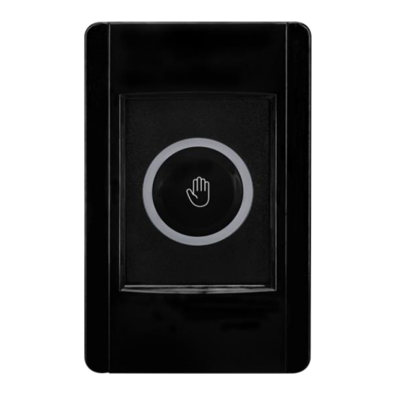
2.2 Appearance Figure 2-1: ACS-20B-MRTU. Figure 2-2: ACS-20W-MRTU ACS-20B(W)-MRTU User Manual Version 1.1 Page: Copyright © 2021 ICP DAS Co., Ltd. All Rights Reserved E-mail: service@icpdas.com... -
Page 10: Pin Assignments
2.3 Pin assignments ◼ Terminals Figure 2-3: ACS-20B(W)-MRTU terminals ◼ Cables Table 2-2: Cables for ACS-20B(W)-MRTU terminal Cables Picture Model. Description Interface +Vs (Red) (+10~+30VDC) CA-014 Power GND (Black)- NO (Blue) CA-012 Relay COM (White) NC (Green) DATA+ (Green) CA-019 RS-485 DATA- (黃) ACS-20B(W)-MRTU User Manual... -
Page 11: Led Indicators
2.4 LED Indicators There are circular red and blue led indicators on the ACS-20B/W-MRTU to show different operating states. The meanings of these states are described in Table 2-3. Figure 2-4: Red/Blue LED indicators of ACS-20B(W)-MRTU Table 2-3: Red/Blue LED indicators corresponding to module status Circular LED Indicator ACS-20B(W)-MRTU Status Red LED ON (NC &... -
Page 12: Configured By Hardware
3. Configured by Hardware 3.1 Relay Hold Time Relay hold time (off-delay time) after IR sensing can be set by the scale position “0~C” of the rotary switch (figure 3-1) as shown in table 3-1. Figure 3-1: Scale 0~C of rotary switch for relay hold time Table 3-1: relay hold time to the scale of the rotary switch scale Relay hold time (sec) -
Page 13: Toggle Switch Mode
3.2 Toggle Switch Mode Rotate the rotary switch to the scale ‘D’ to be in the hardware Toggle Switch Mode. In this mode, sense the ACS-20B(W)-MRTU by hand once, the circular red LED is changed to blue (Relay: NO & COM contact). Then, sense the ACS-20B(W)-MRTU by hand once again, the blue LED will be changed back to red. -
Page 14: Restore Default Communication Settings
3.4 Restore Default Communication Settings Rotate the rotary switch to the scale ‘E’. Power cycle the module to restore the default serial communication (Table ). Figure 3-4: Rotate the rotary switch to ‘E’ scale for default communication. Table 3-2: relay hold time to the scale of the rotary s Item Default value Baud Rate... -
Page 15: Configured By Software
Microsoft Windows OS. Users can download the ACS-20 Utility from: ACS-20 Utility (ACS20_Util_Setup_v#i#i#i#.zip) https://www.icpdas.com/en/download/show.php?num=3154&model=ACS-20B-MRTU If the .NET Framework 4.5 is not available on the Microsoft OS, the setup package will download and install the redistribution automatically. The redistribution package can also be downloaded from the following link: https://www.microsoft.com/en-US/download/details.aspx?id=30653... -
Page 16: Serial Communication
4.2 Serial Communication The initial window of the ACS-20 utility is shown in the left of figure 4-1. Select the COM port of the host PC and the communication parameters of ACS-20B(W)-MRTU. Go to the main configuration window by clicking the “Connect” button. Figure 4-1: Configuration window for ACS-20B(W)-MRTU. -
Page 17: Test Locked Mode
Figure 4-3: Set communication settings. 4.3 Test Locked Mode In the “IR Sensing” section of the utility, click “Lock” and “Unlock” button (figure 4-4) to test the locked mode. IR sensing function is disabled in this mode. Refer to chapter 5 for related Modbus command. -
Page 18: Set Toggle Mode
Figure 4-5: Set relay hold time. 4.5 Set Toggle Mode In the “IR Sensing” section of the utility, click the “Set” button after checking or unchecking the “Toggle Mode” checkbox as shown in figure 4-6. Refer to chapter 5 for related Modbus register and command. -
Page 19: Set Rtc
Figure 4-7: Set inversion of Red/Blue LED. 4.7 Set RTC There is built-in RTC (Real Time Clock) in ACS-20B(W)-MRTU. One RTC Time (Year/Month/Day, Hour:Minute:Second) is recorded when IR sensing by palm of hand. In the “Set RTC” section (figure 4-8) of the utility, the time following the “System Time” radio button is the host system time. -
Page 20: Set Ir Sensing Record Mode
4.8 Set IR Sensing Record Mode The “Record Mode” in the “IR Sensing Records in Storage” section (figure 4-9) is for setting the storage mode when the storage is full. There are two modes: Mode 0 (Store from start): (default) Clear all records and store from start. Mode 1 (Discard the latest): Discard new data and keep 1600 records of old data. -
Page 21: Access All Settings
(1) Check/Uncheck “Enabled Locked Periods Function” checkbox to enable/disable this function. (2) Click the “Locked Periods” combobox to select 8 periods (0 ~ 7) for setting. The “End Time” should be more than the “Start Time”. (3) Click “Enable Every Day Mode” or “Enable Week Day Mode” radio button for “Every Day Mode”... -
Page 22: Configuration File
4.11 Configuration File All settings in the utility can be saved to a configuration file by clicking Menu [File]=>[Save Settings to File(*.dat)] where the file extension is dat. Load all setting from a configuration file by clicking Menu [File]=>[Load Settings from File(*.dat)] Figure 4-12: Access configuration file. -
Page 23: Modbus Command
5. Modbus Command The following Function Code commands () are provided for a Modbus master to configure ACS-20B(W)-MRTU. FC3, FC4, and FC6 are the standard Modbus commands for Modbus masters to access the Modbus registers. Sub-FC commands of FC100 are manufacturer assigned commands for parameter settings on the module. -
Page 24: Modbus Register Table
Modbus Register Table Please refer to table 5-2 and table 5-3 for the Modbus Input Registers (3xxxx) and Modbus Holding Registers (4xxxx). Settings written to the Modbus holding registers are all volatile for ACS-20B(W)-MRTU. The values will go back to the default or previous ones after power cycling. The settings can be kept (non-volatile) by the FC100 commands in section 5.2. -
Page 25: Modbus Holding Registers
5.1.2 Modbus Holding Registers The Modbus Holding Registers are listed in Table 5-3. The access is read and write. Write values to the holding registers can change settings immediately but restore to previous ones after power cycling the module. Table 5-3: Modbus Holding Registers (4xxxx) Address Description (0-index) -
Page 26: Modbus Fc100 Commands
Modbus FC100 Commands This section describes all sub function calls (sub-FC) of FC100 (0x64) for the settings on ACS-20B(W)-MRTU. All sub-FCs are listed in table 5-4. All setting values are non-volatile (effective after power-cycling the module). In the following sections, Modbus requests and responses are listed without CRC16 bytes. -
Page 27: Sub-Fc00 (0X00): Get The Module Name
5.2.1 Sub-FC00 (0x00): Get the Module Name The request/response for getting the module name is listed in table 5-5 and table 5-6. Table 5-5: FC100-Sub-FC00 Request Byte Description Size Value order Address 1 Byte 1 ~ 247 (Net ID) 1 Byte 0x64 Sub-FC 1 Byte... -
Page 28: Sub-Fc04 (0X04): Set The Modbus Unit Id (Net Id)
5.2.2 Sub-FC04 (0x04): Set the Modbus Unit ID (Net ID) Table 5-7: FC100-Sub-FC04 Request Byte Description Size Value order Address 1 Byte 1 ~ 247 (Net ID) 1 Byte 0x64 Sub-FC 1 Byte 0x04 1 Byte 1 ~ 247 (Net ID) Address [reserved] 1 Byte... -
Page 29: Sub-Fc05 (0X05): Get Communication Settings
5.2.3 Sub-FC05 (0x05): Get Communication Settings Table 5-9: FC100-Sub-FC05 Request Byte Description Size Value order Address 1 Byte 1 ~ 247 (Net ID) 1 Byte 0x64 Sub-FC 1 Byte 0x05 reserved 1 Byte 0x00 Table 5-10: FC100-Sub-FC05 Response Byte Description Size Value order... -
Page 30: Sub-Fc06 (0X06): Set Communication Settings
5.2.4 Sub-FC06 (0x06): Set Communication Settings Table 5-11: FC100-Sub-FC06 Request Byte Description Size Value order Address 1 Byte 1 ~ 247 (Net ID) 1 Byte 0x64 Sub-FC 1 Byte 0x05 New NetID 1 Byte 1 ~ 247 (Net ID) of the module Baud rate 1 Byte 6 ~ 10 (baud rate index) -
Page 31: Sub-Fc07 (0X07): Read Current Communication Settings
5.2.5 Sub-FC07 (0x07): Read Current Communication Settings The settings read from Sub-FC05 is the settings by Sub-FC06 if the Byte 09 [Change Setting] of Sub-FC06 is 0 (The settings are effective after power-cycling). Sun-FC07 reads the settings before power-cycling the module. Table 5-13: FC100-Sub-FC07 Request Byte Description... -
Page 32: Sub-Fc08 (0X08): Get Modbus Response Delay
5.2.6 Sub-FC08 (0x08): Get Modbus Response Delay Table 5-15: FC100-Sub-FC08 Request Byte Description Size Value order Address 1 Byte 1 ~ 247 (Net ID) 1 Byte 0x64 Sub-FC 1 Byte 0x08 Table 5-16: FC100-Sub-FC08 Response Byte Description Size Value order Address 1 Byte 1 ~ 247 (Net ID) -
Page 33: Sub-Fc09 (0X09): Set Modbus Response Delay
5.2.7 Sub-FC09 (0x09): Set Modbus Response Delay Table 5-17: FC100-Sub-FC09 Request Byte Description Size Value order Address 1 Byte 1 ~ 247 (Net ID) 1 Byte 0x64 Sub-FC 1 Byte 0x09 Modbus 1 Byte 0 ~ 30 ms (default: 1ms) Response Delay Table 5-18: FC100-Sub-FC09 Response... -
Page 34: Sub-Fc32 (0X20): Get Firmware Version
5.2.8 Sub-FC32 (0x20): Get Firmware Version Table 5-19: FC100-Sub-FC32 Request Byte Description Size Value order Address 1 Byte 1 ~ 247 (Net ID) 1 Byte 0x64 Sub-FC 1 Byte 0x20 Table 5-20: FC100-Sub-FC32 Response Byte Description Size Value order Address 1 Byte 1 ~ 247 (Net ID) 1 Byte... -
Page 35: Sub-Fc33 (0X21): Get Firmware Date
5.2.9 Sub-FC33 (0x21): Get Firmware Date Table 5-21: FC100-Sub-FC33 Request Byte Description Size Value order Address 1 Byte 1 ~ 247 (Net ID) 1 Byte 0x64 Sub-FC 1 Byte 0x21 Table 5-22: FC100-Sub-FC33 Response Byte Description Size Value order Address 1 Byte 1 ~ 247 (Net ID) 1 Byte... -
Page 36: Sub-Fc34 (0X22): Get Stored Quantity Of Ir Sensing Records
5.2.10 Sub-FC34 (0x22): Get Stored Quantity of IR Sensing Records Table 5-23: FC100-Sub-FC34 Request Byte Description Size Value order Address 1 Byte 1 ~ 247 (Net ID) 1 Byte 0x64 Sub-FC 1 Byte 0x22 Table 5-24: FC100-Sub-FC34 Response Byte Description Size Value order... -
Page 37: Sub-Fc35 (0X23): Clear All Stored Ir Sensing Records
5.2.11 Sub-FC35 (0x23): Clear All Stored IR Sensing Records Table 5-25: FC100-Sub-FC35 Request Byte Description Size Value order Address 1 Byte 1 ~ 247 (Net ID) 1 Byte 0x64 Sub-FC 1 Byte 0x23 Reserved 1 Byte 0x00 Table 5-26: FC100-Sub-FC35 Response Byte Description Size... -
Page 38: Sub-Fc39 (0X27): Get Rtc Time
5.2.12 Sub-FC39 (0x27): Get RTC Time Table 5-27: FC100-Sub-FC39 Request Byte Description Size Value order Address 1 Byte 1 ~ 247 (Net ID) 1 Byte 0x64 Sub-FC 1 Byte 0x27 Table 5-28: FC100-Sub-FC39 Response Byte Description Size Value order Address 1 Byte 1 ~ 247 (Net ID) 1 Byte... -
Page 39: Sub-Fc40(0X28): Set Rtc Time
5.2.13 Sub-FC40(0x28): Set RTC Time Table 5-29: FC100-Sub-FC40 Request Byte Description Size Value order Address 1 Byte 1 ~ 247 (Net ID) 1 Byte 0x64 Sub-FC 1 Byte 0x28 Year_MSB 1 Byte High byte of AD Year, e.g. 07h of 07E5h (2021) Year_LSB 1 Byte Low byte of AD Year,... -
Page 40: Sub-Fc41(0X29): Get Ir Sensing Record Data
5.2.14 Sub-FC41(0x29): Get IR Sensing Record Data Table 5-31: FC100-Sub-FC41 Request Byte Description Size Value order Address 1 Byte 1 ~ 247 (Net ID) 1 Byte 0x64 Sub-FC 1 Byte 0x29 Number of 1 Byte 1 ~ 31, read number of records. records The size of 1 record is 8 bytes. -
Page 41: Sub-Fc42(0X2A): Get Ir Sensing Record Mode
5.2.15 Sub-FC42(0x2A): Get IR Sensing Record Mode Table 5-33: FC100-Sub-FC42 Request Byte Description Size Value order Address 1 Byte 1 ~ 247 (Net ID) 1 Byte 0x64 Sub-FC 1 Byte 0x2A Table 5-34: FC100-Sub-FC42 Response Byte Description Size Value order Address 1 Byte 1 ~ 247 (Net ID) -
Page 42: Sub-Fc43(0X2B): Set Ir Sensing Record Mode
5.2.16 Sub-FC43(0x2B): Set IR Sensing Record Mode Table 5-35: FC100-Sub-FC43 Request Byte Description Size Value order Address 1 Byte 1 ~ 247 (Net ID) 1 Byte 0x64 Sub-FC 1 Byte 0x2B Record 1 Byte The way of storing records when storage full: mode 0=>... -
Page 43: Sub-Fc44(0X2C): Get Inverted Red/Blue Led Status
5.2.17 Sub-FC44(0x2C): Get Inverted Red/Blue LED Status Table 5-37: FC100-Sub-FC44 Request Byte Description Size Value order Address 1 Byte 1 ~ 247 (Net ID) 1 Byte 0x64 Sub-FC 1 Byte 0x2C Table 5-38: FC100-Sub-FC44 Response Byte Description Size Value order Address 1 Byte 1 ~ 247 (Net ID) -
Page 44: Sub-Fc45(0X2D): Set Inverted Red/Blue Led Status
5.2.18 Sub-FC45(0x2D): Set Inverted Red/Blue LED Status Table 5-39: FC100-Sub-FC45 Request Byte Description Size Value order Address 1 Byte 1 ~ 247 (Net ID) 1 Byte 0x64 Sub-FC 1 Byte 0x2D Inverted 1 Byte 0 => default Red(Standby) / Blue(Sensing); Red/Blue LED 1 =>... -
Page 45: Sub-Fc46(0X2E): Get Relay Hold Time
5.2.19 Sub-FC46(0x2E): Get Relay Hold Time Table 5-41: FC100-Sub-FC46 Request Byte Description Size Value order Address 1 Byte 1 ~ 247 (Net ID) 1 Byte 0x64 Sub-FC 1 Byte 0x2E Table 5-42: FC100-Sub-FC46 Response Byte Description Size Value order Address 1 Byte 1 ~ 247 (Net ID) 1 Byte... -
Page 46: Sub-Fc47(0X2F): Set Relay Hold Time
5.2.20 Sub-FC47(0x2F): Set Relay Hold Time Table 5-43: FC100-Sub-FC47 Request Byte Description Size Value order Address 1 Byte 1 ~ 247 (Net ID) 1 Byte 0x64 Sub-FC 1 Byte 0x2F Relay hold 1 Byte High byte of relay hold time (500~20,000ms) time MSB e.g. -
Page 47: Sub-Fc64(0X40): Get Locked Mode
5.2.21 Sub-FC64(0x40): Get Locked Mode Table 5-45: FC100-Sub-FC64 Request Byte Description Size Value order Address 1 Byte 1 ~ 247 (Net ID) 1 Byte 0x64 Sub-FC 1 Byte 0x40 Table 5-46: FC100-Sub-FC64 Response Byte Description Size Value order Address 1 Byte 1 ~ 247 (Net ID) 1 Byte 0x64... -
Page 48: Sub-Fc65(0X41): Set Locked Mode
5.2.22 Sub-FC65(0x41): Set Locked Mode Table 5-47: FC100-Sub-FC65 Request Byte Description Size Value order Address 1 Byte 1 ~ 247 (Net ID) 1 Byte 0x64 Sub-FC 1 Byte 0x41 Locked mode 1 Byte 0x00 => disabled (unlocked) 0x01 => enabled (locked) Table 5-48: FC100-Sub-FC65 Response Byte Description... -
Page 49: Sub-Fc66(0X42): Get Day Mode Of Locked Periods
5.2.23 Sub-FC66(0x42): Get Day Mode of Locked Periods Table 5-49: FC100-Sub-FC66 Request Byte Description Size Value order Address 1 Byte 1 ~ 247 (Net ID) 1 Byte 0x64 Sub-FC 1 Byte 0x42 Table 5-50: FC100-Sub-FC66 Response Byte Description Size Value order Address 1 Byte... -
Page 50: Sub-Fc67(0X43): Set Day Mode Of Locked Periods
5.2.24 Sub-FC67(0x43): Set Day Mode of Locked Periods Table 5-51: FC100-Sub-FC67 Request Byte Description Size Value order Address 1 Byte 1 ~ 247 (Net ID) 1 Byte 0x64 Sub-FC 1 Byte 0x43 Day mode 1 Byte 0x00 => Every day mode (default) 0x01 =>... -
Page 51: Sub-Fc68(0X44): Get Enabled State Of Locked Periods
5.2.25 Sub-FC68(0x44): Get Enabled State of Locked Periods This command gets the enable/disable status of the 8 locked periods in a day by one byte with 8 bits (b7~b0=>P8~P1) where bit value = 1 means enabled and bit value = 0 disabled. -
Page 52: Sub-Fc69(0X45): Set Enabled State Of Locked Periods
5.2.26 Sub-FC69(0x45): Set Enabled State of Locked Periods This command gets the enable/disable status of the 8 locked periods in a day by one byte with 8 bits (b7~b0=>P8~P1) where bit value = 1 means enabled and bit value = 0 disabled. -
Page 53: Sub-Fc70(0X46): Get 8 Locked Periods
5.2.27 Sub-FC70(0x46): Get 8 Locked Periods This command gets 8 locked periods in a day from module. One locked period composed of Start Time and End Time. The End Time should be late after the Start Time. Table 5-57: FC100-Sub-FC70 Request Byte Description Size... -
Page 54: Sub-Fc71(0X47): Set 8 Locked Periods
5.2.28 Sub-FC71(0x47): Set 8 Locked Periods This command sets 8 locked periods in a day to module. One locked period composed of Start Time and End Time. The End Time should be late after the Start Time. Table 5-59: FC100-Sub-FC71 Request Byte Description Size... -
Page 55: Sub-Fc72(0X48): Get Enabled State Of Locked Period Function
5.2.29 Sub-FC72(0x48): Get Enabled State of Locked Period Function Table 5-61: FC100-Sub-FC72 Request Byte Description Size Value order Address 1 Byte 1 ~ 247 (Net ID) 1 Byte 0x64 Sub-FC 1 Byte 0x48 Table 5-62: FC100-Sub-FC72 Response Byte Description Size Value order Address... -
Page 56: Sub-Fc73(0X49): Set Enabled State Of Locked Period Function
5.2.30 Sub-FC73(0x49): Set Enabled State of Locked Period Function Note: Settings of Sub-FC66~ 71 are effective when this function is enabled. Table 5-63: FC100-Sub-FC73 Request Byte Description Size Value order Address 1 Byte 1 ~ 247 (Net ID) 1 Byte 0x64 Sub-FC 1 Byte... -
Page 57: Sub-Fc76(0X4C): Get Scale Value Of Rotary Switch
5.2.31 Sub-FC76(0x4C): Get Scale Value of Rotary Switch Note: Settings of Sub-FC66~ 71 are effective when this function is enabled. Table 5-65: FC100-Sub-FC76 Request Byte Description Size Value order Address 1 Byte 1 ~ 247 (Net ID) 1 Byte 0x64 Sub-FC 1 Byte 0x4C... -
Page 58: Sub-Fc77(0X4D): Get Toggle Mode
5.2.32 Sub-FC77(0x4D): Get Toggle Mode Table 5-67: FC100-Sub-FC77 Request Byte Description Size Value order Address 1 Byte 1 ~ 247 (Net ID) 1 Byte 0x64 Sub-FC 1 Byte 0x4D Table 5-68: FC100-Sub-FC77 Response Byte Description Size Value order Address 1 Byte 1 ~ 247 (Net ID) 1 Byte 0x64... -
Page 59: Sub-Fc78(0X4E): Set Toggle Mode
5.2.33 Sub-FC78(0x4E): Set Toggle Mode Table 5-69: FC100-Sub-FC78 Request Byte Description Size Value order Address 1 Byte 1 ~ 247 (Net ID) 1 Byte 0x64 Sub-FC 1 Byte 0x4E Toggle mode 1 Byte 0x00 => disabled (default) 0x01 => enabled Table 5-70: FC100-Sub-FC78 Response Byte Description... -
Page 60: Sub-Fc165(0Xa5): Reboot Module
5.2.34 Sub-FC165(0xA5): Reboot Module Table 5-71: FC100-Sub-FC165 Request Byte Description Size Value order Address 1 Byte 1 ~ 247 (Net ID) 1 Byte 0x64 Sub-FC 1 Byte 0xA5 Table 5-72: FC100-Sub-FC165 Response Byte Description Size Value order Address 1 Byte 1 ~ 247 (Net ID) 1 Byte 0x64... -
Page 61: Appendix A. Update Firmware
Appendix A. Update Firmware To update the firmware, users can click the menu [Tool] -> [Firmware Update Tool] from the ACS-20-MRTU Utility to launch the firmware update tool (must be v1.07.2). Please follow the below steps to finish the update firmware procedure, which is also depicted in Figure A-1. (1) Power off the module. - Page 62 Figure A-2: Firmware update procedure. The firmware of ACS-20B(W)-MRTU can be downloaded from: https://www.icpdas.com/en/download/index.php?model=ACS -20B-MRTU ACS-20B(W)-MRTU User Manual Version 1.1 Page: Copyright © 2021 ICP DAS Co., Ltd. All Rights Reserved E-mail: service@icpdas.com...
- Page 63 Appendix B. Revision History This chapter provides revision history information to this document. Table B-1: Revision History Version Date Description of changes 2021-1-24 The First Release Revision 2021-2-3 1. Add section 4.8. 2. Update section 5.2.15 & 5.2.16. 3. Update appendix A. ACS-20B(W)-MRTU User Manual Version 1.1 Page:...
Need help?
Do you have a question about the ACS-20B-MRTU and is the answer not in the manual?
Questions and answers