Table of Contents
Advertisement
Quick Links
iNS-308
User Manual
Ver. 1.0.0, Dec. 2022
W
ARRANTY
All products manufactured by ICP DAS are warranted against
defective materials for a period of one year from the date of
delivery to the original purchaser.
W
ARNING
ICP DAS assumes no liability for damages consequent to the use
of this product. ICP DAS reserves the right to change this manual
at any time without notice. The information furnished by ICP DAS
is believed to be accurate and reliable. However, no
responsibility is assumed by ICP DAS for its use, nor for any
infringements of patents or other rights of third parties resulting
from its use.
C
OPYRIGHT
Copyright © 2021 by ICP DAS. All rights are reserved.
T
RADEMARK
Names are used for identification only and may be registered
trademarks of their respective companies.
C
U
ONTACT
S
If you have any questions, please feel free to contact us via email
at:
service@icpdas.com
S
UPPORT
iNS-308
Advertisement
Table of Contents

Subscribe to Our Youtube Channel
Related Manuals for ICP DAS USA iNS-308


Summary of Contents for ICP DAS USA iNS-308
- Page 1 User Manual Ver. 1.0.0, Dec. 2022 ARRANTY All products manufactured by ICP DAS are warranted against defective materials for a period of one year from the date of delivery to the original purchaser. ARNING ICP DAS assumes no liability for damages consequent to the use of this product.
-
Page 2: Table Of Contents
User Manual Table Of Contents Introduction ..............................3 1.1 Packing List ................................ 4 1.2 Features ................................5 Hardware Information ............................. 8 2.1 Appearance ................................ 8 2.2 Specification ..............................10 2.3 Ethernet and PoE Pin Out ..........................11 2.4 Dimensions ..............................11 Getting Started .............................. -
Page 3: Introduction
30W for powered devices The iNS-308 web interface enables you to remotely log into the iNS-308 for configuration and maintenance. You can configure the iNS-308 turn off/on or reset the power of the POE Ethernet port, and set power schedule from your browser. -
Page 4: Packing List
User Manual 1.1 Packing List The shipping package includes the following items: Note If any of these items are missing or damaged, please contact the local distributor for more information. Save the shipping materials and cartons in case you need to ship the module in the future. -
Page 5: Features
User Manual 1.2 Features 1. Built-in Web Server The iNS-308 has a built-in web server that allows users to easily configure, monitor and control the module from a remote location using a web browser. 2. Power On/Off Schedule An individual power on/off schedule is provided for each PoE port of the iNS-308. Auto turning off and turning on the devices at selected times can save manpower, time costs, and power when the devices are not in used. - Page 6 The PoE powered devices may become slow or inoperable if they are left on for too long. A simple reset can help you to solve most problems most of the time. The iNS-308 offers an individual power reset schedule for each PoE port, you can configure the schedule through a web browser to reset your devices regularly and keep them working in good condition.
- Page 7 (iNS-308 LAN Bypass Function works on Port7 & 8) 6. PoE Power monitoring and management The iNS-308 web server interface supports remote monitoring of the voltage, current and class on each Ethernet Port,In addition to class over loading protection, it also provides user-defined PoE power output limit, so that if the PD device is damaged or short-circuited, the power will be cut off PoE in time to protect other devices.
-
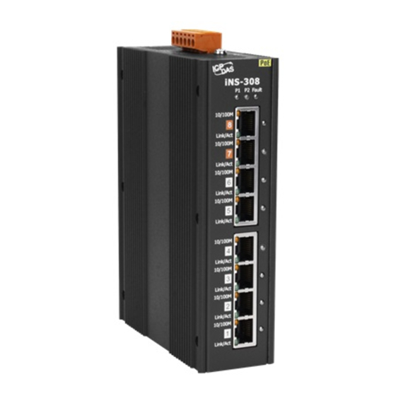
Page 8: Hardware Information
User Manual 2. Hardware Information 2.1 Appearance Front View ToP View Power LED indicator LED indicator Color status Description Power is being supplied to power input PWR1. Green Power is not being supplied to power input PWR1 Power is being supplied to power input PWR2. - Page 9 Once the power is supplied, thecorresponding LED indicator lights up. Each PoE port can provide up to 30 W of power. If the iNS-308 is utilized under high load (total PoE loadexceeds 60 W), it is recommended to configure dual power supplies.
-
Page 10: Specification
User Manual 2.2 Specification Model iNS-308 PoE Technology PoE Compliance 100% IEEE 802.3at compliant PoE Power Up to 30 watts per port PoE Pin Assignments V+ (pin 1, 2), V-(pin 3, 6) , alternative A PoE Voltage +53 VDC... -
Page 11: Ethernet And Poe Pin Out
User Manual 2.3 Ethernet and PoE Pin Out The pinout follows the Alternative A of IEEE 802.3af/802.3at standards. Please see the details in the following table Pin No Ethernet 2.4 Dimensions (unit = mm) Copyright © 2022 ICP DAS CO., Ltd. All Rights Reserved. -
Page 12: Getting Started
Contact the System Administrator for instructions of how to do this. Step 2: Apply power (+24 ~ +57 V ) to the iNS-308. Copyright © 2022 ICP DAS CO., Ltd. All Rights Reserved. - 12 -... -
Page 13: Configuring The Network Settings
User Manual 3.2 Configuring the Network Settings Step 1: Get the eSearch Utility The eSearch Utility can be obtained from the ICP DAS Web site at: https://www.icpdas.com/en/product/guide+Software+Utility_Driver+eSearch__Utility Step 2: Install the eSearch Utility Follow the instructions in the eSearch setup wizard to complete the installation. - Page 14 User Manual Step 4: Double-click your module name to open the configuration dialog box Factory Default Settings 192.168.255.1 Gateway 192.168.0.1 Mask 255.255.0.0 Step 5: Assign new network settings and then click the “OK” button Enter the relevant values for the IP Address, Subnet Mask, Gateway, etc., and then click the “OK”...
- Page 15 User Manual Step 7: Click the “Web” button to connect to the web interface (Or entering the iNS-300's IP address into a web browser) Step 8: Change password upon first login The default password for logging in to the iNS-300 web page is Admin. You will be prompted to change your password upon first login or when the password is the same as the default.
-
Page 16: Web Configuration
User Manual 4. Web Configuration The iNS-308 has a built-in Web Server, which provides an intuitive web interface, allowing users to login to the module for monitoring the physical status of an Ethernet or PoE port, configuring and managing module settings through a browser. - Page 17 The current of connected PoE devices (unit: mA) Watt(W) The power consumption of connected PoE devices (unit: W) TEMP (℃) Display iNS-308 PoE Port(inside) temperature Display PoE device Class level for power N/D – No Device Class 0 – Range 0~15.4W Class 1 –...
-
Page 18: Schedule
User Manual 4.2 Schedule On the Schedule page, you can manage the power schedule for PoE powered device(s) in a week. The first section provides PoE Port select、schedule Enable/Disable and reset delay configure interface. Whan, Power On Schedule set to “Enable” and Power schedule setup is complete, must click “Update Settings”... -
Page 19: Network
User Manual 4.3 Network The Network page contains the IP Address Configuration section allowing you to verify network settings, General Settings, Restore Factory Defaults and Firmware Update sections. Each of which will be described in more detail below. The IP Address Configuration section displays the network parameters of the module allowing you to modify these settings. - Page 20 User Manual DHCP Configuration If a DHCP server is connected to you network, a network address can be dynamically assigned by enabling DHCP client mode. Step 1: Select “DHCP” from the Address Type drop-down menu. Step 2: Click the “Update Settings” button to complete the configuration.
- Page 21 Set the automatic logout time. The user will be log out after the Web Auto-logout predetermined period of inactivity on web interface has elapsed Assign the alias name. Assigning a unique alias to each iNS-308 helps Alias Name to identify multiple modules on the same network.
- Page 22 User Manual You can restore the iNS-300 series module to factory default settings or reboot it in the Other Operations section. Restoring Factory Default Settings Step 1: Click the “Restore Defaults” button. Step 2: Click “OK” on the pop-up dialog box.
- Page 23 User Manual Rebooting the Module Step 1: Click the “Reboot” button in the right field of Force Reboot. Step 2: After the module restarts, reload the web interface and log into the module again. Copyright © 2022 ICP DAS CO., Ltd. All Rights Reserved.
- Page 24 User Manual Updating Firmware Generally, you have to manually put the operating mode switch(1) in INIT position and reboot the iNS-300 series module to update the firmware. But when the iNS-300 series module is deployed on the ceiling or in areas that are isolated and hard to reach, you can update firmware by clicking the “Reboot”...
-
Page 25: Snmp
Note. Modify the SNMP Enable status please reboot the iNS-308 to activate the Modification iNS-308 provide PoE Power Enable & Link status trap function, then status Modify will sead information to your Trap IP, more information, please refer to the iNS-300 SNMP manual Copyright ©... -
Page 26: Filter
User Manual 4.5 Filter The Filter page is used to query or edit the IP Filter list (Allow IP List) for the iNS-300 series module. The IP filter list restricts the access of incoming packets based on the IP address. If one or more IP addresses are saved into the Allow IP List, only clients that have an IP address within the filter list can access the iNS-300 series module. -
Page 27: Changing Password
User Manual Changing Password You can change password on the Password page. Step 1: Enter your current password in the “Current password” field. Step 2: Enter your new password in the “New password” field. (1 ~ 12 alphanumeric characters are allowed) Step 3: Enter your new password in the “Confirm new password”... -
Page 28: Logout
User Manual 4.7 Logout Click “Logout” on the navigation bar to log out of your account. It redirects you to the login page Copyright © 2022 ICP DAS CO., Ltd. All Rights Reserved. - 28 -... -
Page 29: Poe Function Configure
You can configure a weekly schedule for each PoE port individually to reboot the attached devices. The iNS-308 will check the schedule every hour on the hour. If the checkbox for reset function is selected, the power on a POE port will be turned off and turned on again for specified time interval Step1: Select the PoE port number, setting Enable/Disable and the period between turning off the PoE power and turning it back on again. - Page 30 User Manual table provide bulk selection functionality, Click”Toggle On/Off” or “Toggle Reset” will select all time at a day Click”0” to “23”will select all day at a time, Copyright © 2022 ICP DAS CO., Ltd. All Rights Reserved. - 30 -...
-
Page 31: Poe Power Limit
User Manual 5.3 PoE Power Limit In addition to supporting the IEEE802.3af/at Class limit, iNS-308 also provides the PoE Output Limit function for selection. When the Class Defined Power Limit is checked (default) on the Home page of the web page, the power supply and overload protection will be in accordance with IEEE802.3af The Class classification... -
Page 32: Advanced Ethernet Configure
6. Advanced Ethernet configure 6.1 Loop Detect iNS-308 has built-in network loop detection. When a loop occurs in the network configuration, iNS- 308 will flash a light to remind the loop and perform packet control on the network port where the loop has occurred, which can reduce the loop caused to a certain extent. -
Page 33: Modbus Information
User Manual 7. Modbus Information The iNS-308 allow you to remotely control Power & configure terminals via an Ethernet connection and uses a master-slave communication technique in which only one device (the master) can initiate a transaction (called queries), while other devices (slaves) respond by either supplying the requested data to the master, or by taking the action requested in the query. -
Page 34: Modbus Message Structure
User Manual 7.2 Modbus Message Structure Modbus devices communicate using a master-slave (client-server) technique in which only one device (the master/client) can initiate transactions (called queries). The other devices (slaves/servers) respond by either supplying the requested data to the master, or by taking the action requested in the query. - Page 35 User Manual Net ID (Station Number) The first byte in the frame structure of a Modbus RTU query is the address of the receiver. A valid address is in the range from 0 to 247. Address 0 is used for general broadcast purposes, while addresses 1 to 247 are assigned to individual Modbus devices.
-
Page 36: 0X01) Read The Status Of The Coils (Read Do Readback Vaslues)
User Manual 7.2.1 01(0x01) Read the Status of the Coils (Read DO Readback vaslues) This function code is used to read either the current status of the coils or the current Digital Output readback value from the iNS-308 [Request] Byte Description... -
Page 37: 0X02) Read The Status Of The Input (Read Di Values)
User Manual 7.2.2 02(0x02) Read the Status of the Input (Read DI values) This function code is used to read the current Digital Input value from the iNS-308 [Request] Byte Description Size Value Net ID (Station Number) 1 Byte... -
Page 38: 0X03) Read The Holding Registers (Read Ao Readback Values )
This function code is used to readback either the current values in the holding registers or the Analog Output value from the iNS-308. These registers are also used to store the preset valuesfor the Digital Counter, the host watchdog timer, the module name and the TCP timeout, etc. -
Page 39: 0X04) Read The Input Registers (Read Ai Values)
This function code is used to read either the input registers or the current analog input value from the iNS-308. These registers are also used to store the current value for the digital counter, the number of DI channels and the number of DO channels, etc. -
Page 40: 0X05) Force A Single Coil (Write Do Value)
User Manual 7.2.5 05(0x05) Force a Single Coil (Write DO value) This function code is used to set the status of a single coil or a single Digital Output value for the iNS-308. [Request] Byte Description Size Value Net ID (Station Number) -
Page 41: 0X06) Set A Single Register (Write Ao Value)
User Manual 7.2.6 06(0x06) Set a Single Register (Write AO value) This function code is used to set a specific holding register to store the configuration valuesfor the iNS-308. [Request] Byte Description Size Value Net ID (Station Number) 1 Byte... -
Page 42: 0X0F) Force Multiple Coils (Write Do Values)
User Manual 7.2.7 15(0x0F) Force Multiple Coils (Write DO values) This function code is used to set the status of multiple coils or to write multiple Digital Output values for the iNS-308 [Request] Byte Description Size Value Net ID (Station Number) -
Page 43: 0X10) Set Multiple Registers (Write Ao Values)
User Manual 7.2.8 16(0x10) Set Multiple Registers (Write AO values) This function code is used to set multiple holding registers that are used to store the configuration valuesfor the iNS-308. [Request] Byte Description Size Value Net ID (Station Number) -
Page 44: Modbus Register Table
User Manual 7.3 Modbus Register Table 0xxxx: DO address (Base 0) Address Description Range Access Type 00000~00007 PoE Enable 0=OFF, 1=ON PoE CDPL enable 0=Disable 00032 Auto Class Define Power Limit 1=Enable 0=Disable 00040 Ethernet Jumbo Frame 1=Enable... - Page 45 User Manual 4xxxx: AO address (Base 0) Address Description Range Access Type 1 => 4W 2 => 7W 40000~40007 PoE Host Power output Limit 3 => 15.5W 4 => 30W 0 => auto negotiation 1 => 100M Full...
-
Page 46: Revision History
User Manual Revision History Revision Date Description 1.0.0 Dec.2022 Copyright © 2022 ICP DAS CO., Ltd. All Rights Reserved. - 46 -...
Need help?
Do you have a question about the iNS-308 and is the answer not in the manual?
Questions and answers