Table of Contents
Advertisement
Quick Links
®
9640A
RF Reference Source
Applicable only to older 9640A & 9640A-LPN units with firmware up to lss 2.X.
Instruction Manual
August 2006 Rev. 4, 7/10
© 2006-2010 Fluke Corporation, All rights reserved. Specifications are subject to change without notice.
All product names are trademarks of their respective companies.
Advertisement
Table of Contents

Related Manuals for Fluke 9640A Series


Summary of Contents for Fluke 9640A Series
- Page 1 Applicable only to older 9640A & 9640A-LPN units with firmware up to lss 2.X. Instruction Manual August 2006 Rev. 4, 7/10 © 2006-2010 Fluke Corporation, All rights reserved. Specifications are subject to change without notice. All product names are trademarks of their respective companies.
- Page 2 Fluke authorized resellers shall extend this warranty on new and unused products to end-user customers only but have no authority to extend a greater or different warranty on behalf of Fluke. Warranty support is available only if product is purchased through a Fluke authorized sales outlet or Buyer has paid the applicable international price.
- Page 3 Les distributeurs agréés par Fluke appliqueront cette garantie à des produits vendus neufs et qui n’ont pas servi, mais ne sont pas autorisés à offrir une garantie plus étendue ou différente au nom de Fluke. Le support de garantie est offert uniquement si le produit a été acquis par l'intermédiaire d'un point de vente agréé...
- Page 4 Produkt innerhalb der Garantiefrist einem von Fluke autorisierten Servicezentrum zur Reparatur übergeben wird. Um die Garantieleistung in Anspruch zu nehmen, wenden Sie sich bitte an das nächstgelegene von Fluke autorisierte Servicezentrum, um Rücknahmeinformationen zu erhalten, und senden Sie dann das Produkt mit einer Beschreibung des Problems und unter Vorauszahlung von Fracht- und Versicherungskosten (FOB- Bestimmungsort) an das nächstgelegene von Fluke autorisierte Servicezentrum.
- Page 5 Fluke. El soporte técnico en garantía está disponible sólo si el producto se compró a través de un centro de distribución autorizado por Fluke o si el comprador pagó el precio internacional correspondiente.
- Page 6 認定販売店で購入されるか、または購入者が適当な国際価格を支払った場合に保証のサポートが受けられま す。 ある国で購入された製品が修理のため他の国へ送られた場合、Fluke は購入者に、修理パーツ/交換 パーツの輸入費用を請求する権利を保有します。 Fluke の保証義務は、Fluke の見解に従って、保証期間内に Fluke 認定サービス・センターへ返送された欠陥 製品に対する購入価格の払い戻し、無料の修理、または交換に限られます。 保証サービスを受けるには、最寄りの Fluke 認定サービス・センターへご連絡いただき、返送の許可情報を 入手してください。 その後、問題個所の説明と共に製品を、送料および保険料前払い (FOB 目的地) で、最 寄りの Fluke 認定サービス・センターへご返送ください。 Fluke は輸送中の損傷には責任を負いません。 保 証による修理の後、製品は購入者に送料前払い(FOB 到着地)で返送されます。 当故障が、使用上の誤り、 汚染、変更、事故、または操作や取り扱い上の異常な状況によって生じたと Fluke が判断した場合には、 Fluke は修理費の見積りを提出し、承認を受けた後に修理を開始します。 修理の後、製品は、輸送費前払 いで購入者に返送され、修理費および返送料 (FOB 発送地) の請求書が購入者に送られます。 本保証は購入者の唯一の救済手段であり、ある特定の目的に対する商品性または適合性に関する黙示の保証 をすべて含むがそれのみに限定されない、明白なまたは黙示の他のすべての保証の代りになるものです。...
- Page 7 有限担保及责任范围 Fluke 公司保证其每一个 Fluke 的产品在正常使用及维护情形下,其用料和做工都是毫无瑕疵的。保证期限是 一年并从产品寄运日起开始计算。零件、产品修理及服务的保证期是 90 天。本保证只提供给从 Fluke 授权经 销商处购买的原购买者或最终用户, 且不包括保险丝、电池以及因误用、改变、疏忽、或非正常情况下的使 用或搬运而损坏(根据 Fluke 的意见而定)的产品。Fluke 保证在 90 天之内,软件会根据其功能指标运行, 同时软件已经正确地被记录在没有损坏的媒介上。Fluke 不能保证其软件没有错误或者在运行时不会中断。 Fluke 仅授权经销商将本保证提供给购买新的、未曾使用过的产品的最终用户。经销商无权以 Fluke 的名义来 给予其它任何担保。保修服务仅限于从 Fluke 授权销售处所购买的产品,或购买者已付出适当的 Fluke 国际价 格。在某一国家购买而需要在另一国家维修的产品,Fluke 保留向购买者征收维修/更换零件进口费用的权 利。 Fluke 的保证是有限的,在保用期间退回 Fluke 授权服务中心的损坏产品,Fluke 有权决定采用退款、免费维 修或把产品更换的方式处理。 欲取得保证服务,请和您附近的 Fluke 服务中心联系,或把产品寄到最靠近您的 Fluke 服务中心(请说明故障...
-
Page 9: Table Of Contents
Frequency Sweep Specifications ..............1-18 GPIB Command Emulation Mode Specifications......... 1-18 Preparing the Instrument for Operation ..........2-1 Introduction......................2-3 Contacting Fluke....................2-3 Unpacking and Inspection.................. 2-3 Storing and Shipping the Instrument ..............2-4 Power Considerations ..................2-5 Replacing the Power Cord................2-5 Replacing the Line-Power Fuses .............. - Page 10 9640A Instruction Manual Controls, Indicators, and Connectors..............3-3 Head I/O Connectors ..................3-4 STBY/OPER (Standby/Operate) Keys............3-4 Output Function Keys..................3-4 Output Signal Keys ................... 3-4 UNITS Key ....................3-5 SETUP Key....................3-5 Display......................3-6 Data Fields ....................3-7 Soft Labels ....................3-7 Status Bar ....................
- Page 11 (continued) Contents Saving an Instrument Setup ..............3-35 Saving Settings for an Output Function ............ 3-36 Recalling Settings..................3-36 Creating an RF Output Signal ............... 3-36 Creating a Leveled Sine Output Signal ............3-37 Setting Leveled Sine Preferences.............. 3-37 Setting Externally Leveled Sine Preferences ..........3-38 Setting Reference Switching Preferences ..........
- Page 12 9640A Instruction Manual Command Tree ....................4B-11 Moving down the Command Tree..............4B-11 Parameters......................4B-12 Numeric Data....................4B-12 Boolean Data ....................4B-12 Other Data Types................... 4B-12 Initialization and Resetting ................4B-13 Reset Strategy....................4B-13 Bus Initialization ..................4B-13 Message Exchange Initialization............... 4B-13 Device Initialization ..................
- Page 13 (continued) Contents FM Subsystem ....................4C-11 PM Subsystem ....................4C-12 SWEep Subsystem..................4C-13 Trigger Subsystem..................4C-14 REFerence Subsystem ................... 4C-15 UNIT Subsystem ................... 4C-16 UNIT Subsystem (cont.)................4C-17 ROSCillator Subsystem................. 4C-18 SYSTem Subsystem ..................4C-18 STATus Subsystem ..................4C-19 CALibration Subsystem ................4C-19 Common Commands ..................
- Page 14 User Interface ....................6-5 Frequency Synthesis..................6-5 Amplitude Control..................6-5 Frequency Modulation................... 6-6 Amplitude Modulation .................. 6-6 Instrument Control..................6-6 Power Supplies ....................6-7 Maintenance..................7-1 Introduction......................7-3 Contacting Fluke....................7-3 General Maintenance ..................7-3 Replacing Fuses..................... 7-3 Cleaning the Air Filter................... 7-3...
- Page 15 (continued) Contents Disassembly and Reassembly ................7-4 Before You Start.................... 7-5 Removing External Hardware Components ..........7-5 Handles...................... 7-5 Top and Bottom Covers ................7-6 Bottom Feet....................7-6 Shields....................... 7-6 Air Filter ......................7-6 Removing Major Assemblies ................ 7-8 A2 RF Output PCA ................... 7-8 1P 2W Coaxial Relay ................
- Page 16 9640A Instruction Manual viii...
- Page 17 List of Tables Table Title Page 2-1. List of Contents ...................... 2-4 2-2. Dimensions for a Substitute Cushioned Shipping Container ......... 2-4 2-3. Power Cord for Various Regions ................2-5 2-4. Power Input Fuse....................2-6 2-5. Voltage Limits for the 115 and 230 Voltage Switch Settings ........ 2-7 3-1.
- Page 18 9640A Instruction Manual 5-2. Frequency Accuracy Test..................5-8 5-3. Harmonics Test ...................... 5-11 5-4. Spurious Content Test .................... 5-11 5-5. Phase Noise Test (9640A only)................5-13 5-6. Phase Noise Test (9640A-LPN only)..............5-14 5-7. AM Rate Test ......................5-15 5-8. AM Depth Test.......................
- Page 19 List of Figures Figure Title Page 1-1. 9640A RF Reference Source ................1-7 2-1. Accessing the Fuse and Changing Line Voltage ..........2-7 3-1. Front Panel Controls, Indicators, and Connectors..........3-3 3-2. Status Bar ......................3-8 3-3. Control Screens for the RF Output Signal............3-12 3-4.
- Page 20 9640A Instruction Manual Points........................ 5-36 Equipment Connections- Level Accuracy Tests (75 Ω), High Frequency 5-10. Points......................... 5-38 Equipment Connections- Level Accuracy Tests (75 Ω), Low Level Points ..5-40 5-11. Equipment Connections - Attenuation Accuracy Test (75 Ω)......5-46 5-12. Equipment Connections - VSWR Test (75 Ω) ............
- Page 21 Chapter 1 Introduction and Specifications Title Page About the Manual ....................1-3 Safety Information ....................1-3 General Safety Summary................. 1-3 Symbols ......................1-6 Product Description ..................... 1-7 Options and Accessories ..................1-8 Specifications....................... 1-9 General Specifications..................1-9 Frequency Reference Input/Output Specifications.......... 1-10 Leveled Sine Specifications................
- Page 22 9640A Instruction Manual...
-
Page 23: Introduction And Specifications
Introduction and Specifications About the Manual About the Manual This is the Instruction Manual for the 9640A RF Reference Source (hereafter referred to as the Instrument) and its options and accessories. It contains all of the information a user will need to operate and maintain the Instrument effectively. The manual is divided into the following chapters: Chapter 1 Introduction and Specifications... - Page 24 9640A Instruction Manual Safety Information XW Warning To avoid electric shock, personal injury, fire, or death, read the following warnings before using the Instrument: • Use the Instrument only as specified in this manual, or the protection provided by the instrument might be impaired.
- Page 25 • The front panel connectors on the Instrument are suited only for use with Fluke 9640A-xx Leveling Heads. No other connection is permitted. • The Leveling Heads are fitted with close tolerance metrology grade N-connectors compliant with MIL-C-39012 and MMC Standards for Precision N-connectors.
-
Page 26: Symbols
IEC 61010 Overvoltage (installation or measurement) Category. < Potentially hazardous voltage. Recycle. Static awareness. Static discharge can Do not dispose of this product as unsorted damage part(s). municipal waste. Go to Fluke’s website for recycling information. Power ON / OFF... -
Page 27: Product Description
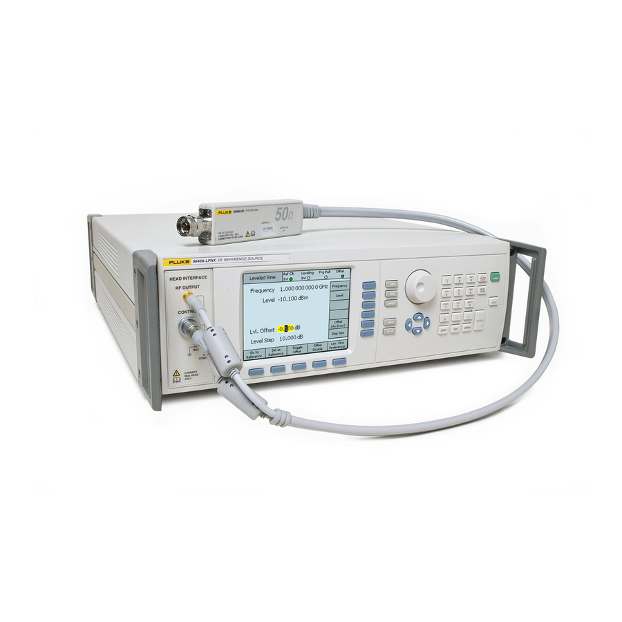
Introduction and Specifications Product Description Product Description The Instrument is an RF Reference Source designed to create the signals needed for precision RF and microwave applications. See Figure 1-1. Signal delivery via interchangeable Leveling Heads ensures a unique combination of level accuracy, dynamic range, and frequency coverage in both 50 Ohm and 75 Ohm systems. -
Page 28: Options And Accessories
9640A Instruction Manual Options and Accessories Table 1-1 provides a list of the products, options and accessories available. When ordering an option or accessory after the original purchase, include a reference to the Instrument as well as the description from the following table. Table 1-1. -
Page 29: Specifications
Introduction and Specifications Specifications Specifications General Specifications Performance All specifications apply to a 1 year calibration interval at an ambient temperature of Tcal ±5 °C. Nominal factory Tcal calibration temperature 23 °C. Standard Interfaces IEEE488.2 (GPIB) Warmup Time 60 minutes Temperature 0 °C to 50 °C Operating:... -
Page 30: Frequency Reference Input/Output Specifications
9640A Instruction Manual Frequency Reference Input/Output Specifications Frequency Reference Input Rear panel Reference Frequency Input BNC connector Frequency 9640A: 1 MHz to 20 MHz in 1 MHz steps ±30 ppm 9640A-LPN: 1 MHz to 20 MHz in 1 MHz steps ±1 ppm 1 V pk nominal into 50 Ω, ±5 V pk max. - Page 31 Introduction and Specifications Specifications 50 Ω output 75 Ω output Attenuation Attenuation Relative to +16 dBm output Relative to +10 dBm output 100 kHz to 128 MHz 0 - 33 dB ±0.035 dB 0 - 33 dB ±0.035 dB 33 - 64 dB ±0.04 dB 33 - 64 dB ±0.05 dB...
- Page 32 9640A Instruction Manual 75 Ω Output Absolute Amplitude Accuracy Amplitude 10 Hz >20 kHz 100 kHz 10 MHz >125 MHz >300 MHz >1.4 GHz >3 GHz 20 kHz <100 kHz <10 MHz 125 MHz 300 MHz 1.4 GHz 3 GHz 4 GHz >+14 to +18 ±0.06 dB ±0.06 dB...
- Page 33 Introduction and Specifications Specifications SSB Phase Noise At maximum output level, Internal Freq Ref, (dBc/Hz) Frequency Offset from Carrier 10Hz 100Hz 1kHz 10kHz 100kHz 1MHz 10MHz Spec (Typ) Spec (Typ) Spec (Typ) Spec (Typ) Spec (Typ) Spec (Typ) Spec (Typ) 9640A 1GHz Not Spec’d...
-
Page 34: Modulation Specifications
9640A Instruction Manual External Leveling Input Rear panel Modulation, Leveling and Frequency Pull BNC connector, 10 kΩ nominal input impedance. For external power meter leveling User adjustable full scale voltage, 1 V to 5 V, positive polarity. Maximum Input ±5 V External Frequency Control Input Rear panel Modulation, Leveling and Frequency Pull BNC connector, 10 kΩ... - Page 35 Introduction and Specifications Specifications AM External Input Rear panel Modulation, Leveling and Frequency Pull BNC connector, 10 kΩ nominal input impedance. Bandwidth (-3 dB) DC coupled: DC to 220 kHz typical. AC coupled: 10 Hz to 220 kHz typical. Depth Sensitivity User adjustable, 0.5 %/V to 400 %/V Input Level ±2 V pk maximum operating, ±5 V pk absolute maximum...
- Page 36 9640A Instruction Manual Frequency and Phase Modulation Waveform FM: Sinusoidal, or External signal. PM: Sinusoidal only. Carrier Frequency (Fc) 9 MHz to 4 GHz Carrier Frequency Accuracy Internal Frequency Reference: 0.04 ppm + 240 mHz External Frequency Reference: Ext Freq Ref Accuracy + 240 mHz Rate (Fr) 1 Hz to 300 kHz Rate Resolution...
- Page 37 Introduction and Specifications Specifications FM External Input Rear panel Modulation Leveling and Frequency Pull BNC connector, 10 kΩ nominal input impedance. Bandwidth (-3 dB) DC coupled: DC to 300 kHz typical. AC coupled: 10 Hz to 300 kHz typical. Deviation Sensitivity User adjustable, 500 Hz/V to 19 MHz/V, carrier frequency dependent.
-
Page 38: Frequency Sweep Specifications
9640A Instruction Manual Frequency Sweep Specifications Sweep Frequency Range 10 Hz to 4 GHz Sweeps are generated as a sequence of discrete synthesized frequencies. Sweep Modes Stop - Start and Center - Span Linear or Logarithmic Repetitive, Single Shot, triggered and Manual Sweep Squelch or Non Squelch at frequency transitions Frequency Resolution <100 MHz: 0.1 Hz, >100 MHz: 11 digits... -
Page 39: Preparing The Instrument For Operation
Chapter 2 Preparing the Instrument for Operation Title Page Introduction......................2-3 Contacting Fluke....................2-3 Unpacking and Inspection ................... 2-3 Storing and Shipping the Instrument ..............2-4 Power Considerations ..................2-5 Replacing the Power Cord................2-5 Replacing the Line-Power Fuses ..............2-6 Selecting Line Voltage .................. - Page 40 9640A Instruction Manual...
-
Page 41: Introduction
Instrument. The Instrument is an unbalanced load and weighs up to 18 kg (40 pounds). Fluke has taken great care to ensure that the Instrument arrives in perfect condition. When the Instrument arrives, carefully unpack and inspect for external damage to the case, front panel, and rear panel. -
Page 42: Storing And Shipping The Instrument
9640A Instruction Manual Table 2-1. List of Contents Description Quantity 9640A RF Reference Source 9640A-50 Leveling Head 9640A-75 Leveling Head Optional Carrying/Storage Case (for two Leveling Heads and the 9600CONN RF Interconnect Kit ) 9640A Getting Started Manual, English CD ROM – Manual Set Line Cord Certificate of Calibration Storing and Shipping the Instrument... -
Page 43: Power Considerations
Match this LC number to one of the plugs in the drawing, and verify that the plug on your power cable mates correctly with the local power outlets. If the plug is incorrect, identify the correct LC number, and order the correct power cable from Fluke using the part number from Table 2-3. -
Page 44: Replacing The Line-Power Fuses
5. Reinstall the fuse compartment by pushing it back into place until the tab locks. Table 2-4. Line-Power Fuse Fuse Rating Manufacturer Line Power Fuse Action Fluke Part No. IEC 127 and Type No. 2650727 115 V AC 10 A @ 250 V... - Page 45 SH1 AH1 T6 L4 SR1 OUTPUT AUX PRO TECTIVE RL1 PP0 DC1 DT0 C0 E2 1V PK INT O EAR TH (GROUND) FLUKE CORPORA TION www .f l uk e .com TTL INT O 1k NOM MADE IN UK Power...
-
Page 46: Power-On Sequence
9640A Instruction Manual Power-On Sequence Note The power-on sequence may be run with or without a Leveling Head connected to the Instrument. After connecting the Instrument to line power, use the power switch on the rear panel to power-on the Instrument. See Figure 2-1. The Instrument displays an initialization screen for about 4 seconds during the power-on sequence and then runs a power-on self test. -
Page 47: Power-On State
Preparing the Instrument for Operation Power-On Sequence Power-On State After completing the power-on self test, the Instrument enters the Standby state (output off) as indicated by the illuminated key on the far-right of the front panel. At first power-on, the Instrument displays the following screen. Press to obtain an RF output. -
Page 48: Leveling Head Connections
9640A Instruction Manual Leveling Head Connections W Warning To prevent hazardous RF transmissions and equipment damage, read and follow the instructions in Chapter 3 before connecting a Leveling Head to the Instrument or to a UUT. Instructions for connecting a Leveling Head to the Instrument and to a unit under test (UUT) are given in Chapter 3, Local Operation. -
Page 49: Local Operation
Chapter 3 Local Operation Title Page Introduction......................3-3 Controls, Indicators, and Connectors..............3-3 Head I/O Connectors ..................3-4 STBY/OPER (Standby/Operate) Keys............3-4 Output Function Keys..................3-4 Output Signal Keys ..................3-4 UNITS Key ....................3-5 SETUP Key....................3-5 Display......................3-6 Data Fields .................... - Page 50 9640A Instruction Manual Rear-Panel Controls and Connectors ..............3-21 Power Block and Switch ................. 3-21 IEEE 488 Connector..................3-21 Reference Frequency Output Connector ............3-22 Reference Frequency Input Connector ............3-22 Modulation, Leveling and Frequency Pull Input Connector ......3-23 Trigger I/O Connector ..................
-
Page 51: Introduction
Local Operation Introduction Introduction This chapter provides a comprehensive introduction of all of the external features and functions on the Instrument, followed by instructions for operating the Instrument. The introduction identifies each of the front- and rear-panel controls, connectors, and indicators (including screens), and describes the intended use for each. -
Page 52: Head I/O Connectors
Caution The 9640A front-panel connector interface is suited only for use with Fluke 9640A-xx Leveling Heads. To avoid damage to the Instrument no other connection is permitted. The function of a Leveling Head is to deliver the Instrument output to the input of another instrument (UUT) while maintaining the integrity of the signal. -
Page 53: Units Key
Local Operation Controls, Indicators, and Connectors UNITS Key Use the key to display a list of the measurement units available for use with the selected data field. The list is context sensitive and appears on the vertical soft labels. Pressing a blue soft key adjacent to one of the displayed measurement units selects and applies that unit to the value in the selected field. -
Page 54: Display
9640A Instruction Manual Pressing the Calibration soft key brings up a Calibration screen which allows users to correctly associate the Base Unit and Leveling Heads that have been calibrated together. The Calibration screen shows the serial numbers of the 50 Ω and 75 Ω Leveling Heads with which the Base Unit is calibrated. - Page 55 Local Operation Controls, Indicators, and Connectors Data Fields Data fields contain numeric values that effectively describe the present output parameters of the Instrument. Following power-on, these fields all contain default values. To change or edit these values the user must do the following: 1.
-
Page 56: Status Bar
9640A Instruction Manual Status Bar The status bar consists of two regions across the top of the display (see Figure 3-2). There are no keys associated with the status bar as its only function is to provide information. Typically, the left-most label defines the RF Output signal: sine, modulated, or swept. It also indicates a GPIB command emulation mode. -
Page 57: Field Editor
Local Operation Controls, Indicators, and Connectors Field Editor There are two control sets for incrementally editing field data. They are the cursor keys and the spin wheel. Cursor Keys The cursor keys are a group of four keys marked with right, left, up and down arrows: (, , , ). -
Page 58: Keypad
9640A Instruction Manual Keypad The alphanumeric keypad supports direct keypad edit of a numeric field. Alpha entry is also supported, but only to allow the naming of user Saved Set-ups. ALPHA ALPHA ALPHA LOCK LOCK NEXT NEXT CHAR CHAR PQRS PQRS WXYZ WXYZ... -
Page 59: Alpha Key
Local Operation Controls, Indicators, and Connectors ALPHA Key The key controls access to the numeric (default level 1) and alpha (level 2) characters. The key operates in a toggle mode. When the light is off, the numeric characters are accessible. Pressing to light the key enables access to the alpha characters. -
Page 60: Exp Key (Exponent)
9640A Instruction Manual EXP Key (Exponent) The key allows the user to enter numeric data using an exponent. While entering a number, pressing ends the numeric sequence by inserting a capital letter E to indicate that the following number is an exponent. ead37f.eps Exponent Key ENTER Key... -
Page 61: Editing Settings - The Vertical Soft Keys
Local Operation Screen Controls and Indicators Pressing sets the Instrument to standby and brings up the Leveled-Sine screen, establishing the sine wave as the selected RF output signal. The same is true of the and keys. As each key is pressed, the instrument enters standby and brings up the corresponding modulation or sweep screens. - Page 62 9640A Instruction Manual ead15f.bmp Leveled Sine Step Edit If, when in the Cursor edit mode, the soft label includes a (Step edit) marking, pressing the soft key for the focus field changes the edit mode to Step edit. Notice that Step edit is not available for inappropriate fields.
- Page 63 Local Operation Screen Controls and Indicators Keypad Edit At any time, a new value may be entered directly in a numeric focus field via the Keypad. The first press of a numeric key will open an edit box in place of the current field and present scientific multiplier options on the vertical soft keys.
-
Page 64: Expanded Settings - The Horizontal Soft Keys
9640A Instruction Manual Note The Instrument supports multiple unit scales for display and editing. Each scale has finite resolution, and the finite steps of each scale will not necessarily align. It is therefore possible that conversion of a setting to a different unit followed by conversion back to the original unit could cause a one-step shift in the setting. -
Page 65: Offset Soft Key
Local Operation Screen Controls and Indicators Offset Soft Key The Offset key allows the operator to adjust the Instrument output via an offset from the main setting. The soft label tracks the focus field, allowing control of either Frequency Offset or Level Offset. For example, assuming Level to be the current focus field, pressing the Offset soft key will add and select the Level Offset field as the new focus field. -
Page 66: Toggle Offset Soft Key
9640A Instruction Manual Toggle Offset Soft Key Note that while the Offset field is present, a Toggle Offset soft key is also present. In the following Leveled-Sine – Toggle Offset screen, the Toggle Offset soft key may be pressed at any time to remove the offset from the output. The initial (Offset = 0) value is restored and the Offset indicator on the Status Bar turns off. -
Page 67: Reference Soft Keys
Local Operation Screen Controls and Indicators Reference Soft Keys For the Leveled Sine function, the Instrument user interface also supports a Reference Frequency, a Reference Level or a Reference Point (Frequency and Level). References may be an output setting that the user might need to return to frequently during a calibration application, perhaps to check or adjust for stability. -
Page 68: Reference Off Soft Key
9640A Instruction Manual Reference Off Soft Key The Reference Off soft key returns the Instrument to the Leveled-Sine screen and its output settings. The message Switch from Reference – Confirm with Operate may appear if switching confirmation has been selected as a Reference Preference. Frequency and Level Track Main Soft Keys The Set as Reference soft key always transfers the current Level and Frequency settings into the reference settings. -
Page 69: Rear-Panel Controls And Connectors
SH1 AH1 T6 L4 SR1 OUTPUT AUX PR O TECTIVE RL1 PP0 DC1 DT0 C0 E2 1V PK INT O EARTH (GR O UND) FLUKE CORPORA T ION www .f l uk e .com TTL INT O 1k NOM MADE IN UK ... -
Page 70: Reference Frequency Output Connector
9640A Instruction Manual Reference Frequency Output Connector The Reference Frequency Output Connector is a rear-panel BNC connection that provides access to an internally generated reference frequency. See Table 3-1 for the output specifications. Table 3-1. Reference Frequency Output Specifications Parameter Specification Comments Connector Type... -
Page 71: Modulation, Leveling And Frequency Pull Input Connector
Local Operation Rear-Panel Controls and Connectors Modulation, Leveling and Frequency Pull Input Connector The Modulation, Leveling and Frequency Pull Input Connector is a BNC connection for applying a multifunction external control signal to the Instrument. Depending upon the operating settings of the Instrument, the signal may be tailored for modulation control, frequency control, or leveling control. -
Page 72: Trigger I/O Connector
9640A Instruction Manual Table 3-4. External Modulation Input Specifications (AM) Parameter Specification Comments Connector Type Input Referenced to RF Common (floating) Frequency Range DC – 220 kHz -3 dB Bandwidth, DC coupled 10 Hz – 220 kHz -3 dB Bandwidth, AC coupled 100 kHz max. -
Page 73: Operating The Instrument
Local Operation Operating the Instrument Table 3-7. Sweep Trigger Input Specifications Parameter Specification Comments Connector Type Input Referenced to RF Common (floating) Trigger Amplitude TTL , +5 V pk max Selectable as rising or falling edge Input Impedance 10 kΩ Nominal ≤1 ms Typical Time alignment... -
Page 74: Setting Global Preferences
9640A Instruction Manual Setting Global Preferences The Instrument setup screen describes the basic instrument configuration and gives the user access to all user preference setup screens. Use the following procedure to set the global preferences: 1. Press ; the Instrument Setup screen appears. ead05f.bmp Instrument setup 2. -
Page 75: Local Or Remote Operation
Local Operation Operating the Instrument Local or Remote Operation Manual user interaction at the front panel of the Instrument is considered local operation. Remote operation requires the use of remote data supplied to the Instrument by way of an IEEE 488 connection at the rear panel. Chapter 4 provides all of the information required to remotely operate the Instrument. -
Page 76: Selecting And Changing The Address Of A Command Emulation
9640A Instruction Manual Selecting and Changing the Address of a Command Emulation Use the following procedure to select or deselect a GPIB personality or to change the GPIB Address of the Instrument or of an emulation personality: 1. From the Setup screen, press the GPIB Preferences soft key to display the GPIB Personality screen. -
Page 77: Licensing A Gpib Emulation Personality
Therefore, in theory, it would not be possible to replace two legacy signal generators within a Calibration System and hope to emulate them both. However, Fluke has found that many Calibration Software and Procedures do not address two instruments simultaneously. In these cases, it is possible to switch 9640A emulation personality via the Keyboard Interface at the procedure lead-change points. - Page 78 License soft key. ead263f.bmp A GPIB personality License and Key can be purchased through a Fluke Sales Representative or Customer Service channel. Enter the License Key as follows: 1. On the relevant License screen press the License Key soft key to display the License Key Entry screen.
-
Page 79: Connecting A Leveling Head To The Instrument
Connecting a Leveling Head to the Instrument W Caution The 9640A front-panel connector interface is suited only for use with Fluke 9640A-xx Leveling Heads. To avoid equipment damage, no other connection is permitted. Note Background: The 9640A-xx Leveling Head contains a small EEPROM device in which the head type, serial number, and calibration data is stored. -
Page 80: Connecting A Leveling Head To A Unit Under Test
W Caution To prevent damage to the N connector on the Fluke 9640A-xx Leveling Heads, use a sacrificial adapter when making frequent connections or connections to low-quality N connectors. - Page 81 Local Operation Operating the Instrument W Warning To prevent the leakage or transmission of an RF signal, never connect the Instrument output (the output from a Leveling Head) to a radiating antenna of any kind. Such a transmission would be hazardous to personnel and may impair the SAFE operation of equipment, and communication and navigation systems.
-
Page 82: Using The Save/Recall Function
9640A Instruction Manual Additional notes regarding good practice when sourcing and measuring high- and low- level signals are given at the end of this chapter. Use the following procedure to connect a Leveling Head to a UUT: 1. Read and observe all of the preceding Cautions and Warnings. 2. -
Page 83: Making A Memory Selection
Local Operation Operating the Instrument Rename Rename the selected memory location to something more meaningful. Delete Delete the settings from the selected memory. Save Saves the basic instrument settings, that is, those settings assigned to Instrument the vertical soft keys on the initial Instrument Setup screen (press ... -
Page 84: Saving Settings For An Output Function
9640A Instruction Manual Saving Settings for an Output Function Settings that apply to the output function include those settings that directly affect the output signal, but not those that apply to the instrument setup. For example, all of the settings that contribute to defining a sine output are output function settings. Use the following procedure to save a set of output function settings: 1. -
Page 85: Creating A Leveled Sine Output Signal
Local Operation Operating the Instrument Creating a Leveled Sine Output Signal The following paragraphs provide the instructions for creating a leveled sine output signal. Setting Leveled Sine Preferences Table 3-11 shows the Leveled Sine Preferences screen for creating leveled sine signals. The requirements for the external inputs are described earlier in this chapter under the heading Modulation Leveling and Frequency Pull Input Connector. -
Page 86: Setting Externally Leveled Sine Preferences
9640A Instruction Manual Setting Externally Leveled Sine Preferences Table 3-12 shows the External Leveling Preferences screen. External Leveling accepts a DC Voltage feedback from a Power Meter and allows the user to control signal level at a remote Power sense point. The requirements for the external input are described earlier in this chapter under the heading Modulation Leveling and Frequency Pull Input Connector. -
Page 87: Setting Reference Switching Preferences
Local Operation Operating the Instrument Setting Reference Switching Preferences Table 3-13 shows the Reference Switching Preferences screen. There is a danger when switching between an established Level setting and the Reference Level setting that the new setting may damage the load. The user may therefore prefer the 9640A to switch to standby, display the new settings and request confirmation through user selection of Output ON. -
Page 88: Defining The Leveled-Sine Output Signal
9640A Instruction Manual Defining the Leveled-Sine Output Signal Use the following procedure to create a leveled-sine output signal and, if required, to define the incremental step values by which the frequency and level of the output signal can be increased or decreased. As you perform the procedure, refer to Table 3-14 for a list of the fields available on the Leveled-Sine screen and the limits associated with each field. - Page 89 Local Operation Operating the Instrument Table 3-14. Leveled-Sine Fields ead92f.bmp Field Range Units Frequency 9.000 Hz to 4.0240000000 Hz (kHz, MHz, GHz) Frequency Step 0.1 Hz to Hz (kHz, MHz, GHz), ppm**, %* 4.024000000000 GHz Frequency Offset Absolute Hz (kHz, MHz, GHz), ppm**, %* Any value within extremes of frequency range above As UUT Error...
-
Page 90: Applying An Offset To A Leveled-Sine Output Signal
9640A Instruction Manual Applying an Offset to a Leveled-Sine Output Signal While performing calibration and adjustment procedures on a UUT, it is often beneficial to offset the Instrument output level by the amount required to bring a UUT measurement into compliance. See the Offset (As Error) Soft Key discussion earlier in this chapter. Frequency Offset Use the following procedure to apply an offset to the frequency of a leveled-sine output signal:... -
Page 91: Creating A Modulated Output Signal
Local Operation Operating the Instrument Creating a Modulated Output Signal The following paragraphs provide instructions for creating amplitude-modulated and frequency-modulated output signals. Setting Modulation Preferences Table 3-15 shows the Modulation Preferences screen for creating modulated signals. The requirements for the external inputs are described earlier in this chapter under the heading Modulation Leveling and Frequency Pull Input Connector. -
Page 92: Defining An Amplitude-Modulated Output Signal
9640A Instruction Manual Defining an Amplitude-Modulated Output Signal Use the following procedure to create an amplitude-modulated output signal and, if required, to define the incremental step values by which the frequency, level, modulation rate and depth of the output signal can be increased and decreased. Refer to Table 3-16 for a list of the fields available on the Modulation screen and the limits associated with each field. -
Page 93: Applying An Offset To An Amplitude-Modulated Output Signal
Local Operation Operating the Instrument Applying an Offset to an Amplitude-Modulated Output Signal Using the AM Modulation screen, the user can introduce an individual offset value for each of the four parameters of the signal: Frequency, Level, Mod Rate, and Depth. Once the offsets are in place, they remain active until they are changed or until the Instrument is powered on again. - Page 94 9640A Instruction Manual Table 3-16. Amplitude-Modulation Fields (cont.) -130.000 to 14 dBm (50 Ω) Level dBm, Vp-p and Vrms (uV, mV, V), W (nW, uW, mW, W), dBuV 8 dBm max > 1.4084 GHz -136.000 to 8 dBm (75 Ω) 2 dBm max >...
-
Page 95: Creating A Frequency-Modulated Output Signal
Local Operation Operating the Instrument Creating a Frequency-Modulated Output Signal Use the following procedure to create a frequency-modulated output signal and, if required, to define the incremental step values by which the frequency, level, modulation rate and deviation of the output signal can be increased and decreased. Refer to Table 3-17 for a list of the fields available on the Modulation screen and the limits associated with each field. - Page 96 9640A Instruction Manual 12. To make the frequency-modulated wave available as an RF Output signal, press the key. 13. To step Carrier Frequency, Carrier Level, Modulation Rate, or Modulation Deviation, select the appropriate field and use the cursor keys to increase or decrease the output level by the value previously entered in the step field (Step Size).
- Page 97 Local Operation Operating the Instrument Table 3-17. Frequency-Modulation Fields (cont.) Mod Rate 1 Hz to 300 kHz Hz (kHz) Rate Step 0.1 Hz to 300 kHz Hz (Hz, kHz) Rate Offset Absolute Hz (kHz), ppm**, %* Offset may be applied in either polarity to the full dynamic range of the parent parameter...
-
Page 98: Applying An Offset To A Frequency-Modulated Output Signal
9640A Instruction Manual Applying an Offset to a Frequency-Modulated Output Signal Using the FM Modulation screen the user can introduce an offset value for all four parameters of the signal: Frequency, Level, Mod Rate, and Deviation. Once the offsets are in place, they remain active until they are changed or until the Instrument is powered on again. - Page 99 Local Operation Operating the Instrument 7. If a level step is required, press the Level soft key again until a Level Step field appears at the bottom of the screen. a. Select the Level Step (Step Size) field. b. Enter the desired level step in the Level Step field. 8.
- Page 100 9640A Instruction Manual Table 3-18. Phase Modulation Fields ead345f.bmp Field Range Units Frequency 9.000000000 MHz to Hz (MHz, GHz) 4.0240000000 GHz Frequency Step 0000001 MHz to Hz (kHz, MHz, GHz) 4.0240000000 GHz Frequency Offset Absolute Hz (kHz, MHz, GHz), ppm**, %* Offset may be applied in either polarity to the full dynamic range of the parent...
- Page 101 Local Operation Operating the Instrument Table 3-18. Phase-Modulation Fields (cont.) Mod Rate 1 Hz to 300 kHz Rate Step 0.1 Hz to 220 kHz Hz (Hz, kHz) Rate Offset Absolute Hz (kHz), ppm**, %* Offset may be applied in either polarity to the full dynamic range of the parent parameter As UUT Error...
-
Page 102: Applying An Offset To A Phase-Modulated Output Signal
9640A Instruction Manual Applying an Offset to a Phase-Modulated Output Signal Using the PM Modulation screen the user can introduce an offset value for all four parameters of the signal: Frequency, Level, Mod Rate, and Deviation. Once the offsets are in place, they remain active until they are changed or until the Instrument is powered on again. - Page 103 Local Operation Operating the Instrument Table 3-19. Sweep Preferences Fields ead90f.bmp Field Preference Type Linear Range, Linear Span, Log Range, Log span Mode Single, Repetitive Squelch Enable, Disable Trigger Type Output, Input, Disable Trigger Edge Rising, Falling Prog. Bar Units %, As Range Linear and Logarithmic sweeps –...
-
Page 104: Defining A Swept-Frequency Output Signal
9640A Instruction Manual Defining a Swept-Frequency Output Signal Table 3-20 shows the Sweep Frequency screen for creating swept-frequency signals. Use the following procedure to define a swept-frequency output signal: 1. Set the Sweep Preferences as described in the previous procedure. 2. -
Page 105: Measurement Integrity At High Signal Levels
Local Operation Operating the Instrument Table 3-20. Sweep-Frequency Fields ead95f.bmp Field Range Units Start 9.000 Hz to 4.0240000000 GHz Hz (Hz, kHz, MHz, GHz) Stop 9.000 Hz to 4.0240000000 GHz Hz (Hz, kHz, MHz, GHz) -130.000 dBm to 24 dBm (50 Ω) Level dBm, Vp-p and Vrms (uV, mV, V), W (nW, uW, mW, W), dBuV... -
Page 106: Eliminating Interference From The Ether
9640A Instruction Manual Eliminating Interference from the Ether To eliminate broadcast transmissions and other ether-borne signals try the following: Ensure all measurement system interconnections employ minimal length transmission lines of good shielding efficiency, terminated correctly using high-integrity RF connectors. Where direct connection of the Leveling Head to the measurement load is not possible, it is likely that rigid or double-screened coaxial line will be necessary. -
Page 107: Remote Operation
Chapter 4A Remote Operation Title Page Introduction......................4A-3 Preparing the Instrument for Remote Operation..........4A-3 Equipment Connections................. 4A-3 About the Bus Address .................. 4A-4 Setting the Bus Address and Other Preferences ..........4A-4 Switching to Remote Operation ..............4A-5 Capability Codes....................4A-6 4A-1... - Page 108 9640A Instruction Manual 4A-2...
-
Page 109: Introduction
Remote Operation Introduction Introduction Chapter 4 of the manual contains descriptions of the IEEE 488 bus and is divided into seven parts. This is Part A of Chapter 4. It contains the procedures necessary to prepare the Instrument for operation on the IEEE 488 bus, a brief introduction to the IEEE 488 bus, and the SCPI capability. -
Page 110: About The Bus Address
9640A Instruction Manual About the Bus Address Each instrument in an IEEE 488 system requires a separate and unique address so the controller can call and communicate with each instrument individually. These bus addresses are numeric and are within the range of 0 to 30, inclusive. They are considered primary addresses, and the user can assign any one of them to the Instrument. -
Page 111: Switching To Remote Operation
Remote Operation Preparing the Instrument for Remote Operation Table 4A-1. GPIB Preferences ead98f.bmp Field Preference GPIB Address 0 to 30 Event Status Enable 0 to 255 (May also be set using SCPI *ESE command.) Status Register Enable 0 to 255 (May also be set using SCPI *SRE command.) Power On Status Clear Enable, Disable Switching to Remote Operation... -
Page 112: Capability Codes
9640A Instruction Manual Capability Codes The Table 4A-2 shows the IEEE 488.2 interface functions from the SCPI command set. These commands define the interface capabilities of the Instrument. Table 4A-2. IEEE 488.2 Interface Functions from the SCPI Command Set Description Code Description Instrument... -
Page 113: Scpi And Ieee Bus Descriptions
Chapter 4B SCPI and IEEE Bus Descriptions Title Page What is SCPI?....................4B-3 Reason for SCPI .................... 4B-3 Compatibility....................4B-3 Management and Maintenance of Programs............4B-4 How does SCPI Work in the Instrument?............4B-5 Message Exchange Control Protocol............. 4B-5 Protocol Requirements .................. 4B-6 Order of Execution - Deferred Commands .......... - Page 114 9640A Instruction Manual Query Error ....................4B-17 Status Reporting Model................. 4B-17 The Status Structure .................. 4B-17 Using the Registers ................... 4B-17 Status of the Output Queue (MAV) ............4B-18 Using the Status Byte ................4B-18 Selecting Summary Message to Generate SRQ ........4B-18 RQS/MSS....................
-
Page 115: What Is Scpi
SCPI and IEEE Bus Descriptions What is SCPI? What is SCPI? SCPI (Standard Commands for Programmable Instruments) is a standardized set of commands used to remotely control programmable test and measurement instruments. The instrument firmware contains the SCPI. It defines the syntax and semantics that the controller must use to communicate with the instrument. -
Page 116: Management And Maintenance Of Programs
9640A Instruction Manual 10.1234567890E3 :MEASure:FREQuency? 10E3 10.1E3 ead101f.eps Figure 4B-2. Horizontal Compatibility Management and Maintenance of Programs SCPI simplifies maintenance and management of the programs. Today changes and additions in a good working program are hardly possible because of the great diversity in program messages and instruments. -
Page 117: How Does Scpi Work In The Instrument
SCPI and IEEE Bus Descriptions How does SCPI Work in the Instrument? How does SCPI Work in the Instrument? The functions inside an instrument that control the operation provide SCPI compatibility. Figure 4B-3 shows a simplified logical model of the message flow inside a SCPI instrument. -
Page 118: Protocol Requirements
9640A Instruction Manual The IEEE 488.2 standard defines a set of operational states and actions to implement the message exchange protocol. See Table 4B-1 and Table 4B-2. Table 4B-1. States for Message Exchange Protocol State Purpose IDLE Wait for messages READ Read and execute messages QUERY... -
Page 119: Sequential And Overlapped Commands
SCPI and IEEE Bus Descriptions Program and Response Messages Sequential and Overlapped Commands SCPI defines two classes of commands: sequential and overlapped commands. All commands in the Instrument are sequential, that is one command finishes before the next command executes. Remote Local Protocol Definitions Remote Operation When an instrument operates in remote, all local controls, except the Go To Local soft... -
Page 120: Syntax And Style
9640A Instruction Manual Syntax and Style The following sections describe the syntax of program and response messages. Syntax of Program Messages A command or query is called a program message unit. A program message unit consists of a header followed by one or more parameters, as shown in Figure 4B-5. <Space>... - Page 121 SCPI and IEEE Bus Descriptions Program and Response Messages This program message consists of two message units. The unit separator (semi-colon) separates message units. Basically there are two types of commands: common commands and SCPI commands. Common Commands The common command header starts with the asterisk character (*), for example *RST. SCPI Commands SCPI command headers may consist of several keywords (mnemonics), separated by the colon character (:).
-
Page 122: Syntax Of Response Messages
9640A Instruction Manual specifications, are only a notation convention to ease the distinction between longform and shortform. Syntax of Response Messages The response of a SCPI instrument to a query (response message unit) consists of one or more parameters (data elements) as shown in Figure 4B-9. There is no header returned. <P arameter>... -
Page 123: Command Tree
SCPI and IEEE Bus Descriptions Command Tree Command Tree Command Trees like the one shown in Figure 4B-11 are used to document the SCPI command set in this manual. The keyword (mnemonic) on the root level of the command tree is the name of the subsystem. The following example illustrates the Command Tree of the TRIGger subsystem. -
Page 124: Parameters
9640A Instruction Manual For the following commands within the same program message, omit the header path and send only the leaf node (without colon). Example: SEND=> TRIGger:SEQuence:SOURce INTernal;SLOPe POSitive This is the command where: TRIGger:SEQuence is the header path and :SOURce is the first leaf-node and SLOPe is the second leaf-node because SLOPe is also a leaf-node under the header path TRIGger:SEQuence. -
Page 125: Initialization And Resetting
SCPI and IEEE Bus Descriptions Initialization and Resetting Initialization and Resetting Reset Strategy There are three levels of initialization: • Bus initialization • Message exchange initialization • Device initialization Bus Initialization This is the first level of initialization. The controller program should start with this, which initializes the IEEE-interfaces of all connected instruments. -
Page 126: The *Rst Command
9640A Instruction Manual Device Initialization The third level of initialization is on the device level. This means that it concerns only the addressed instruments. The *RST Command Use this command to reset a device. It initializes the device-specific functions in the Instrument. - Page 127 SCPI and IEEE Bus Descriptions Status Reporting System SCPI Status Structure Registers IEEE 488.2 Status Structure Registers Summary Bit -- OSS Status Byte Service Request Register Operation Enable Register Status Operation Status Register Enable Register bit 7 bit 15 Master Status Summary Bit bit 6 bit 14 Request for Service Bit...
-
Page 128: Error Reporting
9640A Instruction Manual Error Reporting The Instrument will place a detected error in its Error Queue. This queue is a FIFO (First- In First-Out) buffer. When you read the queue, the first error will come out first, the last error last. If the queue overflows, an overflow message is placed last in the queue, and further errors are thrown away until there is room in the queue again. -
Page 129: Device-Specific Error
SCPI and IEEE Bus Descriptions Status Reporting System Device-specific Error This error shows that the instrument could not properly complete some device specific operations. Query Error This error will occur when the Message Exchange Protocol is violated, for example, when you send a query to the instrument and then send a new command without first reading the response data from the previous query. -
Page 130: Status Of The Output Queue (Mav)
9640A Instruction Manual Use the same technique when you program the enable registers. 1. Select which bits should be true. 2. Convert the binary expression to decimal data. 3. Send the decimal data to the instrument. Clearing/Setting all bits Clear an enable register by programming it to zero. To set all bits true in a 16-bit event enable register program it to 32767 (bit 16 not used). -
Page 131: Rqs/Mss
SCPI and IEEE Bus Descriptions Status Reporting System RQS/MSS The original status byte of IEEE 488.1 is sent as a response to a serial poll, and bit 6 means requested service, RQS. IEEE 488.2 added the *STB? query and expanded the status byte with a slightly different bit 6, the MSS. -
Page 132: Status Event Registers
9640A Instruction Manual Status Event Registers Use the following queries to read the Status Event registers: *ESR? reads the Standard Event Status register :STATus:OPERation? reads the Operation Status Event register :STATus:QUEStionable? reads the Questionable Status Event register Reading one of these registers will clear the register and the summary message bit in the status byte. -
Page 133: Standard Status Registers
SCPI and IEEE Bus Descriptions Status Reporting System Standard Status Registers The Event Status registers are mandatory in all instruments that fulfill the IEEE 488.2 standard. They are structured as shown in Figure 4B-13, and an overview of the status bits is shown in Figure 4B-14. -
Page 134: Standard Event Status Register
9640A Instruction Manual Standard Event Status Register Bit 7 (weight 128) — Power-on (PON) Shows that the Instrument’s power supply has been turned off and on (since the last time the controller read or cleared this register). Bit 6 (weight 64)—User Request (URQ) Shows that the user has pressed a key on the front panel. -
Page 135: Scpi-Defined Status Registers
SCPI and IEEE Bus Descriptions Status Reporting System SCPI-defined Status Registers The Instrument has two 16-bit SCPI-defined status structures, the operation status register and the questionable data register. These are 16 bits wide, while the status byte and the standard status groups are 8 bits wide. See Figure 5B-12. Operation Status Group Only bits 3 and 5 are used by the Instrument in this register. -
Page 136: Preset The Status Reporting Structure
9640A Instruction Manual Preset the Status Reporting Structure You can preset the complete status structure to a known state with a single command, the STATus:PRESet command, which does the following: • Disables all bits in the Standard Event Register, the Operation Status Register, and the Questionable Data Register •... -
Page 137: Scpi Commands
Chapter 4C SCPI Commands Title Page Introduction......................4C-3 SCPI Command Reference .................. 4C-3 Definition of Common Parameter Forms ............4C-4 INSTrument Subsystem................... 4C-5 OUTPut Subsystem ..................4C-6 INPut Subsystem ..................... 4C-7 POWer Subsystem................... 4C-8 FREQuency Subsystem ................... 4C-9 AM Subsystem ....................4C-10 FM Subsystem .................... - Page 138 9640A Instruction Manual 4C-2...
-
Page 139: Introduction
SCPI Commands Introduction W Caution This instrument contains relays that have a long, but finite lifespan. When programming the instrument from the IEEE Bus take care to not constantly exercise them. To maximize the lifespan of the relays, observe the following good-practice points when controlling the Instrument from the bus: 1. -
Page 140: Definition Of Common Parameter Forms
9640A Instruction Manual Definition of Common Parameter Forms Parameter Definition Form Boolean data, which is ON or OFF, but allows numeric values also (zero is interpreted <bool> as OFF, and any non-zero value as ON). Name parameter: Select a parameter name from a listed group. <name>... -
Page 141: Instrument Subsystem
SCPI Commands SCPI Command Reference INSTrument Subsystem *RST Keyword Parameter Form Notes Condition Command long form INSTrument Query only command that returns a comma-separated list of strings which contains the names of all logical :INST:CATalog? instruments: SINE,SWEEP,AM,FM,PM Query only command that returns a list of string - number pairs. -
Page 142: Output Subsystem
9640A Instruction Manual OUTPut Subsystem Parameter *RST Keyword Notes Form Condition Command long form :OUTPut The STATe command controls whether the output terminals are open or closed. When the state is :OUTP[:STATe][?] <bool> OFF, the terminals are at maximum isolation from the signal. -
Page 143: Input Subsystem
SCPI Commands SCPI Command Reference INPut Subsystem *RST Keyword Parameter Form Notes Condition Command long :INPut form Selects the input <type>{DISable| mode of the rear :INP:REAR[?] DISable LEVel | PULL} BNC connector Selects the external leveling :INP:LEVel:FSV[?] <NRf> Unchanged Full Scale Voltage Selects the external leveling :INP:LEVel:FSP[?]... -
Page 144: Power Subsystem
9640A Instruction Manual POWer Subsystem Parameter *RST Keyword Notes Form Condition Command long form [:SOURce]:POWer This selects the power level of the output for the [:SOUR]:POW[:LEVel][:IMMediate] <NRf> -10.0 dBm current instrument that is [:AMPLitude][?] selected. Command not available in the sweep instrument. [:SOUR]:POW:OFFSet[?] <NRf>... -
Page 145: Frequency Subsystem
SCPI Commands SCPI Command Reference FREQuency Subsystem Parameter *RST Keyword Notes Form Condition Command long form [:SOURce]:FREQuency Command not available in the sweep instrument. [:SOUR]:FREQ:[CW|FIXed][?] <NRf> 1.0MHz This selects the frequency of the output for the current instrument that is selected. Command not available in the sweep instrument. -
Page 146: Am Subsystem
9640A Instruction Manual AM Subsystem Parameter *RST Keyword Notes Form Condition Command long form This command node is only [:SOURce]:AM available when the AM instrument is selected. This selects whether the output [:SOUR]:AM:STATe[?] <bool> signal has an AM component This selects the depth of the AM [:SOUR]:AM[:DEPTh][?] <NRf>... -
Page 147: Fm Subsystem
SCPI Commands SCPI Command Reference FM Subsystem Parameter *RST Keyword Notes Form Condition Command long form [:SOURce]:FM This command node is only available when the FM instrument is selected. This selects whether the output signal [:SOUR]:FM:STATe[?] <bool> has an FM component This selects the deviation of the FM [:SOUR]:FM[:DEViation][?] <NRf>... -
Page 148: Pm Subsystem
9640A Instruction Manual PM Subsystem Parameter *RST Keyword Notes Form Condition Command long form This command node is only [:SOURce]:PM available when the PM instrument is selected. This selects whether the output [:SOUR]:PM:STATe[?] <bool> signal has an PM component This selects the deviation in 0.0001 Radians of the PM for the PM [:SOUR]:PM[:DEViation][?]... -
Page 149: Sweep Subsystem
SCPI Commands SCPI Command Reference SWEep Subsystem *RST Keyword Parameter Form Notes Condition Command long form This command node is only available :SWEep when the SWEEP instrument is selected. Query only, this returns the current state of the sweep: STOP, ARM, RUN :SWE:STATe? or PAUS Query only, this returns the duration of... -
Page 150: Trigger Subsystem
9640A Instruction Manual Trigger Subsystem Parameter *RST Keyword Notes Form Condition This command is provided for aborting triggered action. On this ABORt instrument it is specifically used to stop a sweep. Used to initiate a sweep. A setting conflict will be reported if the :INITiate[:IMMediate] TRIGger[:SOURce] is set to external... -
Page 151: Reference Subsystem
SCPI Commands SCPI Command Reference REFerence Subsystem Parameter *RST Keyword Notes Form Condition Command long form This command node is only valid [:SOURce]:REFerence when the SINE instrument is selected. This selects the Reference output mode. The values of the references will available at the [:SOUR]:REF[:STATe][?] <bool>... -
Page 152: Unit Subsystem
9640A Instruction Manual UNIT Subsystem Parameter *RST Keyword Notes Form Condition Command long form :UNIT This command sets the units of all <name> power commands of the currently {DBM | W | :UNIT:POWer[?] selected instrument. dBuV | VRMS | VPP} <name>... -
Page 153: Unit Subsystem (Cont.)
SCPI Commands SCPI Command Reference UNIT Subsystem (cont.) Parameter *RST Keyword Notes Form Condition This command sets the units of the rate of the currently selected <name> instrument. UNIT:FM:INT:FREQ:OFFS[?] {HZ, PCT, PPM} PCT is for percent, PPM is for parts per million This command sets the units of all rate offset error commands of the currently selected... -
Page 154: Roscillator Subsystem
9640A Instruction Manual ROSCillator Subsystem Parameter *RST Keyword Notes Form Condition Command long form [:SOURce]:ROSCillator Selects the source of the reference frequency and on 9640A-STD, the pull range available. <name> {INTernal EXTernal requires a reference [:SOUR]:ROSC:SOURce[?] Unchanged EXTernal within ±1.0 ppm on 9640A-LPN. ENARow} 9640A-STD requires reference within ±30 ppm or within ±1 ppm... -
Page 155: Status Subsystem
SCPI Commands SCPI Command Reference STATus Subsystem Parameter *RST Keyword Notes Form Condition Command long form :STATus Query only. :STAT:OPER[:EVENt]? Returns the contents of the Operation Event Register. Sets the mask for the Operation :STAT:OPER:ENABle[?] Event Register. Query only. :STAT:OPER:CONDition? Returns the contents of the Operation Condition Register. -
Page 156: Common Commands
GPIB program in an ASCII response data element. *IDN? Response is <Manufacturer> , <Model> , <Serial Number>, <Firmware Level>. Eg: Fluke,9640A,123456,1.34 or Fluke,9640A-LPN,54321,2.00 The Operation Complete command causes the device to set the operation complete bit in the Standard Event Status Register when all pending selected *OPC device operations have been finished. -
Page 157: Scpi Status Registers
SCPI Commands SCPI Command Reference SCPI Status Registers Operation Status Register Label Comment Calibrating Not used, Always zero Settling Not used, Always zero Ranging Not used, Always zero Sweeping A sweep is in progress Measuring Not used, Always zero Waiting for Trig Waiting for a sweep trigger Waiting for Arm Not used, Always zero... -
Page 158: Questionable Status Register
9640A Instruction Manual Questionable Status Register Label Comment Voltage The voltage output is no longer levelled Current Not used, Always zero Time Not used, Always zero Frequency The frequency is no longer locked Phase Not used, Always zero Modulation Not used, Always zero Calibration Not used, Always zero Unassigned... -
Page 159: Coupled Commands
SCPI Commands Coupled Commands Coupled Commands What Is Command Coupling? Commands from the IEEE interface bus are usually executed serially in the order they are received. However, because commands may come in any order in a command string, it is possible that a combination of commands produce an illegal machine state if executed in isolation, but a valid machine sate if executed collectively. - Page 160 9640A Instruction Manual Coupling overcomes this by deferring the processing of commands until all related items are gathered together allowing them to be processed at once. In Figure 4C-2, the Instrument knows that frequency and power are inter-dependant, and that executing power then frequency would be illegal, so it executes the frequency command first, then the power command to successfully get to the point requested.
-
Page 161: Coupled Command List
SCPI Commands Coupled Commands Coupled Command List Table 4C-1 provides a list of Coupled Commands and identifies which commands are coupled. An x in a column indicates a coupled row. For example, column 3 has an x in the row for :FREQuency:CENTer and :FREQuency:SPAN, indicating these commands are coupled. - Page 162 9640A Instruction Manual Table 4C-1. List of Coupled Commands (cont.) “x” in a column indicates a coupled row COMMAND :FM:DEV:OFFSet :FM:DEV:OFFSet:STATe :FM:DEV:OFFSet:APPLy :FM:DEV:OFFSet:ERRor :FM:INT:FREQ:OFFSet :FM:INT:FREQ:OFFSet:STATe :FM:INT:FREQ:OFFSet:APPLy :FM:INT:FREQ:OFFSet:ERRor :PM:DEV:OFFSet :PM:DEV:OFFSet:STATe :PM:DEV:OFFSet:APPLy :PM:DEV:OFFSet:ERRor :PM:INT:FREQ:OFFSet :PM:INT:FREQ:OFFSet:STATe :PM:INT:FREQ:OFFSet:APPLy :PM:INT:FREQ:OFFSet:ERRor 4C-26...
-
Page 163: Instrument Programming Examples
Chapter 4D Instrument Programming Examples Title Page Remote Programming Examples ............... 4D-3 Leveled Sine Output ..................4D-3 AM Output..................... 4D-3 FM Output ..................... 4D-3 Sweep Output ....................4D-4 Leveled Sine Output With Offset ..............4D-4 Operation Status Register ................4D-5 SRQ Operation and Error Handling .............. - Page 164 9640A Instruction Manual 4D-2...
-
Page 165: Remote Programming Examples
Instrument Programming Examples Remote Programming Examples Remote Programming Examples This part of Chapter 4 gives some examples of the commands needed to set up various programming scenarios for the Instrument. The examples use a variety of short and long forms of the commands, a variety of upper and lower case, and a variety of ways of representing parameters (e.g. -
Page 166: Sweep Output
9640A Instruction Manual Sweep Output Requirement: To perform a single sweep from 1 MHz to 10 MHz in 1 MHz steps with 133 ms between each step at 1V rms. INST SWEEP FREQ:START 1E6;:FREQ:STOP 10000000 UNIT:POWER VRMS :POWER 1.0 :SWE:DWELL 0.133 SWEEP:STEP 1E6 :INIT:CONT OFF OUTP ON... -
Page 167: Operation Status Register
Instrument Programming Examples Remote Programming Examples Operation Status Register Requirement: To perform a single sweep from 1 MHz to 10 MHz in 1 MHz steps with 133 ms between each step at 1V rms. Monitor the Operational Status bit that indicates that the sweep is in progress. - Page 168 9640A Instruction Manual 4D-6...
-
Page 169: Hp 3335A Command Emulation
Chapter 4E HP 3335A Command Emulation Title Page 3335A Emulation....................4E-3 Preparing the Instrument for Remote 3335A Emulation ........4E-3 Commands that are Emulated................ 4E-4 Commands Not Emulated .................. 4E-5 Other Differences in Emulation Mode............... 4E-5 4E-1... - Page 170 9640A Instruction Manual 4E-2...
-
Page 171: 3335A Emulation
HP 3335A Command Emulation 3335A Emulation 3335A Emulation This part of Chapter 4 describes the 3335A emulation mode. When in this mode, the Instrument responds to 3335A IEEE bus commands instead of the SCPI bus commands. The 3335A command set has a limited number of functions compared to the Instrument. As a result, there are many features of the Instrument that are not available under emulation mode. -
Page 172: Commands That Are Emulated
9640A Instruction Manual 5. Set the GPIB Adress using either the Spin Wheel or keys. 6. Press the Exit soft key to return to the GPIB Personality screen. Commands that are Emulated The following table lists the commands to which the Instrument responds. 3335A Command Comment... -
Page 173: Commands Not Emulated
HP 3335A Command Emulation Preparing the Instrument for Remote 3335A Emulation Commands Not Emulated The following table lists the commands which are are silently ignored by the Instrument. 3335A Command Comment Code Store Stores the current setup in one of 0-9 slots Recall Restores a setup from one of 0-9 slots Phase increment... - Page 174 9640A Instruction Manual 4E-6...
-
Page 175: Hp 8662A/8663A Command Emulation
Chapter 4F HP 8662A/8663A Command Emulation Title Page Emulation......................4F-3 Preparing the Instrument for Remote 8662/8663A Emulation ......4F-3 Emulated Commands ................... 4F-5 8662A/8663A Features Not Emulated..............4F-8 Error Message Matching..................4F-8 Request Service (RQS) Byte................4F-9 4F-1... - Page 176 9640A Instruction Manual 4F-2...
-
Page 177: Emulation
HP 8662A/8663A Command Emulation Emulation Emulation This part of Chapter 4 describes the 8662A and 8663A emulation mode. When in this mode, the Instrument responds to 8662/8663A IEEE bus commands instead of the SCPI bus commands. Also, only functions available on the Instrument are emulated. For example, the Instrument does not provide simultaneous AM and FM modulation like the 8662/8663A, so this feature is not emulated. - Page 178 9640A Instruction Manual ead350f.bmp Figure 4F-1. 8662 GPIB Preferences Screen Note The output threshold set in GPIB Preference has no effect in the local mode. Exceeding the threshold in local and then switching to remote can cause the GPIB Max. Output to be exceeded when control is returned to the controller.
-
Page 179: Emulated Commands
HP 8662A/8663A Command Emulation Emulated Commands Emulated Commands Table 4F-1 lists the 8662A/8663A command set. In the Emulate column, a check mark () indicates the Instrument has an equivalent operation and can emulate the command. An X indicates the Instrument has no equivalent operation and emulation is not available. The instruments siliently accepts and ignores commands that have no equivalent operation. - Page 180 9640A Instruction Manual Table 4F-1. Emulated 8662A/8663 Commands (cont.) Knob Used to select which digit is active for the knob up/down command. When under bus control, the 9640A has no concept of cursor. xxR4xx Enables the knob setting when changing functions to xx (eg frequency or amplitude) Knob command that is not supported RU/RD...
- Page 181 HP 8662A/8663A Command Emulation Emulated Commands Table 4F-1. Emulated 8662A/8663 Commands (cont.) Sweep Time Sweep dwell time. (Dwell) Although all of these commands are accepted, T1 to T4 are all less that the minimum 20 ms that the 9640A supports. In this case the minimum of 20 ms will be applied.
-
Page 182: 8662A/8663A Features Not Emulated
9640A Instruction Manual 8662A/8663A Features Not Emulated Table 4-1 identifies differences between the 8662A/8663A and the Instrument operating in emulation mode. Table 4F-2. Emulation Differences 8662A/8663A 9640A The number ‘0’ and the characters ‘O’ and ‘o’ are No equivalent interchangeable. As is the single quote ‘’’ and ‘@’. There is a deferred mode (default) selected with the No equivalent command @2 and an immediate mode, selected... -
Page 183: Request Service (Rqs) Byte
HP 8662A/8663A Command Emulation Emulated Commands Request Service (RQS) Byte Emulation mode attempts to recreate similar behavior of the SRQ and RQS feature of the 8662A/8663A. However, is not possible that the response timings will be the same, nor will the timing for clearing bits within the SRQ. The following register shows what bits are emulated by the Instrument SP87 Sweep... - Page 184 9640A Instruction Manual 4F-10...
-
Page 185: Instrument Ieee Bus Trace Guide
Chapter 4G Instrument IEEE Bus Trace Guide Title Page Introduction......................4G-3 The GPIB Trace Soft Keys and Menus.............. 4G-3 Buffer Navigation..................4G-3 Display Formatting..................4G-4 Clearing a Trace .................... 4G-4 Exporting the Trace Data................4G-5 Configuring a Terminal Emulator ............. 4G-5 Constructing a Null Modem Cable............ - Page 186 9640A Instruction Manual 4G-2...
-
Page 187: Introduction
Instrument IEEE Bus Trace Guide Introduction Introduction This part of Chapter 4 documents the Instrument IEEE Bus Trace program. The program is an integral part of the 9640A and 9640A-LPN firmware (version 2.00 and later). Its purpose is to record GPIB bus transactions to aid in the diagnosis of GPIB remote control issues. -
Page 188: Display Formatting
9640A Instruction Manual Display Formatting By default, the sent/received trace strings are shown in ASCII format. They can, however, be modified to display in hexadecimal and to include a prefixed time stamp, as shown in the following screen. Ead352f.bmp GPIB Trace Display with both Timestamp and Hexadecimal on Two soft keys at the bottom of the trace screen operate in a toggle mode to control the display format, that is, Show As ASCII/Hexadecimal and Show/Hide Time Stamp. -
Page 189: Exporting The Trace Data
Instrument IEEE Bus Trace Guide The GPIB Trace Soft Keys and Menus Exporting the Trace Data The user can transfer the contents of the trace buffer to a laptop or PC by using the serial port on the rear of the Instrument. The data is exported in ASCII format with a time stamp. - Page 190 9640A Instruction Manual 4G-6...
-
Page 191: Calibration
Chapter 5 Calibration Title Page Introduction......................5-3 Recommended Tools and Equipment ..............5-3 Performance Test ....................5-5 Reference Frequency Accuracy............... 5-6 Frequency Accuracy ..................5-7 Harmonics and Spurious Signal Content............5-8 9640A Phase Noise Test (Optional) ..............5-12 9640A-LPN Phase Noise Test (Optional) ............5-13 Modulation Test (Optional)................ - Page 192 9640A Instruction Manual...
-
Page 193: Introduction
Instrument. It is recommended as an acceptance test when the Instrument is first received and later as a calibration procedure to ensure that the Instrument meets its published specifications. Fluke recommends a 1-year calibration cycle for the Instrument. Calibration adjustments are for correcting out-of-tolerance parameters so they meet published specifications. - Page 194 Instruction Manual Table 5-1. List of Recommended Equipment Recommended Nomenclature Minimum Use Requirement Model Frequency Counter Fluke PM 6690 Period resolution: 100 ns Frequency resolution: 10 nHz at 10 kHz. Frequency Standard Fluke 910R 1 x 10 frequency uncertainty Signal Source Fluke 9640A 4 GHz;...
-
Page 195: Performance Test
Calibration Performance Test Typical examples of the AC Measurement Standard listed in Table 5-1 may exhibit a slight noise floor related non-linearity on the lowest (2.2 mV) range which can increase the uncertainty of the tests or adjustments unless a correction is applied. The 2.2 mV range linearity error may be easily determined by comparison with the linearity of the higher ranges where no significant non-linearity exists. -
Page 196: Reference Frequency Accuracy
REF F REQUENC APPLIED FOR SH1 AH1 T6 L4 SR1 OUTPUT AUX PR OTECTIVE 1V PK INTO RL1 PP0 DC1 DT0 C0 E2 FLUKE CORPORA TION EAR TH (GR OUND) www.fluke.com TTL INTO 1k NOM MADE IN UK Ref Frequency Output ead205f.eps... -
Page 197: Frequency Accuracy
Calibration Performance Test Frequency Accuracy Equipment required for this test: • Frequency Counter • Frequency Standard • 50 Ω Leveling Head (supplied with UUT) Use the following procedure to verify the accuracy of the output frequency developed by the UUT: 1. -
Page 198: Harmonics And Spurious Signal Content
9640A Instruction Manual 5. Set the frequency counter as follows: Frequency Slope Positive Coupling 50 Ω Input Impedance Attenuation Trigger Mode Auto 6. Set the output frequency of the UUT to each of the frequencies listed in Table 5-2. At each frequency allow the frequency counter to take several readings and settle;... - Page 199 Calibration Performance Test Note Care must be taken to ensure that signals applied to the spectrum analyzer do not exceed its input mixer’s optimum operating level, causing false harmonic signal levels to be measured. It may be necessary to readjust the analyzer’s RF attenuation to achieve the proper mixer input level.
- Page 200 SH1 AH1 T6 L4 SR1 APPLIED FOR OUTPUT AUX PR OTECTIVE 1V PK INTO RL1 PP0 DC1 DT0 C0 E2 EAR TH (GR OUND) FLUKE CORPORA TION www.fluke.com TTL INTO 1k NOM MADE IN UK Ref Frequency Ext Ref Input Output ead207f.eps...
- Page 201 Calibration Performance Test Table 5-3. Harmonics Test Level Frequency Tolerance Tolerance Harmonic Harmonic +24 dBm 20 kHz 40 kHz -60 dBc 60 kHz -60 dBc 2.74 MHz 5.48 MHz -60 dBc 8.22 MHz -60 dBc 5.5 MHz 11 MHz -60 dBc 16.5 MHz -60 dBc 11 MHz...
-
Page 202: 9640A Phase Noise Test (Optional)
9640A Instruction Manual 9640A Phase Noise Test (Optional) Note This test applies to the model 9640A only. A separate phase noise test is provided later in this chapter for the Model 9640A-LPN. Equipment Required for this Test: • Spectrum Analyzer, with phase noise measurement option •... -
Page 203: 9640A-Lpn Phase Noise Test (Optional)
Calibration Performance Test Table 5-5. Phase Noise Test (9640A only) Level Output Frequency Offset frequency Tolerance +13 dBm 1 GHz 1 kHz < -97 dBc/Hz 10 kHz < -118 dBc/Hz 100 kHz < -118 dBc/Hz 1 MHz < -124 dBc/Hz 10 MHz <... -
Page 204: Modulation Test (Optional)
9640A Instruction Manual 5. On the signal source analyzer, press the PREMEAS soft key to initiate a pre- measurement. This allows the analyzer to automatically tune to the input and select the appropriate measurement configuration . 6. When the pre-measurement is complete, press the RUN soft key to make the phase noise measurement. - Page 205 Calibration Performance Test Note It may be necessary to readjust the measuring receiver’s settings from those automatically configured in the modulation measurement mode. In particular, to ensure the demodulation bandwidth and measurement time settings are adequate to accommodate the modulated signal RF spectrum and to capture at least five cycles of the modulation waveform.
- Page 206 9640A Instruction Manual 8. Repeat step 7 for the remaining AM depth test points listed in Table 5-8. Table 5-8. AM Depth Test Frequency Modulation Depth Tolerance Rate 125 MHz 1 kHz 80 % 77.5 – 82.5 % 100 kHz 80 % 77.5 –...
- Page 207 Calibration Performance Test 12. Set the UUT as follows: Frequency 125 MHz Level +13 dBm Mod Rate 1 kHz (Sine) FM Deviation 100 kHz OPER Output Modulation 13. Use the measuring receiver autotune feature to tune to the input signal and when tuning is complete set the UUT to Modulation ON.
- Page 208 Standard to Internal Guard. A common mode choke of 250 µH is usually effective. A suitable choke is 6 turns of small-diameter coaxial cable through a TDK toroid, manufacturer’s part no. H5C2-T28-13-16 (available as Fluke part no. 474908) Refer to section 4-12 of the 5970A Operator Manual for additional explanation. Note Measurements made on the 5790A 2.2 mV range (at levels below -40 dBm)
- Page 209 Calibration Performance Test AC Measurement Standard Instrument AC MEASUREMENT 5790A STANDARD Range (Vin - Ref) / Ref Clear 2.2V 9610A/AF REFERENCE SOURCE -27.0 AUTO INPUT2 96xx HEAD INTERFACE RF OUTPUT SINE ALPHA LOCK LOCK OPER INPUT 1 INPUT 2 1000V RMS MAX 1000V RMS MAX SHUNT INPUT1...
- Page 210 9640A Instruction Manual 6. When the test frequency is 100kHz, record the measured level in dBm as P for use later in this procedure. 7. Repeat steps 2 through 7 for the next test amplitude listed in Table 5-11, applying the 5790A 2.2 mV range linearity error correction at levels below -40dBm .
- Page 211 Calibration Performance Test Instrument Power Meter 9610A/AF REFERENCE SOURCE 96xx HEAD INTERFACE RF OUTPUT SINE ALPHA OPER LOCK LOCK NEXT CONTROL CHAR SWEEP PQRS WXYZ STBY UNITS ENTER SETUP BKSP SPACE COMMON CONNECT 96xx HEAD ONLY N Adapter Head Leveling Power Sensor ead212f.eps Figure 5-5.
- Page 212 9640A Instruction Manual 15. Set the UUT to the next frequency point at this amplitude listed in Table 5-12, and repeat steps 13 through 15. 16. Set the UUT to 100kHz at the next amplitude listed in Table 5-12, and repeat steps 11 through 15.
- Page 213 Calibration Performance Test Note The diode-based power sensor may exhibit frequency dependent linearity errors, and additional corrections for these errors must also be applied. 21. Allow the power meter reading to settle. Record the measured level in dBm as P use later in this procedure.
- Page 214 9640A Instruction Manual Table 5-13. Level Accuracy Test (50 Ω), High Frequency Test Points, Diode Power Sensor Amplitude Frequency Reading Tolerance -7 dBm 100 kHz Reference 10 MHz ±0.05 dB 100 MHz ±0.05 dB 300 MHz ±0.10 dB 1.4 GHz ±0.25 dB 3 GHz ±0.30 dB...
- Page 215 APPLIED FOR OUTPUT SH1 AH1 T6 L4 SR1 AUX PR OTECTIVE 1V PK INTO RL1 PP0 DC1 DT0 C0 E2 EAR TH (GR OUND) FLUKE CORPORA TION www.fluke.com TTL INTO 1k NOM MADE IN UK Ref Frequency Ext Ref Input Output ead207f.eps...
- Page 216 9640A Instruction Manual 30. Allow the measuring receiver to tune the input signal, and then set the controls to measure RF level, relative (dB) to the current input level. 31. Without changing any measuring receiver settings, set the UUT to the next amplitude listed in Table 5-14 for this frequency.
- Page 217 Calibration Performance Test Table 5-14. Level Accuracy Test (50 Ω), Low Level Test Points (cont) Part Frequency Amplitude Reading Tolerance 100 kHz -47 dBm Reference Reference -57 dBm ±0.20 dB -75 dBm ±0.50 dB 10 MHz -47 dBm Reference Reference -57dBm ±0.20 dB -75 dBm...
- Page 218 9640A Instruction Manual Note Ultra-Low level measurements are made relative to levels previously measured with the measuring receiver. Two levels (-85dBm and -95dBm) are used as reference points to provide the required UUT hardware configurations for the subsequent tests. The value of the output level at - 85dBm and -95dBm measured in steps 30 through 37 above will be used as references in the following procedure, identified as P and P...
- Page 219 Calibration Performance Test Table 5-15. Optional Ultra-Low Level Accuracy Test (50 Ω) Points Part Frequency Amplitude Reading Tolerance 10 MHz -85 dBm Reference Reference -105dBm ±1.50 dB 100 MHz -85 dBm Reference Reference -105 dBm ±1.50 dB 300 MHz -85 dBm Reference Reference -105 dBm...
-
Page 220: Attenuation Accuracy - 50 Ω (Optional)
REF F REQUENC APPLIED FOR SH1 AH1 T6 L4 SR1 OUTPUT RL1 PP0 DC1 DT0 C0 E2 AUX PR OTECTIVE 1V PK INTO FLUKE CORPORA TION EAR TH (GR OUND) www.fluke.com TTL INTO 1k NOM MADE IN UK Ref Frequency... - Page 221 Calibration Performance Test Note The 6 dB attenuator is used to minimize mismatch errors. In some cases, additional attenuation may be required to satisfy alternative measuring receiver maximum input limitations. Note Unwanted interference from signals at 10MHz due to the frequency reference outputs of equipment operating in the vicinity of the test setup or the equipment used during the tests can cause erroneous results.
-
Page 222: Vswr Test - 50 Ω (Optional)
9640A Instruction Manual Ω VSWR Test – 50 (Optional) Equipment required for this test: • Signal Generator, 50 Ω output • Spectrum Analyzer • 50 Ω directional bridge • Precision 50 Ω Open/Short termination • 50 Ω Leveling Head (supplied with UUT) Use the following test to verify the UUT’s output VSWR using a directional bridge and a spectrum analyzer. - Page 223 Calibration Performance Test 4. Connect the UUT to the test port of the directional bridge. 5. Set the spectrum analyzer as follows: PRESET EXT REF REF LVL +10 dBm FREQ 500 MHz SPAN Zero Span 6. Set the signal generator as follows: Frequency 500.00001 MHz Amplitude...
- Page 224 9640A Instruction Manual 20. Compute the voltage reflection coefficient using the following formula: ρ 21. Using the following formula, calculate the UUT VSWR. The calculated value must be < 1.1. ρ VSWR ρ − 22. Repeat steps 16 through 21 for the remaining test frequencies and maximum VSWR values in Table 5-17, setting the spectrum analyzer center frequency in step 15 to the test frequency.
- Page 225 Standard to Internal Guard. A common mode choke of 250 µH is usually effective. A suitable choke is 6 turns of small-diameter coaxial cable through a TDK toroid, manufacturer’s part no. H5C2-T28-13-16 (available as Fluke part no. 474908) Refer to section 4-12 of the 5970A Operator Manual for additional explanation. Note Measurements made on the 5790A 2.2 mV range (at levels below -42 dBm)
- Page 226 9640A Instruction Manual 2. Set the UUT as follows: Leveled Sine Mode Frequency 1 kHz Level +10 dBm OPER Output 3. Allow the AC Measurement Standard to make several measurements and the reading to settle. Convert the settled reading from V rms to dBm using the following formula: ...
- Page 227 Calibration Performance Test Table 5-18. Level Accuracy Test (75 Ω), Low Frequency Test Points Amplitude Frequency Tolerance +10 dBm 1 kHz ±0.06 dB 20 kHz ±0.06 dB 100 kHz ±0.06 dB +7 dBm 1 kHz ±0.06 dB 20 kHz ±0.06 dB 100 kHz ±0.06 dB -3 dBm...
- Page 228 9640A Instruction Manual Instrument Power Meter 9610A/AF REFERENCE SOURCE 96xx HEAD INTERFACE RF OUTPUT SINE ALPHA LOCK LOCK OPER NEXT CONTROL CHAR SWEEP PQRS WXYZ STBY UNITS ENTER SETUP BKSP SPACE COMMON CONNECT 96xx HEAD ONLY N Adapter Head Leveling Power Sensor ead215f.eps Figure 5-10.
- Page 229 Calibration Performance Test 13. Set the UUT frequency to the first test frequency listed in Table 5-19. 14. Enter the measurement frequency into the power meter and allow the power meter reading to settle. Record the measured level in dBm as P .
- Page 230 REF F REQUENC SH1 AH1 T6 L4 SR1 APPLIED FOR OUTPUT RL1 PP0 DC1 DT0 C0 E2 AUX PR OTECTIVE 1V PK INTO FLUKE CORPORA TION EAR TH (GR OUND) www.fluke.com TTL INTO 1k NOM MADE IN UK Ext Ref Input...
- Page 231 Calibration Performance Test Making these precision low-level measurements requires appropriate choice of measuring receiver settings to provide adequate linearity, noise floor, and reading repeatability throughout the amplitude range required. For any given frequency the measuring receiver the settings must be maintained for all amplitudes at that frequency after establishing the reference point.
- Page 232 9640A Instruction Manual Table 5-20. Level Accuracy Test (75 Ω), Low Level Test Points Part Frequency Amplitude Reading Tolerance 100 kHz -43 dBm Reference Reference -72d Bm ±0.20 dB 10 MHz -43 dBm Reference Reference -72 dBm ±0.20 dB -91 dBm ±0.70 dB 125 MHz -43 dBm...
- Page 233 Calibration Performance Test Table 5-20. Level Accuracy Test (75 Ω), Low Level Test Points (cont) Part Frequency Amplitude Reading Tolerance 100 kHz -33 dBm Reference Reference -53 dBm ±0.15 dB -63 dBm ±0.20 dB -81 dBm ±0.70 dB 10 MHz -33 dBm Reference Reference...
- Page 234 9640A Instruction Manual Note The above procedure and test points listed in Tables 5-19 and 5-20 verify the performance of all the level control and attenuation circuits that determine level accuracy throughout the entire amplitude range, avoiding the need to make difficult precision level measurements at extremely low levels below -101 dBm.
- Page 235 Calibration Performance Test Table 5-21. Optional Ultra-Low Level Accuracy Test (75 Ω) Points Part Frequency Amplitude Reading Tolerance 10 MHz -91 dBm Reference Reference -111 dBm ±1.50 dB 300 MHz -91 dBm Reference Reference -111 dBm ±1.50 dB 1.4 GHz -91 dBm Reference Reference...
-
Page 236: Attenuation Accuracy - 75 Ω (Optional)
APPLIED FOR OUTPUT SH1 AH1 T6 L4 SR1 AUX PR OTECTIVE 1V PK INTO RL1 PP0 DC1 DT0 C0 E2 EAR TH (GR OUND) FLUKE CORPORA TION www.fluke.com TTL INTO 1k NOM MADE IN UK Ref Frequency Ext Ref Input Output ead225f.eps... - Page 237 Calibration Performance Test Note The 6 dB attenuator is used to minimize mismatch errors. In some cases, additional attenuation may be required to satisfy alternative measuring receiver maximum input limitations. Note Unwanted interference from signals at 10MHz due to the frequency reference outputs of equipment operating in the vicinity of the test setup or the equipment used during the tests can cause erroneous results.
-
Page 238: Vswr Test - 75 Ω (Optional)
9640A Instruction Manual Ω VSWR Test — 75 (Optional) Equipment Required for this Test: • Signal Generator, 75 Ω • Spectrum Analyzer • 75 Ω to 50 Ω impedance-matching pad • 75 Ω directional bridge • Precision 75 Ω Open termination •... - Page 239 Calibration Performance Test 10. Set the spectrum analyzer display units to volts and perform a peak search. Note the marker indication with the test port open. 11. Connect a Type-N short to the directional bridge test port. Perform a peak search with the test port shorted and note the marker indication.
- Page 240 9640A Instruction Manual 17. Initiate a single sweep. Allow the sweep to complete then perform a (maximum) peak search. Note the marker amplitude. 18. Perform a (minimum) search and note the marker amplitude. 19. Calculate the difference of the maximum and minimum searches, dividing the difference by 2 to determine the peak value.
-
Page 241: Calibration Adjustments
Calibration Calibration Adjustments Calibration Adjustments This section of the chapter provides calibration adjustment procedures for correcting out- of-tolerance parameters so they meet published specifications. If the Instrument fails the performance test, it is an indication that the Instrument requires calibration adjustment and/or repair. -
Page 242: Reference Frequency Adjustment
9640A Instruction Manual The Instrument calibration adjustment must be performed in the order presented, as subsequent steps rely on measurement values entered during previous steps. Although not recommended, it is possible to perform a partial calibration adjustment based on the Instrument function. -
Page 243: Base Adjustment
Calibration Calibration Adjustments 8. Set the frequency counter controls for a reliable and repeatable frequency measurement. 9. Using the blue arrow keys and rotary knob, edit the UUT DAC Value until the frequency counter indicates 10.00000000 ± 0.00000005 MHz. 10. Press Previous Menu . If desired to proceed with base adjustment, press Adjust Base . - Page 244 9640A Instruction Manual Alternatively, the UUT units selection may be changed to V rms to display targets and adjust output values directly in rms voltage. Press the Units key and select the required units. Note Measurements made on the 5790A 2.2 mV range (at levels below -40 dBm) require correction for the 2.2 mV range linearity error.
- Page 245 Calibration Calibration Adjustments 17. Set the spectrum analyzer reference level, span, resolution and/or video bandwidth as necessary to make a high-quality level measurement at each applied frequency and level. Note Depending on the actual configuration of the spectrum analyzer/measuring receiver used, the settings required to make the highest accuracy level measurements may vary.
-
Page 246: Leveling Head Adjustment - 50 Ω
9640A Instruction Manual Ω Leveling Head Adjustment – 50 Equipment required: • AC Measurement Standard • Precision feedthrough termination, 50 Ω • 50 Ω Type-N female-to-BNC male adapter • Power Meter • Power Sensor, Thermal, 50 Ω • Power Sensor, Diode, 50 Ω •... - Page 247 Calibration Calibration Adjustments Alternatively, the UUT units selection may be changed to V rms to display targets and adjust output values directly in rms voltage. Press the Units key and select the required units. Note Measurements made on the 5790A 2.2 mV range (at levels below -40 dBm) require correction for the 2.2 mV range linearity error.
- Page 248 9640A Instruction Manual Note If a power sensor having different characteristics than the one specified is used, it may not be necessary to change types at this point. Consult the power sensor manufacturer’s manual for input signal level specifications. 17. Replace the thermal power sensor with the diode (low-power) sensor in the test setup. Note The diode-based power sensor may exhibit frequency dependent linearity errors, and additional corrections for these errors must also be applied.
-
Page 249: Leveling Head Adjustment - 75 Ω
Calibration Calibration Adjustments Ω Leveling Head Adjustment – 75 Equipment required: • AC Measurement Standard • Precision feedthrough termination, 75 Ω • 75 Ω Type-N female-to-50 Ω Type-N male adapter • Power Meter • Power Sensor, 75 Ω • Spectrum Analyzer/Measuring Receiver •... - Page 250 9640A Instruction Manual Alternatively, the UUT units selection may be changed to V rms to display targets and adjust output values directly in rms voltage. Press the Units key and select the required units. Note Measurements made on the 5790A 2.2 mV range (at levels below -42 dBm) require correction for the 2.2 mV range linearity error.
- Page 251 Calibration Calibration Adjustments Note If a power sensor having different characteristics than the one specified is used, it may be necessary to change sensors prior to this point. Consult the power sensor manufacturer’s manual for input signal level specifications. 17. Disconnect the power meter and sensor from the UUT 75 Ω Leveling Head. Connect the 75 Ω...
-
Page 252: Performance Test Record
9640A Instruction Manual Performance Test Record Model: 9640A _________ 9640A-LPN________ (Base) _______________ (50 Ω) _________ (75 Ω) __________ Date: ___________ Temperature __________ Reference Frequency Accuracy Use a frequency counter and external frequency reference to make the following measurements. Reference Frequency Accuracy Test Frequency Actual Tolerance... -
Page 253: Harmonics And Spurious Signal Content
Calibration Performance Test Record Harmonics and Spurious Signal Content Use a high performance spectrum analyzer to make the following measurements. Harmonics Test Output Harmonic Harmonic Level Frequency Freq Limit Actual Freq Limit Actual +24 dBm 20 kHz 40 kHz -60 dBc 60 kHz -60 dBc 2.74 MHz... - Page 254 9640A Instruction Manual Spurious Signal Content Test Frequency Spurious Level Limit 2.1 GHz < -60 dBc 2.199 997 GHz < -60 dBc 2.200 003 GHz < -60 dBc 2.399 997 GHz < -60 dBc 2.600 003 GHz < -60 dBc 2.7 GHz <...
-
Page 255: Model 9640A Phase Noise (Optional)
Calibration Performance Test Record Model 9640A Phase Noise (Optional) Use a high performance spectrum analyzer to make the following measurements. 9640A (only) Phase Noise Test Level Output Frequency Offset frequency Tolerance +13 dBm 1 GHz 1 kHz < -97 dBc/Hz 10 kHz <... -
Page 256: Modulation (Optional)
9640A Instruction Manual Modulation (Optional) Use a high performance measuring receiver to make the following measurements. Amplitude Modulation Rate Test Level Frequency Modulation Depth Actual Tolerance Rate +10dBm 30 MHz 1 kHz 50 % ± 0.1 Hz 220 kHz 50 % ±... - Page 257 Calibration Performance Test Record Ω Level Accuracy – 50 Use an AC Measurement Standard, a power meter and power sensors, and a high performance spectrum analyzer/measuring receiver to make the following measurements. Level Accuracy (50 Ω) Test Level Frequency Actual Tolerance +16 dBm 1 kHz...
- Page 258 9640A Instruction Manual Level Accuracy (50 Ω) Test (cont.) Level Frequency Actual Tolerance -7 dBm 1 kHz ± 0.05 dB 20 kHz ± 0.05 dB 100 kHz ± 0.05 dB 10 MHz ± 0.05 dB 100 MHz ± 0.05 dB 300 MHz ±...
- Page 259 Calibration Performance Test Record Level Accuracy (50 Ω) Test (cont.) Level Frequency Actual Tolerance -37 dBm 1 kHz ± 0.05 dB 20 kHz ± 0.05 dB 100 kHz ± 0.05 dB 10 MHz ± 0.05 dB 100 MHz ± 0.05 dB 300 MHz ±...
- Page 260 9640A Instruction Manual Level Accuracy (50 Ω) Test (Cont). Level Frequency Actual Tolerance -75 dBm 100 kHz ± 0.5 dB 10 MHz ± 0.5 dB 100 MHz ± 0.5 dB 300 MHz ± 0.5 dB 1.4 GHz ± 1.0 dB 3 GHz ±...
- Page 261 Calibration Performance Test Record Optional Ultra-Low Level Accuracy (50 Ω) Test. Level 10 MHz 10 MHz 10 MHz -105 dBm 10 MHz ± 1.5 dB 100 MHz ± 1.5 dB 300 MHz ± 1.5 dB 1.4 GHz ± 1.5 dB -115 dBm 10 MHz ±...
-
Page 262: Attenuation Accuracy - 50 Ω
9640A Instruction Manual Ω Attenuation Accuracy – 50 Use a high performance measuring receiver to make the following measurements, relative to +16 dBm. Attenuation Accuracy (50 Ω) Test Frequency Attenuation Actual Specification Uncertainty Tolerance 0 dB Reference Reference Reference 10 MHz -13 dB ±... - Page 263 Calibration Performance Test Record Attenuation Accuracy (50 Ω) Test (cont.) Frequency Attenuation Actual Specification Uncertainty Tolerance 0 dB Reference Reference Reference 100 MHz -13 dB ± 0.035 dB -23 dB ± 0.035 dB -33 dB ± 0.035 dB -43 dB ±...
-
Page 264: Vswr - 50 Ω (Optional)
9640A Instruction Manual Ω VSWR – 50 (Optional) Use a directional bridge and a spectrum analyzer to make the following measurements. VSWR (50 Ω) Test Level Frequency Actual Tolerance +13 dBm 500 MHz < 1.1 1 GHz < 1.2 3 GHz <... - Page 265 Calibration Performance Test Record Ω Level Accuracy – 75 Use an AC Measurement Standard, a power meter and power sensors, and a high performance spectrum analyzer/measuring receiver to make the following measurements. Level Accuracy (75 Ω) Test Level Frequency Actual Tolerance +10 dBm 1 kHz...
- Page 266 9640A Instruction Manual Level Accuracy (75 Ω) Test (cont.) Level Frequency Actual Tolerance -13dBm 20 kHz ± 0.06 dB 100 kHz ± 0.06 dB 10 MHz ± 0.06 dB 125 MHz ± 0.06 dB 300 MHz ± 0.15 dB 1.4 GHz ±...
- Page 267 Calibration Performance Test Record Level Accuracy (75 Ω) Test (cont.) Level Frequency Actual Tolerance -53 dB 20 kHz ± 0.15 dB 100 kHz ± 0.15 dB 10 MHz ± 0.15 dB 125 MHz ± 0.15 dB 300 MHz ± 0.15 dB 1 GHz ±...
- Page 268 9640A Instruction Manual Level Accuracy (75 Ω) Test (cont.) Level Frequency Actual Tolerance -81 dBm 100 kHz ± 0.7 dB 10 MHz ± 0.7 dB 125 MHz ± 0.7 dB 300 MHz ± 0.7 dB 1.4 GHz ± 1.0 dB 2 GHz ±...
- Page 269 Calibration Performance Test Record Optional Ultra-Low Level Accuracy (75 Ω) Test Level Frequency Actual Tolerance -111 dBm 10 MHz ± 1.5 dB 125 MHz ± 1.5 dB 300 MHz ± 1.5 dB 1.4 GHz ± 1.5 dB 2 GHz ± 1.5 dB -121 dBm 10 MHz ±...
-
Page 270: Attenuation Accuracy - 75 Ω
9640A Instruction Manual Ω Attenuation Accuracy – 75 Use a high performance measuring receiver to make the following measurements, relative to +10 dBm. Attenuation Accuracy (75 Ω) Test Frequency Attenuation Actual Specification Uncertainty Tolerance 0 dB Reference Reference Reference 10 MHz -3 dB ±... -
Page 271: Vswr - 75 Ω (Optional)
Calibration Performance Test Record Attenuation Accuracy (75 Ω) Test (cont.) Frequency Attenuation Actual Specification Uncertainty Tolerance 0 dB Reference Reference Reference 100 MHz -3 dB ± 0.035 dB -13 dB ± 0.035 dB -23 dB ± 0.035 dB -33 dB ±... - Page 272 9640A Instruction Manual 5-82...
-
Page 273: Theory Of Operation
Chapter 6 Theory of Operation Title Page Introduction......................6-3 Overall Functional Description................6-3 User Interface ....................6-5 Frequency Synthesis..................6-5 Amplitude Control................... 6-5 Frequency Modulation..................6-6 Amplitude Modulation ..................6-6 Instrument Control................... 6-6 Power Supplies ....................6-7... - Page 274 9640A Instruction Manual...
-
Page 275: Introduction
Theory of Operation Introduction Introduction This chapter of the manual provides the theory of operation for the Instrument. The theory is presented at a high-level and is supported by an overall functional block diagram. Since the Instrument is supported at the module (board) level, the theory is often a useful troubleshooting tool for isolating faulty PCAs. - Page 276 9640A Instruction Manual ead255f.eps Figure 6-1. 9640A Overall Functional Block Diagram...
-
Page 277: User Interface
Theory of Operation Overall Functional Description User Interface Normal operator interaction with the Instrument begins at the A6 Front Panel which includes a keypad (A6A2) for entering Instrument configuration and control data and a display (A6A1) for verifying the selected configuration of the RF output signal. Both the keypad switches and the display are included on a plastic bezel assembly which comprises the majority of the Front Panel Assembly. -
Page 278: Frequency Modulation
9640A Instruction Manual Frequency Modulation Frequency modulated outputs are derived from a frequency modulated 100 MHz to 250 MHz carrier signal which is generated on the A1 Synthesizer PCA by a high frequency DDS circuit. The modulating waveform is generated internally in the digital domain, but a dedicated A-D converter is included to allow the instrument to accept an external analogue modulation source. -
Page 279: Power Supplies
Theory of Operation Overall Functional Description Power Supplies Line power is fed via a Power Block module A7H1 mounted on the rear panel to the A7T1 Power Transformer. The A7T1 Power Transformer has two primary windings which can be connected either in series or parallel by means of a voltage-selector insert within the power entry module (power block). - Page 280 9640A Instruction Manual ead258f.eps Figure 6-2. A1 Synthesizer PCA - Simplified Schematic Diagram...
- Page 281 Theory of Operation Overall Functional Description ead256f.eps Figure 6-3. A2 RF Output PCA - Simplified Schematic Diagram...
- Page 282 9640A Instruction Manual ead257f.eps Figure 6-4. A9 Leveling Head Assembly - Simplified Block Diagram 6-10...
-
Page 283: Maintenance
Chapter 7 Maintenance Title Page Introduction......................7-3 Contacting Fluke....................7-3 General Maintenance ................... 7-3 Replacing Fuses....................7-3 Cleaning the Air Filter..................7-3 Disassembly and Reassembly ................7-4 Before You Start....................7-5 Removing External Hardware Components ............ 7-5 Handles......................7-5 Top and Bottom Covers ................7-6 Bottom Feet.................... - Page 284 9640A Instruction Manual...
-
Page 285: Introduction
This chapter contains the information required to maintain, troubleshoot and repair the Instrument. Due to the complexity of the instrument, service information is limited to PCA or module replacement. Contacting Fluke To contact Fluke, call one of the following telephone numbers: • Technical Support USA: 1-800-44-FLUKE (1-800-443-5853) •... -
Page 286: Disassembly And Reassembly
9640A Instruction Manual Use the following procedure to clean the air filter: 1. Refer to the Air Filter Access Procedure later in this chapter, and remove the air filter from the Instrument. 2. Clean the air filter using a dry brush or vacuum cleaner. Warm water and a mild detergent may be used if necessary. -
Page 287: Before You Start
Maintenance Disassembly and Reassembly Before You Start To ensure your safety and for the protection of the Instrument follow all of the considerations and recommendations that follow: XW Warning • To avoid electrical shock, do not remove the covers from the instrument unless you are qualified to do so. -
Page 288: Top And Bottom Covers
9640A Instruction Manual Top and Bottom Covers The top and bottom covers are the same except for the feet on the bottom cover. Use the following procedure for removing each of the covers: 1. Position the Instrument so the cover being removed is facing up. 2. - Page 289 Maintenance Disassembly and Reassembly Top Cover Inner Shield Air Filter Handles (4 Places) ead305f.eps Figure 7-1. Removing External Hardware and Air Filter...
-
Page 290: Removing Major Assemblies
9640A Instruction Manual Removing Major Assemblies A2 RF Output PCA Use the following procedure to remove the A2 RF Output PCA. Three panhead screws hold the PCA in place. See Figure 7-2. 1. Remove the top cover from the Instrument. 2. -
Page 291: 1P 2W Coaxial Relay
Maintenance Disassembly and Reassembly 1P 2W Coaxial Relay Use the following procedure to remove the 1P 2W Coaxial Relay. Two panhead screws hold the Relay in place. 1. Remove the top cover from the Instrument. 2. Remove the shield from the Instrument. 3. -
Page 292: A6A1 Display And A6A2 Keypad Pcas
9640A Instruction Manual Display PCA Keypad PCA ead318f.eps Figure 7-3. Removing the A6 Front Panel Assembly A6A1 Display and A6A2 Keypad PCAs Use the following procedure to remove the A6A1 Display and A6A2 Keypad PCAs: 1. Remove the A6 Front Panel Assembly from the Instrument. 2. -
Page 293: A3 Digital Pca
Maintenance Disassembly and Reassembly A3 Digital PCA Use the following procedure to remove the A3 Digital PCA. The PCA is located behind the front panel and attached to the Instrument. It can be removed without removing the top and bottom covers from the Instrument. See Figure 7-4. 1. -
Page 294: A1 Synthesizer Pca
9640A Instruction Manual A1 Synthesizer PCA The A1 Synthesizer PCA is located beneath the A2 RF Output PCA. Four panhead screws secure this assembly to the Instrument. See Figure 7-5. Use the following procedure to remove the A1 Synthesizer PCA: 1. -
Page 295: Fans
Maintenance Disassembly and Reassembly Fans The Instrument has two fans for cooling. Each fan is mounted to the chassis with four panhead screws. See Figure 7-6. Use the following procedure to remove one or both fans. 1. Remove the top and bottom covers from the Instrument. 2. -
Page 296: Rear Panel Assemblies
9640A Instruction Manual Rear Panel Assemblies The Rear Panel provides the hardware for mounting the T2 Low Voltage Transformer, the A5 Connection PCA, and the A7 Power Transformer Assembly (A7T1 and the Power block). Figure 7-7. Use the following procedure to remove the Rear Panel Assembly: 1. -
Page 297: A5 Interconnection Pca
Maintenance Disassembly and Reassembly A5 Interconnection PCA Use the following procedure to remove the A5 Interconnection PCA. See Figure 7-7. 1. Remove rear handles. 2. Remove the top and bottom covers from the Instrument. 3. Remove the shield. 4. Remove the A2 RF Output PCA. 5. -
Page 298: Leveling Head Disassembly Procedure
9640A Instruction Manual Molex Connectors A4 Power Supply PCA for Fans (2 places) Panhead Screws (7 places) 60-Pin Ribbon Connector ead322f.eps Figure 7-8. Removing A4 Power Supply PCA Ω Ω A9 Leveling Head 50 and 75 –Disassembly and Reassembly W Caution To avoid damaging the electrical components of the A9 Leveling Head and the Instrument, disconnect the Leveling Head from the Instrument before performing the Leveling Head... -
Page 299: Leveling Head Reassembly Procedure
Maintenance Disassembly and Reassembly Overlay Socket-Cap Screws (8) and Washers (8) Cable Clamp Screws (3) and Washers (3) M2 (2) Top Case M2.5 (1) Top-Case Countersunk Screws (2) Cable Grommet Cable Clamp Bottom-Case Countersunk Screws (2) Bottom Case ead313f.eps Figure 7-9. Exploded View of the A9 Leveling Head Leveling Head Reassembly Procedure Use the following procedure to reassemble the A9 Leveling head. -
Page 300: Reassembling The Instrument
9640A Instruction Manual 6. Fit and tighten the three cable-clamp screws as follows: a. Torque the two M2 screws to 0.25 Nm (2.22 in-lb). b. Torque the one M2.5 screw to 0.4 Nm (3.54 in-lb). 7. Fit the top case to the Leveling Head. 8. -
Page 301: User-Initiated Self Test
Maintenance User-Initiated Self Test User-Initiated Self Test The Instrument includes a self-test feature that functions as an operational self-test when the unit is initially powered on and later as a more comprehensive user-initiated test. The simpler version of the self test is described in Chapter 2, Preparing the Instrument for Operation. - Page 302 9640A Instruction Manual ead300f.bmp Selecting a Self Test Sequence 4. Press the soft key for the desired sequence, All, Base, or Head. Selecting one of the three sequence options will initiate the test sequence and display a progress-bar screen. On completion of the sequence, the progress bar will clear showing the previous screen with the total number of both Base and Head failures as shown below.
-
Page 303: Reviewing The Results
Maintenance User-Initiated Self Test Reviewing the Results When one or more failures occur as a result of running the self test, they are itemized and displayed as Base or Head failures. Either of the two categories, Base or Head, may be expanded to show the detailed results of each failed test. -
Page 304: Interpreting The Results
9640A Instruction Manual Table 7-1. Descriptions of the Rows in a Test Failure Display Identifier Description Failure Number Incremental test number (starting at 1) assigned to each failed measurement Test Point Name An encoded string containing the following: • Major Assembly Identification S = A1 Synthesizer PCA A = A2 RF Output PCA H = A9 Leveling Head... - Page 305 Maintenance User-Initiated Self Test Tests are performed in a sequence which, where possible, tests one aspect of functionaility before testing dependent functions. As such, when multiple failures are reported, the earlier failures are more likely to be indicative of the true source of a problem.
-
Page 306: Firmware Upgrade
9640A Instruction Manual Firmware Upgrade Note The latest version of the firmware is available for download on the Fluke web page, http://www.fluke.com. See the Main Product and Support pages to access the download link. W Caution The instrument may cease functioning if its power is interrupted during the firmware install operation. - Page 307 Instrument. 5. The firmware update may be supplied as a CD or as a download from the Fluke Web site. In the case of the former, insert the CD into the PC and the Windows autorun feature should start the Fluke RF Reference Source welcome page.
- Page 308 9640A Instruction Manual Stage 3 1. Close the 96xx loader application by selecting finish (or pressing the close icon). 2. Restore normal Instrument operation by setting switch 6 (of the FACTORY SET dip switches) back in its down position. 3. Power cycle the Instrument. The new version of the firmware will appear on the start-up screen (and can also be viewed on the setup screen).
-
Page 309: Lists Of Replaceable Parts
Chapter 8 Lists of Replaceable Parts Title Page Introduction......................8-3 How to Obtain Parts................... 8-3 Parts Lists......................8-4... - Page 310 9640A Instruction Manual...
-
Page 311: Introduction
Electrical components may be ordered directly from the manufacturer by using the manufacturers part number, or from the Fluke Corporation and its authorized representatives by using the part number under the heading FLUKE STOCK NO. To order components directly from Fluke Corporation, call (toll-free) 800-526-4731. Parts price information is available from the Fluke Corporation or its representatives. -
Page 312: Parts Lists
Reference designator • An indication if the part is subject to damage by static discharge • Description • Fluke stock number • Total quantity • Any special notes (i.e., factory-selected part) W Caution To prevent possible damage to the product or to equipment under test, know that a * symbol indicates a device that may be damaged by static discharge. - Page 313 This hardware will need Version 2 firmware or higher which in turn needs Mod 3. Mod 3, a processor PCA, can only be fitted by a Fluke Service Center. NB Instruments not already fitted with Mod 7 (see rear panel label) will also need A7T1, A7T2 and MP16...
- Page 314 9640A Instruction Manual MP18 MP17 MP10 A7T1 H2 & H3 A7H1 A6A2 A6A1 MP16 ead332f.eps Figure 8-1. 9640A Final Assembly...
- Page 315 Lists of Replaceable Parts Parts Lists Low Voltage Power Transformer Transformer Assembly A5 Interconnection PCA A7T1 Power Transformer A7H1 Power Block Rear Panel ead319f.eps Figure 8-2. Rear Panel Assemblies ead331f.eps Figure 8-3. A9 Leveling Head...
- Page 316 9640A Instruction Manual...
-
Page 317: A Y9600 Rack Mount Slide Kit
Appendix A Y9600 Rack Mount Slide Kit Introduction The Y9600 Rack-Mount Slide Kit is a hardware kit for mounting the Instrument in a standard 19-inch equipment rack. The kit contains all of the components required for installation. Mounting instructions are divided into two parts: 1. - Page 318 9640A Instruction Manual 3. Secure each of the two rack-mount filler bars to the Instrument using two 8-32 x ¼ inch Truss-Head Screws (4 each) provided in the kit. 4. Attach a slide bar to both sides of the Instrument. Secure each using three 8-32 x ¼ inch Truss-Head Screws (6 each) provided with the kit.
- Page 319 Appendix Y9600 Rack Mount Slide Kit Installing the Instument in the Equipment Rack Use the following procedure to mount the Instrument in the 19-inch equipment rack. Refer to Figure A-3 for details. 1. Attach a pair of rack-mount ears and a slide-rail to each side of the equipment rack so they are ready to receive the instrument.
- Page 320 9640A Instruction Manual...
-
Page 321: B Error Descriptions
Each of the messages imply or include an action for recovery. Fatal – Potential Hazard to Connected Equipment These messages indicate internal hardware faults that must be rectified at a Fluke Service Center. When one of these errors occur, the user interface will cease operation, and the Instrument will switch to Standby. - Page 322 Some of these errors may be recoverable by making Leveling Head interconnection checks and/or restarting the Instrument. When one or more of these errors tend to repeat, contact a Fluke Service Center for advice. Most will require calibration of the source. •...
- Page 323 Appendix Error Descriptions Operational Advice (On-Screen) The following messages offer in-context information or advice for the user. All of these messages indicate conditions from which the user can easily recover. General Operation • Head removed; Output has been forced to Standby •...
- Page 324 9640A Instruction Manual • Units conversion not possible • Outside external level clamp frequency or amplitude profile • At a Level greater than 20 dBm, the maximum Frequency is 125.75MHz • At a Level greater than 14 dBm, the maximum Frequency is 1.4084GHz •...
Need help?
Do you have a question about the 9640A Series and is the answer not in the manual?
Questions and answers