
Subscribe to Our Youtube Channel
Related Manuals for Fluke 9500B


Summary of Contents for Fluke 9500B
- Page 1 ANDBOOK Model 9500B High Performance Oscilloscope Calibrator Operation and Performance...
- Page 2 Part No. 1625019 (October 2005) © 2005 Fluke Precision Measurement Ltd. For any assistance contact your nearest Fluke Sales and Service Center. ISO 9002 Addresses can be found at the back of this handbook. Due to our policy of continuously updating our products, this handbook may contain minor Fluke Precision Measurement Ltd.
- Page 3 Parts, product repairs, and services are warranted for 90 days. This warranty extends only to the original buyer or end-user customer of a Fluke authorized reseller, and does not apply to fuses, disposable batteries, or to any product which, in Fluke’s opinion, has been misused, altered, neglected, contaminated, or...
-
Page 4: Table Of Contents
Page SAFETY ISSUES: READ THIS ENTIRE SECTION THOROUGHLY BEFORE ATTEMPTING TO INSTALL, OPERATE OR SERVICE THE MODEL 9500B Section 1 The Model 9500B High Performance Oscilloscope Calibrator About Section 1 ......................1-1 Introduction to the Model 9500B ................... 1-2 Model 9500B Associated Products and Options ............1-4 Section 2 Installing the Model 9500B About Section 2 ...................... - Page 5 Section 6 Appendix C: IEEE 488.2 Common Commands and Queries Implemented in the Model 9500B ............. 6-C1 Section 6 Appendix D: Model 9500B — Device Settings after *RST & Power On ....6-D1 Section 6 Appendix F: Model 9500B —...
- Page 6 Verifying the Load Capacitance Measurement Function ......... 9-33 Section 10 Calibrating the Model 9500B 10.1 About Section 10 and Section 10 Contents ..............10.1-1 10.2 9500B Mainframe Calibration and Active Head™ Calibration ........10.2-1 10.2.1 Introduction ...................... 10.2-1 10.2.2 Mainframe Unit Calibration ................10.2-1 10.2.3 Active Head Calibration ...................
-
Page 7: Model 9500B User's Handbook — Contents List
Page Section 10 Calibrating the Model 9500B - Cont. 10.5 Front Panel Calibration by Functions ................10.5-1 10.5.1 Introduction ...................... 10.5-1 10.5.2 Summary of Calibration Process ..............10.5-2 10.5.3 DC/Square — DC Voltage Calibration ............. 10.5-4 10.5.4 DC/Square — Square Calibration ..............10.5-8 10.5.5 LF Sine Voltage Calibration ................ -
Page 8: Install, Operate Or Service The Model 9500B
SAFETY ISSUES READ THIS ENTIRE SECTION THOROUGHLY BEFORE ATTEMPTING TO INSTALL, OPERATE OR SERVICE THE MODEL 9500B General Safety Summary Explanation of safety related symbols and terms This instrument has been designed and tested in accordance with the British and European standard publication EN61010:1993/ A2:1995, and has been supplied in a safe condition. - Page 9 SUPPLY VOLTAGE CONNECTOR IS SET repair purposes. TO THE CORRECT VOLTAGE AND THAT THE CORRECT FUSES ARE FITTED. WARNING REMOVING THE COVERS MAY EXPOSE VOLTAGES IN EXCESS OF 1.5KV PEAK (MORE UNDER FAULT CONDITIONS). continued overleaf Model 9500B User's Handbook — Safety Section...
- Page 10 Power Input Fuse Supply (Line) Fuse Action Fuse Rating Fluke Manufacturer Voltage Selection (IEC) & Type No. Part No. 115 VAC 920274 Littlefuse 215010. 920273 230 VAC Littlefuse 215005. 0-10 Model 9500B User's Handbook — Safety Section...
- Page 11 AND FIRE HAZARD, USE ONLY MANUFACTURER SUPPLIED PARTS THAT ARE RELEVANT TO SAFETY. PERFORM SAFETY TESTS AFTER REPLACING ANY PART THAT IS RELEVANT TO SAFETY. Observe any additional safety instructions or warnings given in this manual. Model 9500B User's Handbook — Safety Section 0-11...
- Page 12 This page deliberately left blank This page deliberately left blank...
-
Page 13: Section 1 The Model 9500B High Performance Oscilloscope Calibrator 1.1 About Section 1
1.2.1 Variants .............. 1.1 (Variant 9500B/1100 is described — for other variants, refer to their specifications 1.2.1 Functions ............1.2 in Section 7.) The functions listed overleaf are not necessarily available via 1.2.2 Operating Modes .......... - Page 14 • Time Markers Function (Output Voltage pk-pk into 50Ω & 1M) Measure UUT Scope Channel Skew: Using aligned 9500B channels. Square/Sine Waveforms (Variant 9500B/1100 quoted below) ; • Auxiliary Input: (see Sect. 7 for specifications of other variants): Signal Path:...
- Page 15 In order to be able to calibrate a wide range of different oscilloscope • Enable or disable the use of a data card for 'RESULTS' (Procedure parameters, flexibility is built into the design of the 9500B. Of the five mode only). major modes only two: 'Manual' and 'Procedure', determine the everyday •...
-
Page 16: Model 9500B Associated Products And Options
Model 9530 3.2GHz Output Module (Active Head™) with 150ps Note: In the above three tests, the 9500B will keep a list of all test and 500ps pulse edge capabilities. failures, including the number of the test and its result. Any... -
Page 17: About Section 2
2.2.2 Lifting and Putting Down at Low Level ........2-1 2. The 9500B center of gravity is concentrated at the rear. Tilt the unit 2.3 Unpacking and Inspection ..............2-2 so that it is standing vertically on its rear panel, with the feet towards you, at the edge of the bench. -
Page 18: Unpacking And Inspection
Inspection Shipment Switch Every care is taken in the choice of packing If the 9500B is to be transported, please consider IMPORTANT materials to ensure that your equipment will using the carry case, Option 60. This two-position, 'CAL' switch on the rear reach you in perfect condition. -
Page 19: Preparation For Operation
Preparation for Operation IMPORTANT: Refer to the Safety Issues section at the front of this manual, together with additional information in the Model 9500B General Specifications, including Environmental Conditions: Section 7, sub-section 7.1. Before preparing the Model 9500B calibrator for operation, note the danger warning: DANGER THIS INSTRUMENT IS CAPABLE OF DELIVERING AN ELECTRIC SHOCK. -
Page 20: Mounting
2.7.1 Mounting 2.7.1.2 Option 90 — Rack Mounting (Fig. 2.1) Option 90 permits the instrument to be mounted C. Removing the 9500B Feet and Tilt Stand 2.7.1.1 Bench Mounting in a standard 19 inch rack. The method of (if required) - Page 21 Front Ear Rear Ear Rear Slider Fig. 2.1 Option 90 — Rack Mounting Kit — Fitting Section 2: Installing the Model 9500B...
-
Page 22: Power Input
3. Check that the desired voltage is visible at the front of the voltage selector block inside the power module cavity. 4. Insert the fuse drawer into the module and press until the catch is heard to click into place. Section 2: Installing the Model 9500B... -
Page 23: Line Voltage
2.8.1 IEEE-488 Input/Output (Rear Panel) The 9500B is operative for line voltages in the This 24-way input/output connector on the rear panel, which is labelled IEEE-488, is ranges: 100/120/220/240V, 48-63Hz. directly compatible with the IEEE-488 and IEC-625 Interface Bus standards. -
Page 24: Parallel Port
Input Printer is in on-line state, or connected. AUTO_FEED_L Output Paper is automatically fed 1 line after printing. This line is fixed _H (high) by the 9500B to disable auto feed. ERROR_L Input Printer is in 'Paper End', 'Off-line' or 'Error' state. -
Page 25: Auxiliary Input
This BNC connector is located at the middle center of the rear panel, providing an input for a signal of good frequency accuracy, for use as a frequency reference in the 9500B. Internal controls are provided (via front-panel keys in Configuration mode) to select the signal as reference. - Page 26 This page deliberately left blank This page intentionally left blank...
-
Page 27: Section 3 Model 9500B Controls 3.1 About Section 3
About Section 3 3.1.1 Introduction Section 3 is a detailed description of the 9500B operating controls; starting with a general description of the front panel. The user preferences 'Pref' key and screen is described, followed by a brief description of Mode selection. -
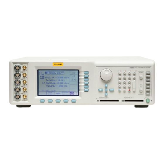
Page 28: Introduction To The Front Panel
Tektronix CG5011 and SG5030 calibrators. Refer to Section 6. • Semi-automatic operation using procedure memory cards to drive the 9500B, with control of the subject UUT being implemented by a form of the UUT manufacturer's procedure through a series of user prompts. Refer to Section 5. -
Page 29: Connections
3.2.2.6 Power On/Off Switch Line power to the 9500B is switched On and Off using a switch at the left of the instrument, on the rear panel. Up is On; Down is Off. Descriptions assume 9500B/1100 Section 3: Model 9500B Controls: Modes of Operation... -
Page 30: Modes Of Operation
3.2.3 Output Controls Ensure that the 9500B is installed and switched on as in Section 2. If, The aim of this discussion is to become familiar with the 9500B after selecting Manual mode, the display does not correspond to Fig. - Page 31 'Digit Edit' These forms of editing are also described in greater detail, with format. In this case the 9500B firmware will illustrations, in Section 4, sub-section 4.4. always impose the basic units (not multiples or sub-multiples).
- Page 32 Preference selections are non-volatile. Once a parameter has been set 1—2—5 and 1—2—2.5—4—5 factor steps. up as required, it will be remembered by the 9500B through changes of mode and function, also being restored after Power down / Power up.
- Page 33 'UUT Error'. This permits use of the deviation control to adjust the 9500B output until the UUT oscilloscope presentation itself shows the required value. The 9500B output value can be read off, but in addition, the UUT's error is presented on the 9500B screen.
- Page 34 The five modes are: PROC = Procedure Mode: For calibration of a specific type of UUT, the sequence of 9500B output selections is determined by a 'Procedure' memory card, placed in the left-hand PCMCIA SLOT 1 beneath the panel outline. Results can be printed, or recorded in a second 'Data' card, placed in the right-hand PCMCIA SLOT 2.
- Page 35 MORE screen key on the of other parameters. Refer to para 3.4.3.14. right of the bottom row. The 9500B will transfer to the 'Password Entry' screen: 3. When you enter your password using the...
- Page 36 The default value is shown: can be changed by using to the 9500B using an address code, which can direct editing only. be a number in the range 0-30. For the 9500B DEFAULT Configuration 100 V to respond, this number must be matched by 5 Ø...
- Page 37 Procedure mode and Manual mode. DESK JET 2nd address inactive Use the softkeys to select The 9500B cannot be made to power-up in any another. other mode. Change by direct edit only. USER To set the power-up default mode use the...
- Page 38 'Enter new calib password' • to enter Calibration mode (for calibration screen: screen: of the 9500B itself). Refer to para 3.4.2. When the 9500B is shipped Configuration Configuration from new, the password requirement is enabled to avoid unauthorized access (refer to para 3.4.2).
- Page 39 20MHz in 1MHz steps, from a TTL source. 1MHz or 10MHz, from a 50Ω source (VSWR Our representation shows the current date < 1.2 to 100MHz). This can use the 9500B 1. On the 'Present Settings' screen, press the from a previous setting:...
- Page 40 Information only Reporting Pressing the 'HEAD CONFIG' key provides a The 9500B default language is English. It is screen which indicates the type, serial no., cal possible to change the language used in For users who wish to know when a UUT is...
- Page 41 Subsequently, during each verification in transfers to 'The result card requirement' and 'Measurement Type' blocks. Procedure mode, the 9500B will detect its own menu screen. The additional notes can be added on a screen slewed output and place the UUT measurement The power-on default is DISABLE.
- Page 42 'Present settings' right: list. TODAY'S DATE TIME EXIT 4. The EXIT screen key reverts to the PAGE SETUP screen without changing the start CERT DETAILS Screen Layout page number. 3-16 Section 3: Model 9500B Controls: Modes of Operation Descriptions assume 9500B/1100...
- Page 43 Enter a new message: the right. 3. The EXIT key reverts to the CERT TODAY'S DATE TIME EXIT DETAILS screen. Descriptions assume 9500B/1100 Section 3: Model 9500B Controls: Modes of Operation 3-17...
- Page 44 *IDN? it may be necessary to configure your user's name can be selected to appear on the On the second “Present Settings” menu “Fluke 9500B” to respond as a previous model certificate. New names can be added to the screen, press the CAL Alarm key on the “9500”...
- Page 45 4.17.5 Input Leakage Operation ......4.17-1 4.12.3 Menu Selections ........4.12-1 4.7 Edge Function 4.17.6 Using the 9500B to Test the Input Leakage Current 4.12.4 Linear Ramp Operation ......4.12-1 4.7.1 Introduction ..........4.7-1 of a UUT Oscilloscope ........ 4.17-2 4.12.5 Using the 9500B Linear Ramp Function for...
- Page 46 This page deliberately left blank This page deliberately left blank...
- Page 47 This sub-section deals with the Active Head Narrow Triangle waveform), timing Two connections are used for each head. An Technology™ used to connect the 9500B to a and levels originate in the mainframe and 18-way connector and cable provides power...
-
Page 48: Ref Frequency Input
4.2.3 AUX IN (Rear Panel) Despite the huge flexibility if the 9500B, it is sometimes desirable to apply signals from user's equipment to the inputs of a UUT oscilloscope, for specific calibration or test purposes. With the 9500B Auxiliary Input selected, wideband passive routing is available from a rear-panel 50Ω... -
Page 49: Manual Mode - Function Selection
WAVE CHANNEL 1.Ø FORM SELECT (N.B. The 9500B can be made to default to : Timing Markers. Select either Manual or Procedure mode at power- Fig. 4.3.3.2 Manual Mode Power-Up Waveform, Amplitude and up (refer to para 3.4.3.6: 'Power-up mode'). - Page 50 Descriptions assume 9500B/1100 4.3-2 Section 4: Using the Model 9500B — Function Selection...
-
Page 51: Edit Facilities
'triangular' cursor and the numeric keypad. ∆% ∆V TODAY'S DATE TIME WAVE CHANNEL 1.Ø FORM SELECT continued overleaf → Fig. 4.4.2 Typical Screen in Direct Mode Descriptions assume 9500B/1100 Section 4: Using the Model 9500B — Edit Facilities 4.4-1... -
Page 52: Direct Mode
Fig. 4.4.7 Result of Pressing ↵ (Enter) Numeric Entry facility employs the numeric SIGNAL CH1 5ØΩ Note that the 9500B has assumed that the typed keypad to enter whole values, where this is TRIGGER NONE characters '10' represent a deviation of +10.00% more convenient than operating on individual Amplitude = 2Ø.ØØØ... - Page 53 CHANNEL been avoided by typing '2', then pressing the 1.Ø FORM SELECT 'mV' screen key to obtain the correct result Fig. 4.4.11 Direct Mode Starting Point (Fig.4.4.10): Descriptions assume 9500B/1100 Section 4: Using the Model 9500B — Edit Facilities 4.4-3...
-
Page 54: Scope Mode
2.00mV (always assuming that the sequence 1→2→5 has been selected in 'Pref' facility). All other values with barred cursors will also be incremented in the preferred sequence. 4.4-4 Section 4: Using the Model 9500B — Edit Facilities Descriptions assume 9500B/1100... -
Page 55: Dc/Square Function
Low Voltage (LV) and channel has been nominated. High Voltage (HV) States ....4.5-5 between 10.000Hz and 100.00kHz. Frequency 4.5.6 Using the 9500B Square Function to Calibrate the Pressing the ' EXIT ' key will revert back to the has defaulted to 1kHz, deviation '∆' to zero, Amplitude Response of a UUT Oscilloscope ... - Page 56 50Ω will always be expected. 4.5-2 Section 4: Using the Model 9500B — DC/Square Function Descriptions assume 9500B/1100...
- Page 57 4.5.4 (DC/Square Operation) in the top left corner: paras 4.5.5/6 (Square Operation) paras 4.5.7/8 (DC Operation). Descriptions assume 9500B/1100 Section 4: Using the Model 9500B — DC/Square Function 4.5-3...
-
Page 58: Dc/Square Operation
Press to change display from Period Provided they do not exceed the output voltage limits shown, the contributors have the following to Frequency (not DC). adjustments (Scope mode): 4.5-4 Section 4: Using the Model 9500B — DC/Square Function Descriptions assume 9500B/1100... - Page 59 Low and High Voltage States Units/Division down to 10µV/div, unless the output voltage would fall below 35.52µV p-p (both 50Ω and 1MΩ loads). continued overleaf → Descriptions assume 9500B/1100 Section 4: Using the Model 9500B — DC/Square Function 4.5-5...
-
Page 60: Square Operation
4.5.5 Square Operation 4.5.6 Using the 9500B Square Function to Calibrate the Amplitude (Contd.) Response of a UUT Oscilloscope 4.5.5.3 Low Voltage (LV) and High 4.5.6.1 Introduction Voltage (HV) States Sequence of Operations (Contd.) Two types of procedures for amplitude... - Page 61 Guide. The following procedure assumes that the Follow the sequence of calibration stages as 9500B instrument is in Manual Mode. It is also directed by the guide, and carry out the assumed that the user will be familiar with the following operations (1) to (6) at each stage.
-
Page 62: Dc Operation
The 9500B is capable of simultaneous DC 5ØΩ 1MΩ CHANNEL the O/P Amplitude value. Output from all channels that have a 9510, 9520, 9530 or 9560 Active Head fitted. 4.5-8 Section 4: Using the Model 9500B — DC/Square Function Descriptions assume 9500B/1100... -
Page 63: Using The 9500B Dc Function To Calibrate The Amplitude Response Of A Uut Oscilloscope
4.5.8 Using the 9500B DC Function to Calibrate the Amplitude Whenever the DC waveform is selected within the DC/Square function an extra Soft Key is Response of a UUT Oscilloscope available in the CHANNEL SELECT sub 4.5.8.1 Introduction 4.5.8.3 UUT Scope: Amplitude menu. - Page 64 4.5.8 Using the 9500B DC Function to Calibrate the Amplitude Response of a UUT Oscilloscope (Contd.) 4.5.8.4 UUT Scope — Amplitude 1. 9500B 1. 9500B Calibration using the 9500B Use the front panel controls to set the 9500B Use the front panel controls to set the 9500B...
-
Page 65: Sine Function
Frequency to Period. except on recovery from a standby period, it will appear with the following default settings: Press to change display from Period to Frequency. Descriptions assume 9500B/1100 Section 4: Using the Model 9500B — Sine Function 4.6-1... -
Page 66: Menu Selections
'=' sign. Frequency and back to the Units/Division. Preferences key) (paras 4.4.1/2). The type of cursor at each position indicates the type of adjustment possible to that value. 4.6-2 Section 4: Using the Model 9500B — Sine Function Descriptions assume 9500B/1100... - Page 67 Again effectiveness will be limited by remaining path length and capacitance within the UUT. In all cases frequencies above 500MHz are not recommended for use into UUT input Descriptions assume 9500B/1100 Section 4: Using the Model 9500B — Sine Function 4.6-3...
-
Page 68: Dual Channel Operation
TODAY'S DATE TIME can be set: LOAD TRIGGER EXIT 5ØΩ 1MΩ CHANNEL Now press the DUAL CHANNEL soft key, and the Dual Channel screen icon will appear. 4.6-4 Section 4: Using the Model 9500B — Sine Function Descriptions assume 9500B/1100... -
Page 69: Using The 9500B Levelled Sine Function To Calibrate The Flatness/Bandwidth Response Of A Uut Oscilloscope
4.6.6 Using the 9500B Levelled Sine Function to Calibrate the Flatness/Bandwidth Response of a UUT Oscilloscope 4.6.6.1 Introduction 4.6.6.4 4.6.6.5 UUT Scope — Flatness Calibration UUT Oscilloscope — Flatness Two types of procedures for flatness and using the 9500B as a Fixed Source... - Page 70 4.6-6 Section 4: Using the Model 9500B — Sine Function Descriptions assume 9500B/1100...
-
Page 71: Default Settings
∆% ∆V function. Refer to paras 4.5.3. 4.7.5.1 Introduction ........4.7-3 percent of set value. 4.7.6 Using the 9500B Edge Function to Calibrate the Pulse Response of a UUT Oscilloscope ..4.7-4 Cursor on Frequency/Period: 4.7.3.1 Retained Channel Memory 4.7.6.1 Introduction ........ -
Page 72: Menu Selections
( ), ( ) and ( keys. The keys are defaults: High Edge: 5V, others: 1V). inactive. 4.7-2 Section 4: Using the Model 9500B — Edge Function Descriptions assume 9500B/1100... - Page 73 Square function (refer to para Output Voltage (Scope and Direct Mode) 4.5.5.3). The threshold-setting limits are ±10Vpk-pk and ±110Vpk-pk. The O/P Amplitude is only adjustable by means of its contributors. Descriptions assume 9500B/1100 Section 4: Using the Model 9500B — Edge Function 4.7-3...
-
Page 74: Using The 9500B Edge Function To Calibrate The Pulse Response Of A Uut Oscilloscope
4.7.6 Using the 9500B Edge Function to Calibrate the Pulse Response of a UUT Oscilloscope 4.7.6.1 Introduction 4.7.6.4 UUT Scope — Pulse Response Calibration using Two types of procedures for pulse response the 9500B as a Fixed calibration use the 9500B as a fixed source,... -
Page 75: Time Markers Function
O/P Amplitude = 1.ØØØØ V pk-pk operate in the same way as in DC/Square function. Refer to paras 4.5.3. TODAY'S DATE TIME WAVE CHANNEL 1.Ø FORM SELECT Descriptions assume 9500B/1100 Section 4: Using the Model 9500B — Time Markers Function 4.8-1... -
Page 76: Time Markers Operation
100mV - 1V 621.32ns -45% +45% 900.91ns 100mV - 1V 13.794ns -45% +45% 20.000ns 100mV - 1V 621.32ns -45% +45% 20.000ns 100mV - 1V 621.32ns -45% +45% 20.000ns 4.8-2 Section 4: Using the Model 9500B — Time Markers Function Descriptions assume 9500B/1100... - Page 77 100mV p-p and 1V p-p. With Marker Style , for sinewave periods less than 909.09ps, the maximum output voltage available is 500mVp-p. Descriptions assume 9500B/1100 Section 4: Using the Model 9500B — Time Markers Function 4.8-3...
-
Page 78: Using The 9500B Time Markers Function To Calibrate The Time Base Of A Uut Oscilloscope
4.8.5 Using the 9500B Time Markers Function to Calibrate the Time Base of a UUT Oscilloscope 4.8.5.1 Introduction 4.8.5.4 4.8.5.5 UUT Scope — Time Base Calibration UUT Scope — Time Base Calibration, Two types of procedures for time base using the 9500B as a Fixed Source... -
Page 79: Selection Of Auxiliary Functions
Short/Open Output. 4.17 'Aux' key is pressed, the system defaults to ➞ Pulse Width 4.18 show the Auxiliary menu screen: Auxiliary Functions AUX IN TODAY'S DATE TIME ➞ Descriptions assume 9500B/1100 Section 4: Using the Model 9500B — Auxiliary Functions 4.9-1... - Page 80 This page deliberately left blank This page intentionally left blank...
-
Page 81: Current Function
4.10.8 DCI Operation ..........4.10-5 4.10.8.1 Polarity ......... 4.10-5 4.10.8.2 Value Editing ........ 4.10-5 4.10.8.3 Output Current Editing ....4.10-5 4.10.9 Using the 9500B DCI Function to Calibrate the DC-Coupled Amplitude Response of a UUT Oscilloscope ........4.10-6 4.10.9.1 Introduction ........4.10-6 4.10.9.2 Interconnections...... -
Page 82: Menu Selections
4.10.5 (Current Operation) Frequency to Period (not DC). paras 4.10.6/7 (Square Operation) paras 4.10.8/9 (DCI Operation). Press to change display from Period to Frequency (not DC). 4.10-2 Section 4: Using the Model 9500B — Current Function Descriptions assume 9500B/1100... -
Page 83: Square Operation
'1, 2, 5' or are shown on the right side of the '=' sign. '1, 2, 2.5, 4, 5' as chosen using the Preferences key) (paras 4.4.1/2). continued overleaf → Descriptions assume 9500B/1100 Section 4: Using the Model 9500B — Current Function 4.10-3... -
Page 84: Using The 9500B Current (Square) Function To Calibrate The Pulse Response Of A Uut Oscilloscope Current Probe
4.10.6 Square Operation 4.10.7 Using the 9500B Current (Square) Function to Calibrate the (Contd.) Pulse Response of a UUT Oscilloscope Current Probe 4.10.6.2 Output Current Editing 4.10.7.1 Introduction 4.10.7.4 (Contd.) UUT Current Probe — Pulse Response Deviation (Scope and Direct Mode) -
Page 85: Dci Operation
Frequency = 1.ØØØØ kHz following operations (1) to (6) at each stage. Units/Division 20µA/div 50mA/div 1. 9500B Scaling Multiplier TODAY'S DATE TIME Use the front panel controls to set the 9500B Deviation -11.20% +11.20% WAVE CHANNEL 1.Ø FORM SELECT Output to the required square wave p-p current... -
Page 86: Using The 9500B Dci Function To Calibrate The Amplitude Response Of A Uut Oscilloscope Current Probe
4.10.9 Using the 9500B DCI Function to Calibrate the Amplitude Response of a UUT Oscilloscope Current Probe 4.10.9.1 Introduction 4.10.9.4 7. Calibration UUT Current Probe — Amplitude Two types of procedures for amplitude a. If a calibration adjustment is provided,... - Page 87 (1) to (8) at each stage. 1. 9500B Use the front panel controls to set the 9500B Output to the required DC current and polarity for the UUT Probe amplitude cal point: 2.
- Page 88 This page intentionally left blank This page deliberately left blank...
-
Page 89: Composite Video Function
(paras Note: Without Option 5, only one signal 4.5.3). channel and one trigger channel is available. 4.11.4.1 Retained Channel Memory Refer to para 4.5.3.6. Descriptions assume 9500B/1100 Section 4: Using the Model 9500B — Composite Video Function 4.11-1... -
Page 90: Composite Video Function Operation
1. 9500B Video Inversion a. Use an active head to connect from the Use the front panel controls to set the 9500B to Composite Video can be toggled between required 9500B channel output to the video output the required Luminance level, upright and inverse, using the +/- screen key. -
Page 91: Linear Ramp Function
Whenever the Linear Ramp menu screen is opened, except on recovery from a standby Ramp Time Waveform Period period, it will appear with the following default settings: 100ms 300ms 10ms 30ms Descriptions assume 9500B/1100 Section 4: Using the Model 9500B — Linear Ramp Function 4.12-1... -
Page 92: Using The 9500B Linear Ramp Function For Error Code Detection And Trigger Level Marker Checks
Set Output OFF. function, press the 'Aux' key on the right of the 'OSCILLOSCOPE CALIBRATOR' panel, then the soft key on the right of the screen. 4.12-2 Section 4: Using the Model 9500B — Linear Ramp Function Descriptions assume 9500B/1100... -
Page 93: Overload Pulse Function
Sync or 100Hz triggers are provided TRIG to trigger the UUT oscilloscope channel and one trigger channel is if required. continuously. available. continued overleaf → Descriptions assume 9500B/1100 Section 4: Using the Model 9500B — Overload Pulse Function 4.13-1... -
Page 94: Overload Pulse Operation
4.13.5 Overload Pulse 4.13.6 Using the 9500B to Test the Overload Response of a UUT Operation Oscilloscope (Contd.) 4.13.5.4 Value Editing 4.13.6.1 Introduction 4.13.6.4 Sequence of Operations The test procedure consists of inputting a single Overload Protection Different oscilloscope manufacturers have... -
Page 95: Zero Skew Function
1, 2 and 3 had heads attached, nothing was fitted to channel 4, and a trigger cable was fitted to channel 5. continued overleaf → Descriptions assume 9500B/1100 Section 4: Using the Model 9500B — Zero Skew Function 4.14-1... -
Page 96: Menu Selections
9500B will recognize the new head as being unaligned, and will not allow it to be used until another precision aligment has been carried out. 4.14-2 Section 4: Using the Model 9500B — Zero Skew Function Descriptions assume 9500B/1100... -
Page 97: Measurement Of Uut Oscilloscope Channel Skew
UUT Oscilloscope screen. Manufacturer's Test Guide. Ensure that the required channels are selected 5. 9500B Set Output OFF. and, if necessary, have been 'Precision Aligned'. Descriptions assume 9500B/1100 Section 4: Using the Model 9500B — Zero Skew Function 4.14-3... - Page 98 This page deliberately left blank This page deliberately left blank...
-
Page 99: Auxiliary Input
Menu Selections 4.15.2 Automated Routing Signal Channel selection, Trigger Channel Despite the huge flexibility if the 9500B, it is selection, Cable selection and Trigger Ratio all sometimes required to apply signals from user's operate in the same way as in DC/Square equipment to the inputs of a UUT oscilloscope, function. -
Page 100: Using The 9500B For Automated Routing Of User-Specific Calibration Signals To Uut Oscilloscope Input Channels
Setup 3. 9500B Set Output ON. The following procedures assume that the 9500B instrument is in Manual Mode. It is also 4. UUT 'Scope assumed that the user will be familiar with a. Adjust the sweep speed and trigger level front panel operation. -
Page 101: Load Resistance And Capacitance Measurement
Load Capacitance screen. No triggers are provided. Ø.ØØØ pF TODAY'S DATE TIME SIGNAL CHANNEL Descriptions assume 9500B/1100 Section 4: Using the Model 9500B — Load R and C Measurement 4.16-1... -
Page 102: Use The 9500B To Measure Load Resistance Or Load Capacitance
Record the UUT channel load resistance at the 5. 9500B Set Output OFF. test point as detailed in the UUT Oscilloscope Manufacturer's Test/Calibration Guide. 5. 9500B Set Output OFF. 4.16-2 Section 4: Using the Model 9500B — Load R and C Measurement Descriptions assume 9500B/1100... -
Page 103: Input Leakage Function
4.17.5.2 Open Circuit Output Leakage UUT Input Leakage Test Specification ........ 4.17-1 TRIG to trigger the UUT oscilloscope. 4.17.6 Using the 9500B to Test the Input Leakage Current of a UUT Oscilloscope ........4.17-2 4.17.5.2 Open Circuit Output 4.17.6.1 Introduction ........4.17-2 Leakage Specification 4.17.6.2 Interconnections ...... -
Page 104: Using The 9500B To Test The Input Leakage Current Of A Uut Oscilloscope
4.17.6 Using the 9500B to Test the Input Leakage Current of a UUT Oscilloscope 4.17.6.1 Introduction 4.17.6.4 Sequence of Operations The test procedure consists of applying an open-circuit and short-circuit to each channel Refer to the table or list of UUT Oscilloscope... -
Page 105: Pulse Width Function
The Pulse Width function is accessed by first pressing the “Aux” key on the right of the “OSCILLOSCOPE CALIBRATOR” panel, then pressing the soft key on the lower ➞ right of the screen. Descriptions assume 9500B/1100 Section 4: Using the Model 9500B — Pulse Width Function 4.18-1... - Page 106 4.18-2 Section 4: Using the Model 9500B — Pulse Width Function Descriptions assume 9500B/1100...
- Page 107 5.3 Procedure mode — Access Guide. 5.3.1 Introduction ............ 5.3-1 5.3.2 Mode Selection ..........5.3-1 5.3.3 Selection of Procedure Mode — Entry Menus Common to All Procedures ......5.3-1 Descriptions assume 9500B/1100 Section 5: Using the Model 9500B — Procedure Mode — Contents 5.1-1...
- Page 108 This page deliberately left blank This page intentionally left blank...
- Page 109 Even if the program has locked up, this button is effective in cutting off the output. continued overleaf → Descriptions assume 9500B/1100 Section 5: 9500B Procedure Mode - Safety and General Notes 5.2-1...
- Page 110 Enable Printing Printing must be enabled, using the Config mode screen keys 'PRINTER' and the appropriate selection of printer type (refer to Section 3, paras 3.4.3.5). 5.2-2 Section 5: 9500B Procedure Mode - Safety and General Notes Descriptions assume 9500B/1100...
- Page 111 If this is less than 150% of the procedure's estimated results requirement, the user will be warned to insert a different card. Descriptions assume 9500B/1100 Section 5: 9500B Procedure Mode - Safety and General Notes 5.2-3...
- Page 112 This page deliberately left blank This page intentionally left blank...
- Page 113 When Procedure mode has been successfully the words. entered, the 9500B starts by presenting the Only UPPER CASE characters are available 'Select USER NAME ...' display: from the keypad. Descriptions assume 9500B/1100 Section 5: 9500B Procedure Mode - Access Guide 5.3-1...
- Page 114 Refer to paras 5.3.3 13, Fig 5.3.2. recent power-on, a UUT model was selected The 68-way socket pins can be seen on the end from the Select Model screen menu, the 9500B of the card to be inserted: will have downloaded all the procedures for the selected model into internal RAM.
- Page 115 Model enter the UUT serial number. Pressing the (Only available if more than one 'OK' screen key will cause the 9500B to transfer By the time the 'Select MODEL' screen has manufacturer is listed in the to the 'Serial Number' screen.
- Page 116 1 Year Verification This is a variant of 1 Year Verification, different program other Model 9500B units. ISO9000 Verify in that the 9500B provides a wider range of test Verify Pass/Fail Procedure Activation points to verify performance in greater detail...
- Page 117 For the choices obtained from the five screen continued overleaf → keys, refer to paras 5.3.3.12. Pressing OK will cause the 9500B to pass on to the next operation in sequence, only after the appropriate heads have been connected to the selected channels.
- Page 118 It is assumed that the same unit is being tested, so the same serial number will appear on any results print- out. 5.3-6 Section 5: 9500B Procedure Mode - Access Guide Descriptions assume 9500B/1100...
- Page 119 About Section 6 Section 6 describes the environment in which the Model 9500B will operate in remote applications, using the SCPI (Standard Commands for Programmable Instruments) language, within the IEEE-488.1 remote interface. In Section 6 we shall show how the 9500B adopts the IEEE- 488.2 message-exchange model and reporting structure, and define the SCPI commands and syntax used to control the 9500B.
- Page 120 This page deliberately left blank This page deliberately left blank...
- Page 121 9500B SCPI Subsystems Page: CALibration Used to calibrate the functions and hardware ranges of the 9500B, correcting for system errors which have accumulated due to drift and ageing effects: ........................6.6-2 SECure :PASSword. Gains access to Calibration operations, using 'Cal Enable' switch and Password. .. 6.6-2 :EXIT.
- Page 122 Page: 6.2.2 9500B SCPI Subsystems (Contd.) [SOURce] Used to select the main 9500B Function to be output: ......................6.6-7 :FUNCtion Selects the Waveshape of output signals ..................6.6-8 :SCOPe Backward compatibility with 9100 Opt. 250 ................... 6.6-8 [:SHAPe](?) Selects the Waveshape of output signals ........6.6-8 :TRANsition(?) Selects the direction of the important edge .........
- Page 123 0 to 30 inclusive. They in the publications ANSI/IEEE Std. 488.1- cannot be made to respond to any address The codes which apply to the 9500B are given 1987 and IEEE Std. 488.2-1988. outside this range. Secondary addressing is in table 6.1, together with short descriptions.
- Page 124 Conformance of the 9500B remote Data Valid programming commands to SCPI ensures that NRFD Not Ready For Data the 9500B has a high degree of consistency with other conforming instruments. For most NDAC Not Data Accepted specific commands, such as those relating to...
- Page 125 9500B. The 9500B is always aware of its stored address, responding to Talk or Listen commands from the controller at that address. When the address is changed by the user, the 9500B recognizes its new address and ignores its old address, as soon as it is stored by the user pressing the EXIT key in the Configuration —...
- Page 126 However, 'Test' can be run remotely. • interrupt analog output; • interrupt or affect any functions of the device not associated with the IEEE 488 system; 6.4-2 Section 6: 9500B System Operation — Using the 9500B in a System...
- Page 127 (PON bit) Parser or Execution Control, the buffer will progressively fill up. When the buffer is full, Fig. 6.1 9500B Message Exchange Model the handshake is held. Section 6: 9500B System Operation — Using the 9500B in a System 6.4-3...
- Page 128 Available - MAV) of the Status Byte register. Bit 4 is set false when the output queue is empty (refer to Sub-Section 6.5 ‘Retrieval of Device Status Information’). 6.4-4 Section 6: 9500B System Operation — Using the 9500B in a System...
- Page 129 Byte also to be set true. If this bit is enabled, then the Status Byte bit 6 (MSS/RQS) will be set true, and the 9500B will set the IEEE-488 bus SRQ line true. continued overleaf → Section 6: 9500B System Operation — Retrieval of Device Status Information 6.5-1...
- Page 130 0 Queue the Output Queue) QUEStionable: ∗ ESR? ∗ ESE? ENABle ? QUEStionable: QUEStionable: ∗ ESE phs Nrf EVENt ? ENABle <DNPD> Fig. 6.2 9500B Status Reporting Structure 6.5-2 Section 6: 9500B System Operation — Retrieval of Device Status Information...
- Page 131 Bit 3 summarizes the state of the ‘Questionable is described in Sub-Section 6.5.4. Status data’, held in the ‘Questionable Status register’ (QSR), whose bits represent SCPI- continued overleaf → Section 6: 9500B System Operation — Retrieval of Device Status Information 6.5-3...
- Page 132 Request Control (RQC) available in the output queue, then Nrf should The common command ∗ CLS clears the queue. This bit is not used in the 9500B. It is always be set to 48. The binary decode is 00110000 so set false.
- Page 133 00011000 so bit 3 or bit 4, when true, restored at power on. will set the ESB bit true; but when bits 0-2, or 5-7 are true, the ESB bit will remain false. Section 6: 9500B System Operation — Retrieval of Device Status Information 6.5-5...
- Page 134 Event Register. All registers (Event, Enable and Condition) can be interrogated by appropriate 'Queries' to divulge their bits' states. 6.5-6 Section 6: 9500B System Operation — Retrieval of Device Status Information...
- Page 135 ( | ) can be read as "or" and is used to separate alternative parameter <cpd>{CH1|CH2|CH3|CH4|CH5} options. The response from this query will be one of the parameters listed in association with the command. Section 6: 9500B System Operation — SCPI Language — Commands and Syntax 6.6-1...
- Page 136 'Calibration' password registered in the 9500B software. The calibration password can be changed only in Configuration First, there is a switch on the 9500B itself that must be set to CAL ENABLE. Having done this, the calibration password command must mode from the 9500B front panel (Refer to Section 3).
- Page 137 Once a target has been set, the 9500B adjustment is restricted to values 6.6.2.9 CAL:SPEC:FADJust within the selected hardware voltage span and frequency band. In order Purpose to release this restriction, one of the following commands must be sent: This command selects the adjustment facility to allow the frequency TRIG? , EXIT or a new TARG command generation of the instrument to be calibrated.
- Page 138 OFF or 0 will set the output off Response to Query Version The 9500B will return ON if output is on, or OFF if output is off. 6.6-4 Section 6: 9500B System Operation — SCPI Language — Commands and Syntax...
- Page 139 Response to Query Version This query command returns the type, serial number, date last calibrated The 9500B will return 50 if 50Ω is selected, or 1E6 if 1MΩ is selected. and calibration due date of the active head fitted to the <cpd> channel.
- Page 140 Response to Query Version This dual mode is cancelled on receipt of a ROUTe:SIGNal <cpd> The 9500B will return 50 if 50Ω is selected, or 1E6 if 1MΩ is selected. command or on selection of another function. Both signals must have the same expected impedance. It is not possible 6.6.4.9...
- Page 141 6.6.5 SOURce Subsystem 6.6.5.1 SOURce Subsystem Table (Contd.) This subsystem is used to select the sources of 9500B output . The following are standard 9500B commands: Note about backward compatibility with programs written for Keyword Parameter Form the Model 9100 plus Option 250:...
- Page 142 ‘NONE’ will be returned. <cpd>SYMM sets the output square wave symmetrically about ground. Response to Query Version The instrument will return POS, NEG or SYMM as programmed. 6.6-8 Section 6: 9500B System Operation — SCPI Language — Commands and Syntax...
- Page 143 For details of local operation and parameter limitations, refer earlier to Section 4, Sub-Section 4.8 (Time Marker Function). Response to Query Version The instrument returns the <cpd> for the presently-selected waveform. Section 6: 9500B System Operation — SCPI Language — Commands and Syntax 6.6-9...
- Page 144 A settings conflict error will be reported if LINE marker waveshape is been selected or if Output is not already ON. selected. The EXECute command is not buffered in the 9500B. It will be ignored and discarded if a current EXECute command is not completed <cpd>...
- Page 145 The instrument will return the <cpd> for the currently-selected trigger 4, Sub-Section 4.11 (Composite Video Function). type. Response to Query Version The instrument will return the rounded <dnpd> for the currently- selected line frequency standard. Section 6: 9500B System Operation — SCPI Language — Commands and Syntax 6.6-11...
- Page 146 The instrument will return the <cpd> for the currently-selected open/ 4, Sub-Section 4.11 (Composite Video Function). short circuit state. Response to Query Version The instrument will return the <cpd> for the currently-selected amplitude level. 6.6-12 Section 6: 9500B System Operation — SCPI Language — Commands and Syntax...
- Page 147 50Ω. >55 is rounded to select 1MΩ. Response to Query Version The instrument will return the rounded <dnpd> for the currently- selected UUT input impedance. Section 6: 9500B System Operation — SCPI Language — Commands and Syntax 6.6-13...
- Page 148 The SPERiod command is used for backward compatibility with command. Option 250 in the 9100. In the 9100, the SPER command was available only in Edge and Timing Markers functions, but in the 9500B, the PER <dnpd> command is available in all applicable functions.
- Page 149 In the case of successfully measuring the resistance value of the UUT, 'no device trigger capability'.) this command will return a number within the approximate range of 10 to 150 or 50E3 to 20E6 depending on the setting of the 9500B channel 6.6.6.1 CONFigure[:RESistance|CAPacitance] impedance.
- Page 150 For example (refer to Fig. 6.2): response to the query therefore represents an instantaneous If the 9500B had just performed a selftest, the 'TESTING' bit 8 of 'Snapshot' of the register state, at the time that the query was the register would be set, and if no other Operation Event bits were accepted.
- Page 151 Purpose in the 9500B enable only the 'RESISTANCE' and 'CAPACITANCE' bits 12 and In the 9500B, the functions of the 'Transition' registers are not required, 11 of the Questionable Event register. so no access is given. The PRES command therefore affects only the...
- Page 152 The Error Queue Possible Formats As errors in the 9500B are detected, they are placed in a 'first in, first out' The string must conform to the scheme: dd, mm, yyyy where the chosen queue, called the 'Error Queue'. This queue conforms to the format sequence agrees with that set locally in paras 3.4.3.12.
- Page 153 SYST:VERS? returns an <Nr2> formatted numeric value corresponding This string defines the present time, consisting of two 2-digit numbers, to the SCPI version number for which the 9500B complies. At the time separated by a hyphen. The numbers represent hour and minute, in that of writing, this will be 1994.0.
- Page 154 Parameter Form reference. The <dnpd> must be in the range 1.0E6 and 20.0E6. The REFerence 9500B will round the <dnpd> to the nearest MHz and uses this as the OUTPut frequency selection. For example a <dnpd> of 9.1000E6 would be :FREQuency(?) <dnpd>...
- Page 155 6.4-1, including the point in time when the 9500B recognizes a user-initiated address change. Appendix E to Section 6 describes the active and non- active settings at power-on. Appendix A to Section 6: 9500B System Operation — IEEE 488.2 Device Documentation Requirements 6-A1...
- Page 156 They are also described in Section 6, Appendix C 24. No representations are used for 'Infinity' and 'Not-a- Number'. 13. ∗CAL? is not implemented. 14. ∗DDT is not implemented. 6-A2 Appendix A to Section 6: 9500B System Operation — IEEE 488.2 Device Documentation Requirements...
- Page 157 The output queue and MAV bit will be cleared if ∗CLS Power On and Reset Conditions immediately follows a 'Program Message Terminator'; refer to Not applicable. the IEEE 488.2 standard document. Appendix C to Section 6: 9500B System Operation — IEEE 488.2 Common Commands and Queries 6-C1...
- Page 158 Reset has no effect. service request byte, for this data structure. 6-C2 Appendix C to Section 6: 9500B System Operation — IEEE 488.2 Common Commands and Queries...
- Page 159 The value returned, when converted to base 2 (binary), identifies Refer to Section 6; Subsection 6.5. the bits as defined in the IEEE 488.2 standard. Execution Errors: None Appendix C to Section 6: 9500B System Operation — IEEE 488.2 Common Commands and Queries 6-C3...
- Page 160 The final response in the string will be followed by the terminator: 6-C4 Appendix C to Section 6: 9500B System Operation — IEEE 488.2 Common Commands and Queries...
- Page 161 This query conforms to the IEEE 488.2 standard requirements. OPC? Response Decode: The value returned is always 1, which is placed in the output queue when all pending operations are complete. Appendix C to Section 6: 9500B System Operation — IEEE 488.2 Common Commands and Queries 6-C5...
- Page 162 LN = 1: indicates that enhanced multichannel DC is fitted standard specification. LN = 0: indicates that enhanced multichannel DC is not fitted Execution Errors: None. Power On and Reset Conditions Not applicable. 6-C6 Appendix C to Section 6: 9500B System Operation — IEEE 488.2 Common Commands and Queries...
- Page 163 SRQ on power up. Appendix C to Section 6: 9500B System Operation — IEEE 488.2 Common Commands and Queries 6-C7...
- Page 164 = newline with EOI Power On and Reset Conditions No Change. This data is saved in non-volatile memory at Power Off, for use at Power On. 6-C8 Appendix C to Section 6: 9500B System Operation — IEEE 488.2 Common Commands and Queries...
- Page 165 The data can be recalled using the ∗PUD? query. Power On and Reset Conditions Data area remains unchanged. Appendix C to Section 6: 9500B System Operation — IEEE 488.2 Common Commands and Queries 6-C9...
- Page 166 The final response in the string will be followed by the terminator: nl = newline with EOI 6-C10 Appendix C to Section 6: 9500B System Operation — IEEE 488.2 Common Commands and Queries...
- Page 167 IEEE 488.2 document. Power On and Reset Conditions Note that numbers will be rounded to an integer. Not applicable. Appendix C to Section 6: 9500B System Operation — IEEE 488.2 Common Commands and Queries 6-C11...
- Page 168 For the detail definition see the IEEE 488.2 standard document. There is no method of clearing this byte directly. Its condition relies on the clearing of the overlying status data structure. 6-C12 Appendix C to Section 6: 9500B System Operation — IEEE 488.2 Common Commands and Queries...
- Page 169 The failure codes can be found only by re-running the self test manually. Refer to Section 8. Appendix C to Section 6: 9500B System Operation — IEEE 488.2 Common Commands and Queries 6-C13...
- Page 170 IEEE-488.2 but has little relevance Power On and Reset Conditions to this instrument as there are no parallel processes requiring Not applicable. Pending Operation Flags. 6-C14 Appendix C to Section 6: 9500B System Operation — IEEE 488.2 Common Commands and Queries...
- Page 171 Questionable Status Enable Register Depends on state of ∗PSC • the 9500B is returned to 'Operation Complete Command Error Queue Empty until first error is Idle State' (OCIS); detected Appendix D to Section 6: 9500B System Operation — Device Settings after ∗ RST 6-D1...
- Page 172 Not applicable *SRE Nrf Not applicable *SRE? Response depends on state of *PSC *STB? Response depends on state of *PSC *TST? Not applicable *WAI Not applicable Appendix D to Section 6: 9500B System Operation — Device Settings after ∗ RST 6-D2...
- Page 173 :POLarity(?) ....POS :GROund(?) ....OFF :SKEW ......Inactive :ALIGnment(?) ....DEFault [SOURce] :VOLTage [:LEVEl] ...... 20mV :FREQuency [:CW|FIXed](?) ....1kHz All other settings remain unchanged. Appendix D to Section 6: 9500B System Operation — Device Settings after ∗ RST 6-D3...
- Page 174 This page deliberately left blank This page deliberately left blank...
- Page 175 This leads to the user-friendly concept of 'Precise Talker' and 'Forgiving Listener'. Appendix F to Section 6: 9500B System Operation — Emulation of Tektronix SG5030 and CG5010/5011 6-F1...
- Page 176 The IEEE-488 Interface Function Capability is the same as 2nd address inactive for the 9500B (SH1AH1T6L4SR1RL1PP0DC1DT0C0). Change by direct edit only. TODAY'S DATE TIME EXIT 6-F2 Appendix F to Section 6: 9500B System Operation — Emulation of Tektronix SG5030 and CG5010/5011...
- Page 177 For example, queries that report a ‘standard’ answer are mapped. '√' indicates that the command is mapped. Appendix F to Section 6: 9500B System Operation — Emulation of Tektronix SG5030 and CG5010/5011 6-F3...
- Page 178 Enables or disables the ability to generate an SRQ by pressing the ID button on the front panel. USEreq ON|OFF Returns the present status of the instrument ID SRQ. USEreq? USEREQ OFF 6-F4 Appendix F to Section 6: 9500B System Operation — Emulation of Tektronix SG5030 and CG5010/5011...
- Page 179 Sets number of edges generated for one slewing cycle. EDGE <NR1> √ Returns a code for the error condition. ERR < 9500B error number > ERR? Appendix F to Section 6: 9500B System Operation — Emulation of Tektronix SG5030 and CG5010/5011 6-F5...
- Page 180 <message unit> units/division and DUT percentage error after operator pressed the READ? CONTINUE key. Controls generation of SRQ when ID button is pressed. REM ON|OFF 6-F6 Appendix F to Section 6: 9500B System Operation — Emulation of Tektronix SG5030 and CG5010/5011...
- Page 181 Returns a version ID code. VERS? VERS 0000FFFF √ Sets the instrument to voltage and desired number of units/division. V/D <NR3>V Resets the shift counter to zero. ZSHF Appendix F to Section 6: 9500B System Operation — Emulation of Tektronix SG5030 and CG5010/5011 6-F7...
- Page 182 This page deliberately left blank This page deliberately left blank...
-
Page 183: Accuracy Specifications
Line Voltage 95V to 132V rms 209V to 264V rms Installation Cat II Line Frequency 48Hz to 63Hz Power Consumption <400 VA Line Fuse: 220/240V T5.0A 250V 20mm IEC127 100/120V T10.0A 250V Warm-up: 20 minutes Section 7: Model 9500B — Specifications... -
Page 184: Voltage Function Specifications
270Hz square wave, increasing to 3s for 0.01% at 10Hz (extends to 600ms max. if instruction crosses a safety threshold or if an Output On is involved) Note 1 Accuracy specification excludes variability of resistance losses in mating BNC or PC3.5 connectors. Section 7: Model 9500B — Specifications... -
Page 185: Edge Function
[1] For Edge amplitudes below 33mV, this specification applies in a 3GHz bandwidth. Edge speeds faster than 500ps are not recommended for 1MΩ input applications. The 9560 Head is restricted to 50Ω loads only. [2] Rise and Fall time definitions in accordance with IEC Standard 60469:1987. Section 7: Model 9500B — Specifications... - Page 186 900.91ns to 55s 900.91ns to 55s 450.5ps to 9.009ns for 9500B/1100 or 9500B/3200 909.1ps to 9.009ns for 9500B/600 180.19ps to 9.009ns for 9500B/3200 with 9560 Head Ranging: Time/div ranging 1, 2, 5 or 1, 2, 2.5, 4, 5 or continuously variable ±45%...
-
Page 187: Levelled Sine Function Specifications
2nd Harmonic <-35dBc; 3rd Harmonic <-40dBc in 12GHz Non & Sub Harm' Purity <-40dBc <6.0GHz: <-35dBc Frequencies above 500MHz are not recommended for 1M input applications. The 9560 Head is restricted to 50Ω loads only. For offsets >10kHz. Section 7: Model 9500B — Specifications... -
Page 188: Dual Sine Function Specifications
800k - 1.2M 1.2M - 12M ±0.5% ±0.1% ±0.5% ±0.5% ±0.1% ±0.5% Accuracy: (Not available via 9550 or 9560 Active Head) Capacitance Measurement: 1pF to 35pF 35pF to 95pF ±2% ±0.25pF ±3% ±0.25pF Accuracy: Section 7: Model 9500B — Specifications... -
Page 189: Pulse Width Function Specifications
20ns to 100ns <1ns Rise and Fall Time: 450ps (typical) < ±5% pk (typical) Aberrations: Width Stability: < 10ps pk-pk 10mins/1˚C Pulse Jitter: (wrt Trigger) < 5ps pk-pk Frequency: 1kHz to 1MHz Amplitude: 1V pk-pk into 50Ω Section 7: Model 9500B — Specifications... -
Page 190: Other Output Function Specifications
<±0.1% deviation over 10 - 90% Skew Temp Coef <0.2ps/˚C Ramp Time: 1ms, 10ms, 100ms or 1s Rise and Fall Time 450ps (typical) Relative Jitter <7ps pk-pk The 9560 Head is restricted to 50Ω loads only. Section 7: Model 9500B — Specifications... - Page 191 Reference Frequency Input (BNC) Output (BNC) Frequency Range: 1MHz to 20MHz 1MHz or 10MHz in 1MHz steps Level: (typical) 90mV - 1V pk-pk Into 50Ω : 1V pk-pk Into 1MΩ: 2V pk-pk ±50ppm Lock Range: Section 7: Model 9500B — Specifications...
-
Page 192: Trigger Output Specifications
Input Leakage, Auxiliary Input and Input Impedance functions have no related trigger output. Free running 100Hz signal provided No trigger provided in Pulse Width function Amplitude: 1Vpk-pk into 50Ω Rise and Fall Time: < 1ns < ±10% Aberrations: Source VSWR: 1.2:1 typ 7-10 Section 7: Model 9500B — Specifications... -
Page 193: Section 8 Model 9500B — Routine Maintenance And Test 8.1 About Section 8
About Section 8 Section 8 gives first-level procedures for maintaining a Model 9500B, performing the Selftest operations and dealing with their results. We shall recommend maintenance intervals, methods and parts, and detail the routine maintenance procedures. Section 8 is divided into the following sub- sections: 8.2 Routine Maintenance. -
Page 194: Routine Maintenance
Foam Filter days. Remove the filter for thorough cleaning symbol. 617020 Snap Rivet, Richco. SR4050B 5 at least once per year, immediately prior to Black Nylon routine calibration of the unit. Section 8: Model 9500B — Routine Maintenance and Test... -
Page 195: Firmware Upgrade
DISABLE c. Replace and secure the switch cover. 6 7 8 If an upgrade is required for your Model 9500B d. Remove the PC-Card, switch the unit(s), your Service Center will inform you 3. Insert the PC-Card: 9500B Power ON and wait for and provide the appropriate PC-Card. -
Page 196: Model 9500B Test And Selftest
For example: and an extra selection will be available: TODAY'S DATE TIME PROC MANUAL CONFIG CALIB TEST Section 8: Model 9500B — Routine Maintenance and Test... -
Page 197: Selftest Runs To Completion
Fluke Service Center, please ensure that you either: copy the details from the screen for all the reported failures, or: print out the results. TODAY'S DATE TIME VIEW Continued Overleaf → EXIT PRINT FAILS Section 8: Model 9500B — Routine Maintenance and Test... -
Page 198: Selftest At Power-On
The first normal action at power on is to show 8.3.4 Interface Test the Fluke logo, and then the 9500B will run a The interface test selectively checks the 9500B 8.3.4.2 Display Memory Checks fast selftest:... -
Page 199: Keyboard Checks
EXIT returns to the Interface 'Select test' menu your Fluke Service Center. screen. The 'Enter' Key (↵) returns to the Interface 'Select test' menu screen. Section 8: Model 9500B — Routine Maintenance and Test... -
Page 200: Memory Card Checks
For a re-chargeable card with a low battery, the DISPLAY Selftest MEMORY The 9500B first checks for the presence of the low/dead message may take several minutes to correct SRAM card. If there is no card in the clear after pressing OK. -
Page 201: Tracker Ball Checks
'Results Card' format. A new suspected that the 9500B is at fault, it is wise to the last direction shown does not correspond to message appears on the display: report the result to your Fluke Service Center. -
Page 202: Printing Selftest Results
AUTO_FEED_L Output Paper is automatically fed 1 line after printing. errors. Otherwise it is advisable to report the This line is fixed _H (high) by the 9500B to result to your Fluke Service Center. disable autofeed. ERROR_L... -
Page 203: Printing Setup
+14.25ØØØØ +15.75ØØØØ ERR % gives the achieved percentage of full tolerance for that test. FAILURES In this column a failure is shown by the figure '1' against the relevant test. Section 8: Model 9500B — Routine Maintenance and Test 8-11... - Page 204 This page deliberately left blank...
- Page 205 The common command *CLS clears the queue. ALWAYS: record the total message content for possible use by the Service Center. Appendix A to Section 8: 9500B Maintenance — Error Reporting Subsystem 8-A1...
- Page 206 Input Buffer is full, and the controller is waiting to send more data bytes to the device. ALWAYS: record the total message content for possible use by the Service Center. 8-A2 Appendix A to Section 8: 9500B Maintenance — Error Reporting Subsystem...
- Page 207 -9075, "Multi-channel DC requires 1M\352 impedance" -9076, "Outside Pulse Width range" -9077, "9560 Dual channel sine frequency restricted to 3.2GHz" ALWAYS: record the total message content for possible use by the Service Center. Appendix A to Section 8: 9500B Maintenance — Error Reporting Subsystem 8-A3...
- Page 208 1046, "CH2 Load mismatch detected: UUT <50k\352" 1047, "CH3 Load mismatch detected: UUT <50k\352" 1048, "CH4 Load mismatch detected: UUT <50k\352" ALWAYS: record the total message content for possible use by the Service Center. 8-A4 Appendix A to Section 8: 9500B Maintenance — Error Reporting Subsystem...
- Page 209 "WARNING: Head on channel 3 is past cal due date" 4212, "WARNING: Head on channel 4 is past cal due date" ALWAYS: record the total message content for possible use by the Service Center. Appendix A to Section 8: 9500B Maintenance — Error Reporting Subsystem 8-A5...
- Page 210 -7031, "Ref frequency must be within the range 0.1 Hz and 600 MHz" 9990, "Program ASSERTION Trip:" ALWAYS: record the total message content for possible use by the Service Center. 8-A6 Appendix A to Section 8: 9500B Maintenance — Error Reporting Subsystem...
-
Page 211: About Section 9
Section 7 of this handbook — i.e. the measurement equipment should and including National Standards. Its traceable accuracy figures are be able to operate within the relevant 9500B limits so that no additional quoted in the specifications given in Section 7, and all relate to a 1-year accuracy figures have to be taken into account. -
Page 212: Specification Limits
9.8.6 Pulse Width Function Verification Procedure The list of topics above are placed in the order in which the 9500B Suitability Mainframe functions should be verified. Although it is not essential to The procedures given in this section to verify the Model 9500B... - Page 213 Meas 1M Ω SQV 50 Ω Ref 1M Ω Ref 50 Ω 230 Vpk Meas 50k Ω Meas 50 Ω Ref 50k Ω 4955 CALIBRATION ADAPTOR Fig 9.8.1.1 DC/Square; DC Voltage Verification — Interconnections Section 9: Verifying the Model 9500B Accuracy Specification...
- Page 214 23.00577V c. Check that the Measured Value is +DC20 50.000V 49.98748V 50.01252V at or between the Absolute Tolerance Limits. +DC21 60.000V 59.98498V 60.01502V 6. 9500B Set Output OFF. +DC22 190.00V 189.9525V 190.0475V Section 9: Verifying the Model 9500B Accuracy Specification...
- Page 215 -DC15 2.3000V 2.2994V 2.3006V -DC16 5.0000V 4.99873V 5.00127V -DC17 6.0000V 5.99848V 6.00152V -DC18 19.000V 18.99523V 19.00477V -DC19 23.000V 22.99423V 23.00577V -DC20 50.000V 49.98748V 50.01252V -DC21 60.000V 59.98498V 60.01502V -DC22 190.00V 189.9525V 190.0475V Section 9: Verifying the Model 9500B Accuracy Specification...
-
Page 216: Verifying The Dc/Square Function: Square Voltage
Tables 9.8.2.1, 9.8.2.2 and 9.8.2.3. 9.8.2.2 Equipment Requirements • The UUT Model 9500B Mainframe, with 9510 or 9530 Active Head. • A high resolution Standards DMM with RMS AC Voltage accuracy of ±0.01% or better, from 2.5mV to 35V, at 1kHz. - Page 217 SQV 50 Ω Ref 1M Ω Ref 50 Ω 230 Vpk Meas 50k Ω Meas 50 Ω Ref 50k Ω 4955 CALIBRATION ADAPTOR Fig 9.8.2.1 DC/Square; Square Voltage Verification — Interconnections Continued overleaf → Section 9: Verifying the Model 9500B Accuracy Specification...
- Page 218 +SQ2 1kHz 60.000mV 59.93mV 60.07mV 29.99799mV 29.96mV 30.03mV +SQ3 1kHz 6.0000mV 5.984mV 6.016mV 2.999799mV 2.992mV 3.008mV +SQ4 1kHz 6.0000V 5.99399V 6.00601V 2.999799V 2.99674V 3.00275V +SQ5 1kHz 60.000V 59.93999V 60.06001V 29.99799V 29.96750V 30.02751V Section 9: Verifying the Model 9500B Accuracy Specification...
- Page 219 ± 1kHz 60.000mV 59.93mV 60.07mV 29.99799mV 29.96mV 30.03mV ± 1kHz 6.0000mV 5.984mV 6.016mV 2.999799mV 2.992mV 3.008mV ± 1kHz 6.0000V 5.99399V 6.00601V 2.999799V 2.99674V 3.00275V ± 1kHz 60.000V 59.93999V 60.06001V 29.99799V 29.96750V 30.02751V Section 9: Verifying the Model 9500B Accuracy Specification...
-
Page 220: Verifying The Lf Sine Voltage Function
Table 9.8.3.1. 9.8.3.2 Equipment Requirements • The UUT Model 9500B Mainframe, with 9510 or 9530 Active Head. • A high resolution Standards DMM with RMS AC Voltage accuracy of ±0.3% or better, between 0.5V and 2V, at 1kHz and 45kHz. - Page 221 Ref 1M Ω Ref 50 Ω 230 Vpk Meas 50k Ω Meas 50 Ω Ref 50k Ω 4955 CALIBRATION ADAPTOR Fig 9.8.3.1 LF Sine Voltage Verification — Interconnections Continued overleaf → Section 9: Verifying the Model 9500B Accuracy Specification 9-11...
- Page 222 1kHz 4.8000V 4.632V 4.968V 1.69706V 1.6377V 1.7565V SIN2 45kHz 4.8000V 4.632V 4.968V 1.69706V 1.6377V 1.7565V SIN3 1kHz 1.9000V 1.8335V 1.9665V 0.67175V 0.6482V 0.6953V SIN4 45kHz 1.9000V 1.8335V 1.9665V 0.67175V 0.6482V 0.6953V 9-12 Section 9: Verifying the Model 9500B Accuracy Specification...
-
Page 223: Verifying The Time Markers Function
Verification Setup Equipment requirements are given at para 9.8.4.2 and test 1. Connections Connect the 9500B to the Counter as shown in Para interconnections at para 9.8.4.3. 9.8.4.1, and ensure that both instruments are The Time Markers Function is verified by carrying out measurements powered ON and warmed up. - Page 224 Limits ( 0.25ppm) Period Period Lower Higher MKR1 10.000ns (sqr) 9.9999975ns 10.0000025ns MKR2 100.00ns (sqr) 99.999975ns 100.000025ns MKR3 1.0000µs (sqr) 0.99999975µs 1.00000025µs MKR4 1.0000ms (sqr) 0.99999975ms 1.00000025ms MKR5 10.000ms (sqr) 9.9999975ms 10.0000025ms 9-14 Section 9: Verifying the Model 9500B Accuracy Specification...
-
Page 225: Verifying The Load Resistance Measurement Function
Refer to Fig 9.8.5.1 (overleaf). 9.8.5.4 Verification Setup 1. Connections Ensure that the 9500B is connected to the Standards DMM as shown in Fig. 9.8.5.1, or via a similar BNC-4mm adaptor and 50Ω load, and that both instruments are powered on and warmed up. - Page 226 Ref 1M Ω Ref 50 Ω 230 Vpk Meas 50k Ω Meas 50 Ω Ref 50k Ω 4955 CALIBRATION ADAPTOR Ω Fig 9.8.5.1 Load Resistance Measurement Function Verification (1M Ref) — Interconnections 9-16 Section 9: Verifying the Model 9500B Accuracy Specification...
- Page 227 Set to the appropriate Resistance measurement 9. Press the ON key to turn the 9500B output on. range, take a Resistance measurement and note the 10. Using the 9500B, take a Resistance measurement and note the result result (R ref) in Table 9.8.5.1. R meas ) in Table 9.8.5.1.
-
Page 228: Verifying The Pulse Width Function
9.8.6.4 Verification Setup Equipment requirements are given at para 9.8.6.2 and test 1. Connections Connect the 9500B to the Counter as shown in Para interconnections at para 9.8.6.3. 9.8.4.1, and ensure that both instruments are The Pulse Width Function is verified by carrying out measurements of powered ON and warmed up. - Page 229 Please copy the following table. Enter the measurements in the approriate Measured Period column on the copy: Verif. Pulse Absolute Tolerance Measured ± ± Point. Width Limits ( 200ps) Duration Duration Lower Higher 4.0000ns 3.6000ns 4.4000ns 20.000ns 18.800ns 21.200ns 100.00ns 95.20ns 105.20ns Section 9: Verifying the Model 9500B Accuracy Specification 9-19...
- Page 230 Load Capacitance Measurement Function of amplitude at frequencies of 1kHz, 45kHz and 50kHz; in the sequences The list of topics above are placed in the order in which the 9500B Head given at para 9.9.1.4 and 9.9.1.5, at the verification points shown in functions should be verified.
- Page 231 Fig 9.9.1.1 LF Sine Voltage Verification — Interconnections 9.9.1.4 Verification Setup 1. Connections Ensure that the 9500B is connected to the DMM as 2. 9500B Ensure that the 9500B is in MANUAL mode and shown in Fig. 9.9.1.1, or via a similar PC3.5 or then select the Sine function ( key).
- Page 232 1.0000V 0.985V 1.015V 0.35355V 0.34825V 0.35885V SGN9 50kHz 300.00mV 295.5mV 304.5mV 106.066mV 104.475mV 107 .657mV SGN10 50kHz 100.00mV 98.50mV 101.5mV 35.3553mV 34.8250mV 35.8856mV SGN11 50kHz 30.000mV 29.55mV 30.45mV 10.6066mV 10.4475mV 10.7657mV 9-22 Section 9: Verifying the Model 9500B Accuracy Specification...
- Page 233 Equipment Requirements Equipment requirements are given at para 9.9.2.2 and test • The UUT Active Head, connected to a verified Model 9500B interconnections at para 9.9.2.3. Para 9.9.2.4 shows the Verification Mainframe (for Mainframe verification, refer to Sub-section 9.8.3). Setup.
- Page 234 Pk-Pk value of 9500B output voltage into 50Ω: • With this we must combine (by RSS Method) the 9500B pk-pk Pk-Pk Voltage = 20√(power into 50Ω) voltage flatness specification. At 10MHz, the 9500B specification c. Record the result in the ' Measured p-p Voltage relative to 50kHz is ±1.5%.
- Page 235 † SF08 725MHz ±3.5 † SF09 1GHz ±4.0 †† SF10 1.5GHz ±4.0 †† SF11 2GHz ±4.0 †† SF12 2.5GHz Additional verification points for: 9500B/1100 & 9500B/3200 (†); and 9500B/3200 ( ††). Section 9: Verifying the Model 9500B Accuracy Specification 9-25...
- Page 236 SF60 4GHz ±4.0 ††† SF61 5GHz ±4.0 ††† SF62 5.5GHz ±4.0 ††† SF63 6GHz †: Additional verification points for: 9500B/1100 & 9500B/3200 (†); 9500B/3200 only (††) and 9500B/3200 with 9560 (†††). 9-26 Section 9: Verifying the Model 9500B Accuracy Specification...
- Page 237 SF64 ††† 4GHz ±4.0 SF65 ††† 5GHz ±4.0 ††† SF66 5.5GHz ±4.0 ††† SF67 6GHz Additional verification points for: 9500B/1100 & 9500B/3200 (†); 9500B/3200 only (††) and 9500B/3200 with 9560 (†††). Section 9: Verifying the Model 9500B Accuracy Specification 9-27...
- Page 238 ††† SF68 4GHz ±4.0 ††† SF69 5GHz ±4.0 ††† SF70 5.5GHz ±4.0 ††† SF71 6GHz Additional verification points for: 9500B/1100 & 9500B/3200 (†); 9500B/3200 only (††) and 9500B/3200 with 9560 (†††). 9-28 Section 9: Verifying the Model 9500B Accuracy Specification...
-
Page 239: Verifying The Edge Function
Table 9.9.3.1. Trigger Y-Channel Input Input 9.9.3.2 Equipment Requirements • The UUT Active Head, connected to a verified Model 9500B Mainframe. Active Head High-bandwidth sampling oscilloscope with bandwidth ≥6GHz for • 9510/9520/9530 9510 or 9520 Risetime measurements. - Page 240 Select: Edge type: Rise time for Model 9510: 500ps only • With this we must combine (by RSS Method) the 9500B Speed for Model 9530: or 150ps Tolerance specification. At 500ps, the 9500B specification speed 500ps tolerance is +50ps to -150ps.
- Page 241 Verification points EDG11 to EDG20 available for Active Head Model 9530 only. †: 9500B displayed value accuracy specification: for , ±40ps; for , ±15ps; for , ±11ps; for , ±4ps. 500ps 70ps 25ps 150ps Section 9: Verifying the Model 9500B Accuracy Specification 9-31...
- Page 242 25ps +4ps EDG30 500mV -4ps ∗∗: Verification points EDG21 to EDG28 available for Active Head Model 9560 only. ∗∗∗: Verification points EDG29 to EDG30 available for Active Head Model 9550 only. 9-32 Section 9: Verifying the Model 9500B Accuracy Specification...
-
Page 243: Verifying The Load Capacitance Measurement Function
Standard in the sequences given at paras 9.9.4.4 and 9.9.4.5, at the verification points shown in Table 9.9.4.1. 9.9.4.2 Equipment Requirements • The UUT Active Head, connected to a verified Model 9500B Mainframe. • Two Calibrated Capacitance Units (BNC-terminated): a. Calibrated value between 15pF and 25pF. - Page 244 Values have been entered for the two Test Capacitors (High and a. Ensure that the two Capacitors have been Low). calibrated. 2. Use the specification figures to calculate the 9500B Absolute b. Enter the low and high calibrated values in the Tolerance Limits. 'Capacitance Calibrated Value' column of Table Example: 9.9.4.1.
- Page 245 10.1 About Section 10 Section 10 outlines general procedures for calibrating the Model 9500B. In it you will find the recommended calibration methods, details of the parameters that require calibration and the procedures needed to calibrate them. This section is divided into the following sub-sections: 10.2...
- Page 246 This page deliberately left blank...
- Page 247 Attempting to select these functions during Mainframe calibration, (or be sent by regular mail services to a calibration laboratory. Our global those in paras 10.2.3) while the Model 9500B is in CAL mode, will network of Service Centers provides a fast turnaround Active Head result in an error message being displayed: recalibration service.
- Page 248 This page deliberately left blank...
- Page 249 10.3 The Model 9500B Calibration Mode 10.3.1 Introduction This section is a guide to the use of the Model 9500B's Calibration Mode, for manual calibration of the 9500B Mainframe. The following topics are covered: 10.3.2 Mode Selection 10.3.2.1 'Mode' Key 10.3.2.2...
- Page 250 'Mode' Key The following two conditions must be satisfied before the Calibration mode menu screen can Selection of any one of the Model 9500B's five Before the Calibration mode menu screen can be accessed: operating 'Modes' is enabled by pressing the...
- Page 251 There are no performance advantages to be gained by characterising at any time other than immediately before Standard Calibration of the Model 9500B's functions. Section 10: Calibrating the Model 9500B: Calibration Mode 10.3-3...
- Page 252 The 9500B generates a stream of square timing markers (as in Time Markers function — refer to Section 4.8) at 1. Connections Connect the 9500B to the Counter as shown in Para 100MHz. This is applied to the external frequency standard, and the 10.3.5.3, and ensure that both instruments are...
- Page 253 TARGETS In CAL mode, the purpose of these screens is higher order calibration standard. In most to allow you to set the 9500B into the various • Sine Function, selected simply by pressing cases these 'target calibration values' are values hardware configurations (also known as 'Cal front-panel push-button.
- Page 254 10.3.7 Overview of Calibration Operations Mode In general, calibration of each of the 9500B's Mode Selection hardware configurations can be broken down PROC into three distinct stages as follows: MANUAL CONFIG 1) Selection of the required hardware CALIB configuration (Target Selection screen).
- Page 255 10.4.6.1 Exit: Mode Key — Warning Screen 10.4.6.2 Exit Only 10.4.6.3 Update the Date Stamp on a Certificate 10.4.6.4 Setting the Cal Due Date and Advance Warning Period Section 10: Calibrating the Model 9500B: Standard Calibration — Basic Sequences 10.4-1...
- Page 256 Hardware configuration (2) can be selected by This presents the 'Target Selection' screen, setting the Cal Range to '2' etc., using the similar to that illustrated in the next column. cursor keys or spinwheel. 10.4-2 Section 10: Calibrating the Model 9500B: Standard Calibration — Basic Sequences...
- Page 257 'Saved' and 'Default' At any time you can return to the Target preparation for adjustment. sets of target values. Selection screen by pressing the EXIT softkey. Section 10: Calibrating the Model 9500B: Standard Calibration — Basic Sequences 10.4-3...
- Page 258 The cause should be determined and rectified displayed, with the cursor on the O/P before proceeding. If this is not possible, then Amplitude value. you should contact your Fluke Service Center. 10.4-4 Section 10: Calibrating the Model 9500B: Standard Calibration — Basic Sequences...
- Page 259 Selection screen, when the 'DEFAULT TARGETS' soft key label is not highlighted. TODAY'S DATE TIME Calibration can now continue as detailed in WAVE CHANNEL DEFAULT FORM SELECT TARGETS Paras 10.4.4. Section 10: Calibrating the Model 9500B: Standard Calibration — Basic Sequences 10.4-5...
- Page 260 The stored Cal Date and Cal Due Date will CAL DUE you will be returned to the Mode Selection EXIT DATE DATE appear on any directly-printed certificate for screen to select another mode. this calibration. 10.4-6 Section 10: Calibrating the Model 9500B: Standard Calibration — Basic Sequences...
- Page 261 10.5 Front Panel Base Calibration by Functions 10.5.1 Introduction Sub-section 10.5 is a guide to the process of calibrating the Model 9500B's functions from the front panel. The following topics are covered: 10.5.2 Summary of Calibration Process 10.5.2.1 General Procedure 10.5.2.2...
- Page 262 Subsections 10.3 and 10.4 introduced the general calibration process internal adjustments have been successfully completed. for the Model 9500B. They also outlined the methods used to select functions, hardware configurations and target calibration points, and 13. Press the EXIT soft key to display the Calibration Mode screen.
- Page 263 26. Repeat steps (16) to (24) for each of the Cal Ranges associated with the 9500B function that is being calibrated. 27. Repeat steps (14) to (25) for each function of the 9500B which is to be calibrated. 28. Press the Mode key to exit from Calibration mode (refer to Sub- section 10.4, paras 10.4.6 for the processes of date-stamping,...
- Page 264 10.5.3 DC/Square — DC Voltage Calibration 10.5.3.1 Introduction This section is a guide to calibrating the Model 9500B's DC/Square Function, DC Voltage; using its front panel controls. The following topics are covered: 10.5.3.2 Calibration Equipment Requirements 10.5.3.3 Interconnections 10.5.3.4 Calibration Setup 10.5.3.5...
- Page 265 SQV 50 Ω Ref 1M Ω Ref 50 Ω 230 Vpk Meas 50k Ω Meas 50 Ω Ref 50k Ω 4955 CALIBRATION ADAPTOR Fig 10.5.3.1 DC/Square; DC Voltage Calibration — Interconnections Section 10: Calibrating the Model 9500B: DC/Square; DC Voltage Function 10.5-5...
- Page 266 2. Select the required 9500B hardware configuration by choosing the appropriate Cal Range. 11. Press the EXIT key to turn the 9500B output off and return to the Target Selection screen, . 3. For this Cal Range, use (a) or (b): 12.
- Page 267 -4.6500V -5.3500V 5.56V - 22.24V -6.0000V -5.5800V -6.4200V -19.000V -17.670V -20.330V 22.24V - 55.60V -23.000V -21.390V -24.610V -50.000V -46.500V -53.500V 55.60V - 222.40V -60.000V -55.800V -64.200V -190.00V -176.70V -203.30V Section 10: Calibrating the Model 9500B: DC/Square; DC Voltage Function 10.5-7...
- Page 268 10.5.4 DC/Square — Square Calibration 10.5.4.1 Introduction This section is a guide to calibrating the Model 9500B's DC/Square Function, Square Waveform; using its front panel controls. The following topics are covered: 10.5.4.2 Calibration Equipment Requirements 10.5.4.3 Interconnections 10.5.4.4 Calibration Setup 10.5.4.5...
- Page 269 SQV 50 Ω Ref 1M Ω Ref 50 Ω 230 Vpk Meas 50k Ω Meas 50 Ω Ref 50k Ω 4955 CALIBRATION ADAPTOR Fig 10.5.4.1 DC/Square; Square Waveform Calibration — Interconnections Section 10: Calibrating the Model 9500B: DC/Square Function; Square Waveforms 10.5-9...
- Page 270 Cal Range. measurement range. 3. For this Cal Range, use (a) or (b): 8. Calculate the RMS value of the 9500B output pk-pk voltage from the following factor: a) If you wish to use the 'saved' target calibration points used...
- Page 271 Select Square (symmetrical) by pressing the key on the right 12. Press the EXIT key to turn the 9500B output off and return to the of the screen. Repeat steps (1) to (14), but using Table 10.5.4.3 for Target Selection screen, .
- Page 272 5.5800V 6.4200V 19.000V 17.670V 20.330V 1kHz 0.9500BkHz 1.0500kHz 22.24V - 55.60V 23.000V 21.390V 24.610V 50.000V 46.500V 53.500V 1kHz 0.9500BkHz 1.0500kHz 55.60V - 222.40V 60.000V 55.800V 64.200V 190.00V 176.70V 203.30V 10.5-12 Section 10: Calibrating the Model 9500B: DC/Square Function; Square Waveforms...
- Page 273 10.5.5 LF Sine Voltage Calibration 10.5.5.1 Introduction This section is a guide to calibrating the Model 9500B's LF Sine Function; using its front panel controls. The following topics are covered: 10.5.5.2 Calibration Equipment Requirements 10.5.5.3 Interconnections 10.5.5.4 Calibration Setup 10.5.5.5 Calibration Procedure 10.5.5.2...
- Page 274 2. 9500B Ensure that the 9500B is connected to the Standards DMM as Ensure that the 9500B is in BASE CAL mode and then select the LF shown in Fig. 10.5.5.1, or via a similar BNC-4mm adaptor and 50Ω Sine function (From entry default, in the Target Selection screen, load, and that both instruments are powered on and warmed up.
- Page 275 Table 10.5.5.1). 12. Press the EXIT key to turn the 9500B output off and return to the b) If you wish to change the target calibration point amplitude, use Target Selection screen, .
- Page 276 10.5.6 Load Resistance Measurement Calibration 10.5.6.1 Introduction This section is a guide to calibrating the Model 9500B's Load Resistance Measurement Function; using its front panel controls. The following topics are covered: 10.5.6.2 Calibration Equipment Requirements 10.5.6.3 Interconnections 10.5.6.4 Calibration Setup 10.5.6.5...
- Page 277 2. 9500B Ensure that the 9500B is connected to the Standards DMM as Ensure that the 9500B is in BASE CAL mode and then select the shown in Fig. 10.5.6.1, or via a similar BNC-4mm adaptor and 50Ω Load Resistance Measurement function (From entry default, in the load, and that both instruments are powered on and warmed up.
- Page 278 13. Press the SAVE TARGET soft key. a) Ensure that the Active Head output BNC is disconnected from 14. Press the EXIT key to turn the 9500B output off and return to the the Model 4955 input. Target Selection screen, .
- Page 279 A high resolution Standards DMM with RMS AC Voltage accuracy of ±0.3% or better, from 10mV to 3V at 1kHz. The list of topics above are placed in the order in which the 9500B Head functions should be calibrated. Head calibration involves the use of a Example: Model 1281 Digital Multimeter.
- Page 280 Fig 10.6.1.1 LF Sine Voltage Calibration — Interconnections 10.6.1.4 Calibration Procedure: LF Gain Table 10.6.1.2: Levelled Sine Function: LF Gain 1. Ensure that the 9500B is in HEAD CAL mode, then select Sine, Lo Frq Sine function. 2. Select TARGET 1. Cal. Point...
- Page 281 Equipment Requirements The Levelled Sine Function HF calibration is calibrated by carrying out • The UUT Active Head, connected to a verified Model 9500B the sequences given in sections 10.6.2.4 through 10.6.2.7. The 3GHz Mainframe. calibrations described in Sections 10.6.2.6 and 10.6.2.7 only apply to •...
- Page 282 10.6.2.5 Calibration Procedure: Levelled Sine Function: HF Flatness 1. 9500B: Ensure that the 9500B is in HEAD CAL, Sine, Hi Frq Sine 1. 9500B: Ensure that the 9500B is in HEAD CAL, Sine, Hi Frq Sine mode, LIN. mode, FLAT.
- Page 283 Calibration Procedure: 3GHz Levelled Sine Function: HF Linearity (9530 only) Function: HF Flatness (9530 only) 1. 9500B: Ensure that the 9500B is in HEAD CAL, Sine, 3GHz Sine 1. 9500B: Ensure that the 9500B is in HEAD CAL, Sine, 3GHz Sine mode, FLAT.
- Page 284 10.6.2.8 Calibration Procedure: 6GHz Levelled Sine Function: HF Linearity (9560 only) 1. 9500B: Ensure that the 9500B is in HEAD CAL, Sine, 6GHz Sine 5. Adjust the 9500B's output amplitude to give a reading equal to mode, LIN. Target Amplitude on the measuring device. The conversion from power to pk-pk voltage is pk-pk Voltage = √...
- Page 285 Equipment requirements are given in para 10.6.6.2; para 10.6.6.3 describes the Calibration Setup. 10.6.3.2 Equipment Requirements Trigger Y-Channel • The UUT Active Head, connected to a verified Model 9500B Input Input Mainframe. High-bandwidth sampling oscilloscope with bandwidth ≥6GHz for • Risetime measurements. (≥20GHz for 9550 and 9560) Example: Tektronix Model TDS820 or HP 54750.
- Page 286 10.6.3.4 Calibration Procedure: 500ps Edge: Linearity 10.6.3.5 Calibration Procedure: 500ps Edge: Gain 1. Ensure that the 9500B is connected to the oscilloscope as shown in 1. Ensure that the 9500B is connected to the oscilloscope as shown in figure 10.6.3.1. and that both instruments are powered on and figure 10.6.3.1.
- Page 287 10.6.3.6 Calibration Procedure: 500ps Edge: Speed 10.6.3.7 Calibration Procedure: 150ps Edge: Linearity 1. Ensure that the 9500B is connected to the oscilloscope as shown in 1. Ensure that the 9500B is connected to the oscilloscope as shown in figure 10.6.3.1, and that both instruments are powered on and figure 10.6.3.1.
- Page 288 10.6.3.9 Calibration Procedure: 150ps Edge: Speed 10.6.3.8 Calibration Procedure: 150ps Edge: Gain 1. Ensure that the 9500B is connected to the oscilloscope as shown in 1. Ensure that the 9500B is connected to the oscilloscope as shown in figure 10.6.3.1, and that both instruments are powered on and figure 10.6.3.1, and that both instruments are powered on and...
- Page 289 10.6.3.10 Calibration Procedure: 70ps Edge: Linearity 10.6.3.11Calibration Procedure: 70ps Edge: Speed 1. Ensure that the 9500B is connected to the oscilloscope as shown in 1. Ensure that the 9500B is connected to the oscilloscope as shown in figure 10.6.3.1. and that both instruments are powered on and figure 10.6.3.1, and that both instruments are powered on and...
- Page 290 10.6.3.12Calibration Procedure: 25ps Edge: Speed 1. Ensure that the 9500B is connected to the oscilloscope as shown in figure 10.6.3.1, and that both instruments are powered on and warmed up. 2. Select the required 9500B Trigger Channel, Cable Select, and Trigger Ratio settings.
- Page 291 10.6.4 Calibrating the Timing Markers (9510 only) 1. Ensure that the 9500B is connected to the Power Meter as shown in Table 10.6.4.1: Timing Marker Calibration Points figure 10.6.4.1, satisfies the equipment requirements in para 10.6.2.2, and that both instruments are powered on and warmed up.
- Page 292 TARGETs remain. 1. Make connections as shown in figure 10.6.5.1. Table 10.6.5.1: Load Capacitor Calibration Points 2. 9500B: Ensure that the 9500B is in HEAD CAL, Other, Load Cap. 3. The following process takes you through all TARGETs in table 10.6.5.1.
- Page 293 / 1M Ratio Calibration Ensure that the 9500B is connected to the DMM as shown in figure On the 4955 Select “SQR o/c” (or connect the Head directly to the 10.6.6.1, and that both instruments are powered and warmed up.
- Page 294 • select the warning period before recalibration is due • modify the cal due date Below the displayed dates is a message that reads: These heads have unsaved data 10.6-16 Section 10: Calibrating the Model 9500B: Exit from Head Calibration...
- Page 295 Section 10: Calibrating the Model 9500B: 10.6-17...
- Page 296 Fluke's Regional Sales and Service Offices Fluke Corporation P .0. Box 9090 Everett, WA 98206-9090 U.S.A. Fluke Precision Measurement Ltd Hurricane Way Norwich NR6 6JB Fluke Europe B. V. Final Width = 215mm P .0. Box 1186 5602 BD Eindhoven...
- Page 297 This page deliberately left blank REAR COVER (LEFT-HAND)
Need help?
Do you have a question about the 9500B and is the answer not in the manual?
Questions and answers