Table of Contents

Related Manuals for Fluke 9102S


Summary of Contents for Fluke 9102S
- Page 1 9102S Dry-Well Calibrator User’s Guide 2005 Rev. 1, 4/20 © 2005-2020 Fluke Corporation. All rights reserved. Specifications are subject to change without notice. All product names are trademarks of their respective companies.
- Page 2 Fluke authorized resellers shall extend this warranty on new and unused products to end-user customers only but have no authority to extend a greater or different warranty on behalf of Fluke. Warranty support is available only if product is purchased through a Fluke authorized sales outlet or Buyer has paid the applicable international price.
-
Page 3: Table Of Contents
Table of Contents Title Page Before You Start ..................1 Contact Fluke Calibration ................. 2 Safety Information ..................2 Service Information ................... 2 Specifications and Environmental Conditions .......... 3 Specifications ..................3 Environmental Conditions ..............4 Quick Start ....................4 Unpacking .................... - Page 4 9102S User’s Guide Serial Interface Parameters ..............17 Baud Rate ..................17 Sample Period ................18 Duplex Mode ..................18 Linefeed ..................18 Calibration Parameters ................ 19 R0 ....................19 ALPHA .................... 20 DELTA .................... 20 Digital Communication Interface .............. 20 RS-232 Connection ................
-
Page 5: Before You Start
Before You Start The Fluke Calibration 9102S Dry-Well Calibrator (the Product or the Calibrator) is a small portable instrument for quick on-site checks and calibration of thermocouple and RTD temperature probes. The Product is small enough to use in the field, and accurate enough to use in the lab. Calibrations may be done over a range of -10 °... -
Page 6: Contact Fluke Calibration
Service Information Contact an authorized Fluke Calibration Service Center if the Product needs calibration or repair during the warranty period. Please have Product information such as the purchase date and serial number ready when you schedule a repair. -
Page 7: Specifications And Environmental Conditions
Dry-well Calibrator Specifications and Environmental Conditions Specifications and Environmental Conditions Specifications Table 1. Specifications Range -10 °C to 122 °C (14 °F to 252 °F) at an ambient of 23 °C Accuracy ±0.25 °C Stability ±0.05 °C Resolution 0.1 °C or °F Well-to-Well Uniformity ±0.2 °C with sensors of similar size at equal depths within wells Heating Times... -
Page 8: Environmental Conditions
Unpack the Product carefully and inspect it for any damage that may have occurred during shipment. If there is shipping damage, notify the carrier immediately. Verify that the following components are present: • 9102S Dry-well Calibrator • Mains Power Cable •... -
Page 9: Ac Power Operation
Dry-well Calibrator Quick Start AC Power Operation Plug the mains power cable of the Product into a mains outlet of the proper voltage, frequency, and current capability. Refer to Unpacking and Specifications, for power details. Turn on the dry-well using the switch on the rear panel. -
Page 10: Parts And Controls
9102S User’s Guide Parts and Controls The user should become familiar with the Product and its parts (See Figure and Figure 3). Rear Panel Mains power cable - The removable mains power cable attaches to the rear of the Product. It plugs into a standard 115 V ac (optional 230 V ac) grounded socket. - Page 11 Dry-well Calibrator Parts and Controls Figure 2. Back Panel...
-
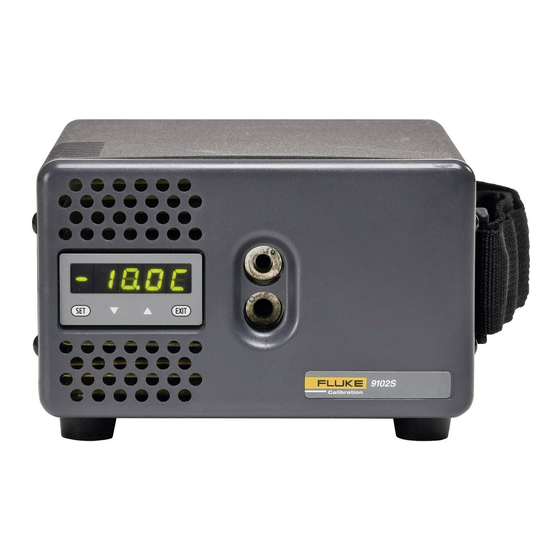
Page 12: Front Panel
9102S User’s Guide Front Panel Caution Always leave enough clearance in front of the calibrator to allow for safe and easy installation and removal of probes. Figure 3. Front Panel Strap - A strap is provided to aid the user in carrying the Product in one hand. Slide your hand into position and secure using the loop and hook fastener for a tight fit. -
Page 13: Accessories
4.8 mm (3/16 in) Insert 3102-4 6.4 mm (1/4 in) Insert 3102-5 7.9 mm (5/16 in) Insert 3102-6 9.5 mm (3/8 mm) Insert 3102-7 11.1 mm (7/16 mm) Insert 9308 Rugged Carrying Case Call your local Fluke Calibration representative for current pricing. -
Page 14: General Operation
9102S User’s Guide General Operation Set the Temperature You can enter temperature set-points from the front panel. Temperature Set-point explains how to program set-points. To set the temperature set-point on the Product using the front-panel keys: 1. Press SET twice to access the set-point value. - Page 15 Dry-well Calibrator Operation Units °C/°F Display Temperature Select Setpoint DOWN SET/EXIT Set-Point Resistance Adjust Setpoint Secondary Functions SET/EXIT EXIT Units °C/°F SET/EXIT Display Power Scan On/Off SET/EXIT SET/EXIT Set Proportuinal Band Scan Rate SET/EXIT EXIT Configuration Menu EXIT EXIT EXIT Menu Legend: Press SET to step through the menu Operating...
-
Page 16: Well Temperature
9102S User’s Guide Well Temperature The display allows direct viewing of the actual well temperature. This temperature value is normally shown on the display. The units of the temperature value (C or F) are displayed at the right. For example, Well temperature in degrees Celsius 100.0 C... -
Page 17: Set-Point Value
Dry-well Calibrator Operation Set-point Value The set-point value may be adjusted after selecting the set-point memory and pressing SET. Set-point 4 value in °C 4 50. If the set-point value does not need to be changed, press and hold EXIT to resume displaying the well temperature. -
Page 18: Scan Rate
9102S User’s Guide Scan Rate The scan rate can be set from 0.1 to 99.9 °C/min. The maximum scan rate, however, is actually limited by the natural heating or cooling rate of the Product. This rate is often <100 °C/min, especially when cooling. -
Page 19: Heater Power
Dry-well Calibrator Operation Heater Power The temperature controller controls the temperature of the well by pulsing the heater on and off. The total power being applied to the heater is determined by the duty cycle or the ratio of heater on time to the pulse cycle time. -
Page 20: Controller Configuration
9102S User’s Guide The proportional band width is easily adjusted from the front panel. The width may be set to discrete values in degrees C or F depending on the selected units. The proportional band adjustment is accessed within the secondary menu. Press SET and EXIT to enter the secondary menu and show the heater power. -
Page 21: High Limit
Dry-well Calibrator Operation High Limit The High Limit parameter adjusts the upper set-point temperature. The factory default and maximum are set to 125 °C (257 °F). The minimum setting is 50 °C (122 °F). For safety, a user can adjust the High Limit down so the maximum temperature set-point is restricted. -
Page 22: Sample Period
9102S User’s Guide Sample Period The next parameter in the serial interface parameter menu is the sample period. The sample period is the time period in seconds between temperature measurements transmitted from the serial interface. If the sample rate is set to 5, the Product transmits the current measurement over the serial interface approximately every five seconds. -
Page 23: Calibration Parameters
Dry-well Calibrator Operation Calibration Parameters The operator of the Product controller has access to a number of the calibration constants: R0, ALPHA, and DELTA. These values are set at the factory and must not be altered. The correct values are important to the accuracy and proper and safe operation of the Product. -
Page 24: Alpha
9102S User’s Guide ALPHA This probe parameter refers to the average sensitivity of the probe between 0 and 100 °C. The value of this parameter is set at the factory for best Product accuracy. Flashes for one second and then the ALPHA setting displays... -
Page 25: Rs-232 Connection
Dry-well Calibrator Digital Communication Interface RS-232 Connection The three-conductor jack for the serial port is located on the back of the Product. One serial cable is included. Additional or longer cables, of 3 m or less, can be constructed by following the wiring diagram shown in Figure 5. -
Page 26: Interface Commands
9102S User’s Guide Interface Commands Use the digital interface and commands shown in Table to access Product functions. These commands are used with the RS-232 serial interface. The commands are terminated with a carriage- return character (CR, ASCII 13). The interface makes no distinction between upper and lower case letters, so either may be used. -
Page 27: Test Probe Calibration
9.99999 0.0–3.0v Miscellaneous Other Commands Read firmware version number *ver[sion] *ver ver.9999x,9.99 ver.9102S,1.10 Read structure of all commands h[elp] list of commands Read ALL operating parameters list of parameters Read set-point 999.999 ohms 100.123 ohms Legend: [] Optional command data... -
Page 28: Calibrate A Single Probe
15 minutes to achieve maximum stability. Speeding up the calibration process can be accomplished by knowing how soon to make the measurement. Fluke Calibration recommends that typical measurements be made at the desired temperatures with the desired test probes to establish these times. -
Page 29: Calibration And Adjustment Procedure
Product temperature with higher accuracy than the accuracy of the Product. Calibration Points Fluke Calibration recommends calibrating the Product over the entire operating range at enough temperature points to evaluate Product accuracy and to be able to adjust the Product, if needed. At least three reasonably-separated temperature points are required to adjust the Product. -
Page 30: Compute Delta
9102S User’s Guide Compute DELTA − − ⎡ ⎤ ⎡ ⎤ ⎡ ⎤ ⎡ ⎤ − ⎥ − − ⎢ ⎥ ⎢ ⎢ ⎥ ⎢ ⎥ ⎣ ⎦ ⎣ ⎦ ⎣ ⎦ ⎣ ⎦ ⎡ ⎤ ⎡ ⎤ ⎡ ⎤... -
Page 31: Compute R0 And Alpha
Dry-well Calibrator Calibration and Adjustment Procedure Compute R0 and ALPHA ⎡ ⎤ ⎡ ⎤ − delta ⎢ ⎥ ⎢ ⎥ ⎣ ⎦ ⎣ ⎦ ⎡ ⎤ ⎡ ⎤ − delta ⎢ ⎥ ⎢ ⎥ ⎣ ⎦ ⎣ ⎦ rzero − alpha delta is the new value of DELTA computed above. -
Page 32: Maintenance
Contact Fluke Calibration) for more information. • Before using any cleaning or decontamination method except those recommended by Fluke Calibration, users should check with an Authorized Service Center to be sure that the proposed method will not damage the equipment. -
Page 33: Troubleshooting Problems, Possible Causes, And Solutions
Table carefully and attempt to understand and solve the problem. If the problem cannot otherwise be solved, contact an Authorized Service Center (see Contact Fluke Calibration for assistance. Be sure to have the model number, serial number, voltage, and problem description available. - Page 34 9102S User’s Guide Table 4. Troubleshooting Problem Possible Causes and Solutions Controller problem. The error messages signify problems with the controller. - a RAM error Err 1 - a NVRAM error Err 2 - a Structure error Err 3 The display shows and...
Need help?
Do you have a question about the 9102S and is the answer not in the manual?
Questions and answers