Table of Contents
Advertisement
Advertisement
Table of Contents

Related Manuals for Fluke 9103


Summary of Contents for Fluke 9103
- Page 1 9103 Dry-Well User’s Guide PN 2673813 March 2013 © 2013 Fluke Corporation. All rights reserved. Specifications are subject to change without notice. All product names are trademarks of their respective companies. Fluke-Direct .com info@Fluke-Direct.com 1.888.475.5235...
- Page 2 Fluke authorized resellers shaJI extend this warranty on new and unused producm to end�user customers only but have no authority to extend a greater or different warranty on behalf of Fluke. Warranty support is available only if product is purchased through a Fluke authorized sales outlet or Buyer has paid the applloable lntematlonal price.
-
Page 3: Table Of Contents
Set-point Value ....... . . 21 7.2.3 Temperature Scale Units ......21 Fluke-Direct .com info@Fluke-Direct.com... - Page 4 Calibration Points ......39 10.2 Calibration Procedure ......39 Fluke-Direct .com info@Fluke-Direct.com...
- Page 5 EMC Directive ....... . . 46 12.2.2 Low Voltage Directive (Safety) ......46 Fluke-Direct .com info@Fluke-Direct.com...
- Page 6 Figures Figure 1 9103 Back Panel ......14 Figure 2 9103 Front Panel ......15 Figure 3 Inserts Available for the 9103 Block Assembly .
- Page 7 International Electrical Symbols ..... 1 Table 2 9103 Controller Communications Commands ....34 Table 2 Table 2 9103 Controller Communications Commands continued .
- Page 8 Fluke-Direct .com info@Fluke-Direct.com 1.888.475.5235...
-
Page 9: Before You Start
Table 1 International Electrical Symbols Symbol Description AC (Alternating Current) AC-DC Battery CE Complies with European Union Directives Double Insulated Electric Shock Fuse PE Ground Hot Surface (Burn Hazard) Read the User’s Manual (Important Information) Fluke-Direct .com info@Fluke-Direct.com 1.888.475.5235... -
Page 10: Safety Information
9103 Dry-Well User’s Guide Symbol Description Canadian Standards Association OVERVOLTAGE (Installation) CATEGORY II, Pollution Degree 2 per IEC1010-1 re- fers to the level of Impulse Withstand Voltage protection provided. Equipment of OVERVOLTAGE CATEGORY II is energy-consuming equipment to be supplied from the fixed installation. -
Page 11: Cautions
• DO use a ground fault interrupt device. Authorized Service Centers Please contact one of the following authorized Service Centers to coordinate service on your Hart product: Fluke Corporation, Hart Scientific Division Fluke-Direct .com info@Fluke-Direct.com 1.888.475.5235... - Page 12 9103 Dry-Well User’s Guide Fluke-Direct .com info@Fluke-Direct.com 1.888.475.5235...
- Page 13 1 Before You Start Authorized Service Centers When contacting these Service Centers for support, please have the following information available: • Model Number • Serial Number • Voltage • Complete description of the problem Fluke-Direct .com info@Fluke-Direct.com 1.888.475.5235...
- Page 14 Fluke-Direct .com info@Fluke-Direct.com 1.888.475.5235...
-
Page 15: Introduction
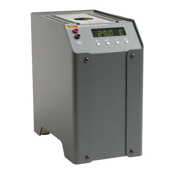
The Hart Scientific 9103 Dry-well may be used as a portable instrument or bench top temperature calibrator for calibration thermocouples and RTD tem- perature probes. The 9103 is small enough to use in the field and accurate enough to use in the lab. With an ambient temperature of 23°C (74°F), calibra- tions may be done over a range of –25°C to 140°C (–13°F to 284°F). - Page 16 Fluke-Direct .com info@Fluke-Direct.com 1.888.475.5235...
-
Page 17: Specifications And Environmental Conditions
• temperature range: 5–45°C (41–113°F) • ambient relative humidity: 15 - 50% • pressure: 75kPa - 106kPa • mains voltage within ± 10% of nominal • vibrations in the calibration environment should be minimized • altitude less than 2,000 meters Fluke-Direct .com info@Fluke-Direct.com 1.888.475.5235... -
Page 18: Warranty
Fluke-Direct .com info@Fluke-Direct.com 1.888.475.5235... -
Page 19: Quick Start
Unpack the instrument carefully and inspect it for any damage that may have occurred during shipment. If there is shipping damage, notify the carrier immediately. Verify that the following components are present: • 9103 Dry-well • Insert for configuration ordered • Power Cord • Insert Removal Tongs •... -
Page 20: Setting The Temperature
9103 Dry-Well User’s Guide Setting the Temperature Section 7.2 explains in detail how to set the temperature set-point on the cali- brator using the front panel keys. The procedure is summarized here. (1) Press “SET” twice to access the set-point value. -
Page 21: Parts And Controls
SET – Used to display the next parameter in the menu and to store parameters to the displayed value. DOWN – Used to decrement the displayed value or parameter. UP – Used to increment the displayed value or parameter. Fluke-Direct .com info@Fluke-Direct.com 1.888.475.5235... -
Page 22: Figure 1 9103 Back Panel
9103 Dry-Well User’s Guide RS-232 FLUKE CORPORATION HART SCIENTIFIC DIVISION www.hartscientific.com POWER 93–234 VAC 3 A 50/60 Hz 250 V Figure 1 9103 Back Panel Fluke-Direct .com info@Fluke-Direct.com 1.888.475.5235... -
Page 23: Constant Temperature Block Assembly
DOWN EXIT HOLD Figure 2 9103 Front Panel EXIT – Used to exit a function and to skip to the next function. Any changes made to the displayed value are ignored. Holding “EXIT” for about ½ a second returns control to the main display. -
Page 24: Figure 3 Inserts Available For The 9103 Block Assembly
Insert “D” 1/4" 1/16" 1/4" 1/4" 4 mm 3/16" 3 mm 3/8" 1/2" 3/8" 3/8" 6 mm 6 mm 3/16" 3 mm 4 mm 3/16" 1/4" 1/8" Figure 3 Inserts Available for the 9103 Block Assembly Fluke-Direct .com info@Fluke-Direct.com 1.888.475.5235... -
Page 25: General
The power of the instrument is precisely controlled by the temperature control- ler to maintain a constant temperature. Power is controlled by periodically switching the TEDs on for a certain amount of time using power transistors. Fluke-Direct .com info@Fluke-Direct.com 1.888.475.5235... - Page 26 Fluke-Direct .com info@Fluke-Direct.com 1.888.475.5235...
-
Page 27: Controller Operation
To set the temperature, first select the set-point memory. This function is ac- cessed from the temperature display function by pressing “SET”. The number of the set-point memory currently being used is shown at the left on the display followed by the current set-point value. Fluke-Direct .com info@Fluke-Direct.com 1.888.475.5235... -
Page 28: Figure 4 Controller Operation Flowchart
9103 Dry-Well User’s Guide Display Hold Temperature Display Temperature DOWN DOWN Select Setpoint Displays Set-Point Resistance Adjust Setpoint EXIT Toggles °C / °F EXIT Units °C/°F Secondary Functions EXIT Scan On/Off Menu EXIT Display Power Scan Rate Set Proportional Band Adj. -
Page 29: Set-Point Value
Celsius (°C) or Fahrenheit (°F). The units are used in displaying the well tem- perature, set-point, and proportional band. Press “SET” after adjusting the set-point value to change display units. Un= C Scale units currently selected Press “UP” or “DOWN” to change the units. New units selected Un= F Fluke-Direct .com info@Fluke-Direct.com 1.888.475.5235... -
Page 30: Scan
9103 Dry-Well User’s Guide Scan The scan rate can be set and enabled so that when the set-point is changed the calibrator heats or cools at a specified rate (degrees per minute) until it reaches the new set-point. With the scan disabled the calibrator heats or cools at the maximum possible rate. -
Page 31: Enabling The Hold Temperature Display
Internally the black terminal connects to ground. The red terminal connects to +5V through a 100 kΩ resistor. The cali- brator measures the voltage at the red terminal and interprets +5V as open and 0V as closed. Fluke-Direct .com info@Fluke-Direct.com 1.888.475.5235... -
Page 32: Switch Test Example
9103 Dry-Well User’s Guide 7.4.4 Switch Test Example This section describes a possible application for the switch hold temperature display feature and how the instrument is set up and operated. Suppose you have a thermal switch which is supposed to open at about 75°C and close at about 50°C and you want to test the switch to see how accurate and... -
Page 33: Thermal Electric Devices (Ted)
If the proportional band is too narrow the temperature may swing back and forth because the controller overreacts to temperature variations. For best con- trol stability the proportional band must be set for the optimum width. Fluke-Direct .com info@Fluke-Direct.com 1.888.475.5235... -
Page 34: Controller Configuration
9103 Dry-Well User’s Guide The proportional band width is set at the factory to about 15.0°C. The propor- tional band width may be altered by the user if he desires to optimize the con- trol characteristics for a particular application. -
Page 35: Serial Interface Parameters
The BAUD rate of the serial communications may be programmed to 300 600, 1200, 2400, 4800, or 9600 BAUD. 2400 BAUD is the default setting. Use “UP” or “DOWN” to change the BAUD rate value. New BAUD rate 4800 b Fluke-Direct .com info@Fluke-Direct.com 1.888.475.5235... -
Page 36: Sample Period
9103 Dry-Well User’s Guide Press “SET” to set the BAUD rate to the new value or “EXIT” to abort the op- eration and skip to the next parameter in the menu. 7.12.2 Sample Period The sample period is the next parameter in the serial interface parameter menu. -
Page 37: Calibration Parameters
7.13.2 ALPHA This probe parameter refers to the average sensitivity of the probe between 0 and 100°C. The value of this parameter is set at the factory for best instrument accuracy. Fluke-Direct .com info@Fluke-Direct.com 1.888.475.5235... -
Page 38: Delta
9103 Dry-Well User’s Guide 7.13.3 DELTA This probe parameter characterizes the curvature of the resistance-temperature relationship of the sensor. The value of this parameter is set at the factory for best instrument accuracy. 7.13.4 BETA This probe parameter characterizes the low temperatures. The value of this pa- rameter is set at the factory for best instrument accuracy. -
Page 39: Figure 5 Serial Cable Wiring
METER in length. 8.1.2 Setup Before operation the serial interface must first be set up by programming the BAUD rate and other con- figuration parameters. These parameters are pro- Figure 5 Serial Cable Wiring grammed within the serial Fluke-Direct .com info@Fluke-Direct.com 1.888.475.5235... -
Page 40: Baud Rate
BAUD rate parameter by showing “bAUd”. Press “SET” to choose to set the BAUD rate. The current BAUD rate is displayed. The BAUD rate of the 9103 serial communications may be programmed to 300, 600, 1200, 2400, 4800, or 9600 baud. The BAUD rate is pre-programmed to 2400 BAUD. Use “UP”... -
Page 41: Serial Operation
Characters are shown in lower case although upper case may be used. Spaces may be added within command strings and will simply be ignored. Backspace (BS, ASCII 8) may be used to erase the previous character. A termi- nating CR is implied with all commands. Fluke-Direct .com info@Fluke-Direct.com 1.888.475.5235... -
Page 42: Table 2 9103 Controller Communications Commands
9103 Dry-Well User’s Guide Table 2 9103 Controller Communications Commands Command Command Returned Acceptable Command Description Format Example Returned Example Values Display Temperature Read current set-point s[etpoint] set: 999.9 {C or F} set: 100.00 C Set current set-point to n s[etpoint]=n s=200.0... - Page 43 8 Digital Communication Interface Interface Commands Table 2 9103 Controller Communications Commands continued Command Command Returned Acceptable Command Description Format Example Returned Example Values Read R0 calibration parameter r[0] r0: 999.999 r0: 100.578 Set R0 calibration parameter to n r[0]=n r=100.324...
- Page 44 Fluke-Direct .com info@Fluke-Direct.com 1.888.475.5235...
-
Page 45: Test Probe Calibration
Speeding up the calibration process can be accomplished by knowing how soon to make the measurement. Typical measurements should be made at the desired temperatures with the desired test probes to establish these times. Fluke-Direct .com info@Fluke-Direct.com 1.888.475.5235... - Page 46 Fluke-Direct .com info@Fluke-Direct.com 1.888.475.5235...
-
Page 47: Compute Delta
3. Repeat step 2 for the other three set-points recording them as T and R respectively. 4. Using the recorded data, calculate new values for R0, ALPHA, DELTA, and BETA parameters using the equations given below. 10.2.1 Compute DELTA − Fluke-Direct .com info@Fluke-Direct.com 1.888.475.5235... -
Page 48: Compute R0 And Alpha
− − delta − DE CF - Measured temperature using thermometer. - Value of R from display of 9103 (Press SET and DOWN at the same time.) where and R are the measured temperature and resistance at –25°C and R are the measured temperature and resistance at 0°C... -
Page 49: Compute Beta
Repeat step 2 for ALPHA and DELTA. 10.2.4 Accuracy and Repeatability Check the accuracy of the instrument at various points over the calibrated range. If the instrument does not pass specification at all set-points, repeat the Calibration Procedure. Fluke-Direct .com info@Fluke-Direct.com 1.888.475.5235... - Page 50 Fluke-Direct .com info@Fluke-Direct.com 1.888.475.5235...
-
Page 51: Maintenance
• If the instrument is used in a manner not in accordance with the equip- ment design, the operation of the calibrator may be impaired or safety hazards may arise. Fluke-Direct .com info@Fluke-Direct.com 1.888.475.5235... - Page 52 Fluke-Direct .com info@Fluke-Direct.com 1.888.475.5235...
-
Page 53: Trouble Shooting
2, err 3, err 4, or err 5 Err 3 - a Structure error Err 4 - an ADC setup error Err 5 - an ADC ready error Initialize the system by performing the Factory Reset Sequence describe above. Fluke-Direct .com info@Fluke-Direct.com 1.888.475.5235... -
Page 54: Ce Comments
9103 Dry-Well User’s Guide Problem Possible Causes and Solutions The display shows Defective control sensor. The control sensor may be shorted, open or otherwise err 6 and damaged. Perform the Factory Reset Sequence described above. If this does not fix flashes SenSor the problem, contact a Hart Scientific Authorized Service Center.
Need help?
Do you have a question about the 9103 and is the answer not in the manual?
Questions and answers