
Related Manuals for Siemens SIMATIC NET RUGGEDCOM RX1400


Summary of Contents for Siemens SIMATIC NET RUGGEDCOM RX1400
- Page 1 Installation Manual SIMATIC NET Rugged Multi Service Platforms RUGGEDCOM RX1400 Edition 01/2021 https://www.siemens.com...
- Page 2 Preface Introduction Installing the Device SIMATIC NET Device Management Rugged Multi Service Platforms RUGGEDCOM RX1400 Communication Ports Technical Specifications Installation Manual Certification 01/2021 C79000-G8976-1103-17...
- Page 3 Note the following: WARNING Siemens products may only be used for the applications described in the catalog and in the relevant technical documentation. If products and components from other manufacturers are used, these must be recommended or approved by Siemens. Proper transport, storage, installation, assembly, commissioning, operation and maintenance are required to ensure that the products operate safely and without any problems.
-
Page 4: Table Of Contents
Related Documents ......................... v Registered Trademarks ......................v Warranty ..........................v Training ..........................vi Customer Support ........................vi Contacting Siemens ....................... vii Introduction ........................... 1 Feature Highlights ....................1 Description ......................2 Article Number ...................... 4 Required Tools and Materials ................. 6 Decommissioning and Disposal ................ - Page 5 Table of Contents Configuring the Device ..................30 Installing the SIM Cards ..................30 Inserting/Removing the MicroSD Card ..............31 Communication Ports ......................33 Fast Ethernet Ports ....................33 SFP Transceivers ....................34 Serial Ports ......................35 Technical Specifications ...................... 39 Power Supply Specifications ................
-
Page 6: Preface
Warranty Siemens warrants this product for a period of five (5) years from the date of purchase, conditional upon the return to factory for maintenance during the warranty term. This product contains no user-serviceable parts. Attempted service by unauthorized personnel shall render all warranties null and void. -
Page 7: Training
Siemens Sales representative. Customer Support Customer support is available 24 hours, 7 days a week for all Siemens customers. For technical support or general information, contact Siemens Customer Support through any of the following methods: Online Visit http://www.siemens.com/automation/support-request... -
Page 8: Contacting Siemens
Preface Contacting Siemens • Contact a local Siemens representative from Sales, Technical Support, Training, etc. • Ask questions or share knowledge with fellow Siemens customers and the support community Contacting Siemens Address Siemens AG Industry Sector 300 Applewood Crescent Concord, Ontario... - Page 9 Preface Contacting Siemens viii RUGGEDCOM RX1400 Installation Manual, 01/2021, C79000-G8976-1103-17...
-
Page 10: Introduction
Introduction The RUGGEDCOM RX1400 is a multi-protocol intelligent node that combines Ethernet switch, routing and firewall functionality with various wide area connectivity options. The RUGGEDCOM RX1400 switch, with its rugged metal housing, is designed for DIN rail, panel or rack mounting. The RUGGEDCOM RX1400 provides a high level of immunity to electromagnetic interference, heavy electrical surges, extreme temperature and humidity for reliable operation in harsh environments. -
Page 11: Description
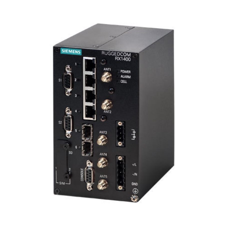
Introduction 1.2 Description Power Supply Other Interfaces • 12 to 24 VDC • Isolated built-in power input • ±12 to 24 VDC • RS-232 console port for local management/diagnostics on the • ±48 VDC device • HI VAC/VDC • SMA connectors for cellular, GPS Ethernet Interfaces and RF interfaces •... - Page 12 Introduction 1.2 Description Power Supply Terminal Block RS232 Serial Console Port (DB9) ANT5 Port POWER LED ALARM LED CELL LED Figure 1.1 RUGGEDCOM RX1400 Product Label The product label details the product name, barcode, standards compliance, etc. It also defines the article number, which describes the hardware configuration.
-
Page 13: Article Number
Introduction 1.3 Article Number Article Number The article number defines the device's hardware configuration. It is generated from the options selected in the RUGGEDCOM Selector at the time of ordering and printed on the product label affixed to the device. Power Module Mounting Kit Manufacturing Modification LTE Radio... - Page 14 Introduction 1.3 Article Number LTE Radio Options Option Description None LTE Europe LTE NAM ATT/RGRS/TLS/BLL LTE NAM Verizon LTE APAC LTE Global LTE NAM ATT/VZW/RGRS/TLS/BLL WLAN Modem Options Option Description None WLAN Modem US WLAN Modem Non-US SFP Transceiver (Port 5) Options Option Description None...
-
Page 15: Required Tools And Materials
RUGGEDCOM CROSSBOW ADM for VPE1400 Required Tools and Materials The following tools and materials are required to install the RUGGEDCOM RX1400: Tool/Material Available For Purchase From Siemens WLAN, LTE and/or GPS antennas ü Antenna N-connect and/or SMA cables ü AC/DC power cord (16 AWG) û... -
Page 16: Decommissioning And Disposal
Siemens also does not recommend using copper Ethernet ports to interface with devices in the field across distances that could produce high levels of ground potential rise (i.e. greater than 2500 V), during line-to-ground fault conditions. -
Page 17: Gigabit Ethernet 1000Base-Tx Cabling Recommendations
Introduction 1.6.2 Gigabit Ethernet 1000Base-TX Cabling Recommendations 1.6.2 Gigabit Ethernet 1000Base-TX Cabling Recommendations The IEEE 802.3ab Gigabit Ethernet standard defines 1000 Mbit/s Ethernet communications over distances of up to 100 m (328 ft) using all 4 pairs in category 5 (or higher) balanced, unshielded twisted-pair cabling. For wiring guidelines, system designers and integrators should refer to the Telecommunications Industry Association (TIA) TIA/EIA-568-A wiring standard that characterizes minimum cabling performance specifications required for proper Gigabit Ethernet operation. -
Page 18: Installing The Device
This product contains no user-serviceable parts. Attempted service by unauthorized personnel shall render all warranties null and void. Changes or modifications not expressly approved by Siemens AG could invalidate specifications, test results, and agency approvals, and void the user's authority to operate the equipment. -
Page 19: General Procedure
Inspect the package for damage before opening it. Visually inspect each item in the package for any physical damage. Verify all items are included. IMPORTANT If any item is missing or damaged, contact Siemens for assistance. RUGGEDCOM RX1400 Installation Manual, 01/2021, C79000-G8976-1103-17... -
Page 20: Installing The Device In Hazardous Locations
Installing the Device 2.3 Installing the Device in Hazardous Locations Installing the Device in Hazardous Locations The RUGGEDCOM RX1400 is designed to comply with the safety standards for Class I, Division 2, Zone 2 hazardous locations where concentrations of flammable gases, vapors or liquids may be present, as opposed to normal operating environments. -
Page 21: Mounting The Device
Installing the Device 2.4 Mounting the Device Mounting the Device The RUGGEDCOM RX1400 is designed for maximum mounting and display flexibility. It can be equipped with brackets that allow it to be installed in a rack, on a DIN rail, or directly on a panel. Note Heat generated by the device is channeled outwards from the enclosure. - Page 22 Installing the Device 2.4.1 Mounting the Device on a DIN Rail Mounting the Device To mount the device to a DIN rail, do the following: Hook the top teeth of the adapter onto the DIN rail. Note The adapter features a sliding release with a slot at the bottom for a flathead screwdriver.
-
Page 23: Mounting The Device To A Panel
Installing the Device 2.4.2 Mounting the Device to a Panel Removing the Device To remove the device from a DIN rail, do the following: Insert a flathead screwdriver into the slot of the sliding release and move it down. DIN Rail DIN Rail Adapter Figure 2.3 Removing the Device from a DIN Rail... -
Page 24: Mounting The Device To A Rack
Installing the Device 2.4.3 Mounting the Device to a Rack To mount the device to a panel, do the following: Place the device against the panel and align the adapters with the mounting holes. Screw Panel Adapter Figure 2.4 Panel Mounting Install the supplied screws to secure the adapters to the panel. 2.4.3 Mounting the Device to a Rack For rack mount installations, the RUGGEDCOM RX1400 can be equipped with rack... -
Page 25: Connecting The Antennas
Installing the Device 2.5 Connecting the Antennas • Do not overload the supply circuit. Refer to the over-current protection and power supply ratings specified by the rack manufacturer. • Make sure the rack and all devices have a proper ground-to-Earth connection. Pay particular attention to power supply connections other than direct connections to the branch circuit (e.g. -
Page 26: Antenna Ports
The RUGGEDCOM RX1400 supports the following antennas. Cellular, GPS and WLAN Antennas Antenna Type Operating Gain (dBi) Article Number Reference Frequency (GHz) ANT1995-4MM Omni- 6GK6000-8NS01-1AA0 https:// Directional support.industry.siemens.com/ cs/ww/en/view/109748485 0.7 to 1.0 3.0 to 4.0 1.7 to 2.7 RUGGEDCOM RX1400 Installation Manual, 01/2021, C79000-G8976-1103-17... - Page 27 2.5.2 Available Antennas Cellular and GPS Antennas Antenna Type Operating Gain (dBi) Article Number Reference Frequency (GHz) ANT1096-4ME Omni- 6GK6000-8NT01-1AA0 https:// Directional support.industry.siemens.com/ cs/ww/en/view/109477766 ANT1096-4MA Omni- 6GK6000-8NT01-0AA0 https:// Directional support.industry.siemens.com/ cs/me/en/view/109477585 GPS Antennas Antenna Type Operating Gain (dBi) Article Number Reference...
-
Page 28: Connecting Lte Antennas
Installing the Device 2.5.3 Connecting LTE Antennas Antenna Type Operating Gain (dBi) Article Number Reference Frequency (GHz) ANT795-4MA Omni- 6GK5795-4MA00-0AA0 https:// Directional support.industry.siemens.com/ cs/ww/en/view/61199227 ANT795-4MC Omni- 6GK5795-4MC00-0AA0 https:// Directional support.industry.siemens.com/ cs/ww/en/view/61199227 ANT795-4MD Omni- 6GK5795-4MD00-0AA0 https:// Directional support.industry.siemens.com/ cs/ww/en/view/61199227 ANT795-4MX Omni- 6GK5795-4MX00-0AA0... - Page 29 Tested in accordance with UL 50 and UL 497 Note A Radio Frequency (RF) site survey is recommended prior to any installation to help determine the best location for the LTE antennas. For assistance, contact a Siemens Sales representative. Note The cellular modem supports SISO (Single Input Single Output) and MIMO (Multiple Input Multiple Output) modes.
-
Page 30: Connecting A Gps Antenna
Installing the Device 2.5.4 Connecting a GPS Antenna Note For technical specifications, refer to "Cellular Modem Specifications (Page 40)". Note A specific brand of antenna is not specified. Mount the antenna to a pole or wall in an area that provides good signal coverage and is away from any signal noise emanating from other communications equipment. - Page 31 Note A site survey is recommended prior to any installation to help determine the best location for the GPS antenna. For assistance, contact a Siemens Sales representative. Note Although it is impossible to protect the antenna from a direct lightning strike, the antenna and connected components can be protected from secondary effects through site selection and by installing protection devices.
-
Page 32: Connecting Wlan Antennas
Installing the Device 2.5.5 Connecting WLAN Antennas If required, connect the optional lightning arrestor, line amplifier or bandpass filter to the antenna. RUGGEDCOM RX1400 Shielded Coaxial Cable Lightning Protector, Line Amplifier or Bandpass Filter GPS Antenna Figure 2.8 Antenna and Lightning Protector Assembly (Optional) Using shielded coaxial cables, connect the antenna assembly to the ANT2 port on the device. -
Page 33: Connecting The Failsafe Alarm Relay
Installing the Device 2.6 Connecting the Failsafe Alarm Relay Using shielded coaxial cables, connect the antenna to either the ANT3 (SISO) or ANT4 (MIMO) port on the device. Make sure the cable is routed away from any noise sources, such as Switch-Mode Power Supplies (SMPS). If needed, install a lightning protect between the antenna and the device. -
Page 34: Connecting Power
Installing the Device 2.7 Connecting Power Normally Open Figure 2.10 Failsafe Alarm Relay Wiring Connecting Power The RUGGEDCOM RX1400 supports a single integrated high AC/DC or low DC power supply. Note Before installing the device, note the following: • An appropriately rated AC or DC circuit breaker must be installed. •... - Page 35 Installing the Device 2.7.1 Connecting High AC/DC Power Connect the power supply terminal block to the device. Surge Ground Terminal Negative/Neutral (-/N) Terminal Positive/Live (+/L) Terminal Braided Ground Cable Power Supply Terminal Block Figure 2.11 Terminal Block Wiring Connect the positive wire from the power source to the positive/live (+/L) terminal on the terminal block.
-
Page 36: Connecting Low Dc Power
Installing the Device 2.7.2 Connecting Low DC Power 2.7.2 Connecting Low DC Power To connect a low DC power supply to the device, do the following: Connect the power supply terminal block to the device. Surge Ground Terminal Negative Terminal Positive Terminal Braided Ground Cable Power Supply Terminal Block Figure 2.12... - Page 37 Installing the Device 2.7.2 Connecting Low DC Power RUGGEDCOM RX1400 Installation Manual, 01/2021, C79000-G8976-1103-17...
-
Page 38: Device Management
Device Management This section describes how to connect to and manage the device. Connecting to the Device The following describes the various methods for accessing the RUGGEDCOM RX1400 console and Web interfaces on the device. For more detailed instructions, refer to the RUGGEDCOM ROX-II Configuration Manual for the RUGGEDCOM RX1400. -
Page 39: Configuring The Device
Device Management 3.2 Configuring the Device Name Reserved (Do Not Connect) Reserved (Do Not Connect) For information about how to connect to the device via the serial console port, refer to the RUGGEDCOM ROX-II CLI Configuration Manual for the RUGGEDCOM RX1400. Communication Ports Connect any of the available Ethernet ports on the device to a management switch and access the RUGGEDCOM RX1400 console and Web interfaces via the... -
Page 40: Inserting/Removing The Microsd Card
Device Management 3.4 Inserting/Removing the MicroSD Card Remove the SIM card access panel. Access Panel Secondary Micro-SIM Card Primary Micro-SIM Card Figure 3.2 Accessing the SIM Cards Insert the SIM cards into the slots. Slot 1 is for the primary SIM card and slot 2 is for the secondary (backup) SIM card. - Page 41 Device Management 3.4 Inserting/Removing the MicroSD Card NOTICE Security hazard – risk of unauthorized access and/or exploitation Make sure to remove the microSD card before decommissioning the device or sending the device to a third-party. To insert or remove a microSD card, do the following: Power down the device.
-
Page 42: Communication Ports
Communication Ports The RUGGEDCOM RX1400 can be equipped with various types of communication ports to enhance its abilities and performance. Serial Ports Access Plate ANT1 Port Fast Ethernet Ports ANT2 Port SFP Transceiver Ports ANT3 Port ANT4 Port ANT5 Port Figure 4.1 Port Assignment Note... -
Page 43: Sfp Transceivers
Reserved (Do Not Connect) SFP Transceivers The RUGGEDCOM RX1400 features two Small Form-Factor Pluggable (SFP) transceiver sockets, which are compatible with a wide array of SFP transceivers available from Siemens. LEDs Each socket features an LED that indicates its link state. State... -
Page 44: Serial Ports
RUGGEDCOM SFP Transceiver Catalog [https:// support.industry.siemens.com/cs/ca/en/view/109482309]. Note Only use SFP transceivers approved by Siemens for RUGGEDCOM products. Siemens accepts no liability as a result of performance issues related in whole or in part to third-party components. SFP Transceiver... - Page 45 Communication Ports 4.3 Serial Ports Serial DB9 Port Figure 4.3 Serial DB9 Port Pin Configuration Mode RS-232 RS-422 RS-485 Reserved (Do Not Connect) RX-/TX- Reserved (Do Not Connect) Common (Isolated) Ground Reserved (Do Not Connect) RX+/TX+ Reserved (Do Not Connect) Shield Chassis Ground In RS-232 mode, ports are wired as DTE (Data Terminal Equipment).
- Page 46 Communication Ports 4.3 Serial Ports 120Ω 10nF 120Ω 10nF RUGGEDCOM RX1400 Device Common (Isolated Ground) Negative Positive Shield to Earth (Connected At a Single Point) RS-485 Devices (32 Total) Figure 4.4 Recommended RS-485 Wiring RUGGEDCOM RX1400 Installation Manual, 01/2021, C79000-G8976-1103-17...
- Page 47 Communication Ports 4.3 Serial Ports RUGGEDCOM RX1400 Installation Manual, 01/2021, C79000-G8976-1103-17...
-
Page 48: Technical Specifications
Technical Specifications This chapter provides important technical specifications related to the device. Power Supply Specifications The RUGGEDCOM RX1400 includes one of the following internal power supplies: Maximum Power Power Supply Type Input Range Internal Fuse Rating Consumption 88-264 VAC 98-300 VDC 3.15 A(T) ±48V VDC ±36-72 VDC... -
Page 49: Serial Port Specifications
Technical Specifications 5.4 Serial Port Specifications Wiring Standard TIA/EIA T568A/B Maximum Distance 100 m (328 ft) Isolation 1.5 kV Auto-negotiating. Shielded or unshielded. Auto-crossover and auto-polarity. RMS 1 minute. Serial Port Specifications The RUGGEDCOM RX1400 supports two serial ports with female DB9 connectors. For more information about the serial ports, refer to "Serial Ports (Page 35)". - Page 50 Technical Specifications 5.5.1 LTE Specifications Band Modem Option Frequency Transmit (Tx) Receive (Rx) 1900 1850-1910 1930-1990 Ÿ Ÿ Ÿ Ÿ 1800 1710-1785 1805-1880 Ÿ Ÿ Ÿ 1700 1710-1755 2110-2155 Ÿ Ÿ Ÿ Ÿ ...
-
Page 51: Gnss Specifications
Technical Specifications 5.5.2 GNSS Specifications Supported LTE Bandwidths Band Network 1.4 MHz 3 MHz 5 MHz 10 MHz 15 MHz 20 MHz Europe Ÿ Ÿ Ÿ Ÿ AT&T Ÿ Ÿ Ÿ Ÿ Ÿ Ÿ Europe Ÿ Ÿ Ÿ Ÿ Ÿ... -
Page 52: Wlan Specifications
Technical Specifications 5.6 WLAN Specifications Gain • Maximum gain and uniform coverage in the high elevation angle and zenith • Gain in azimuth plane is not desired Average 3D gain > -5 dBi Isolation between GNSS and > 10 dB in all uplink bands LTE Main (Primary) Typical VSWR <... -
Page 53: Mechanical Specifications
Technical Specifications 5.8 Mechanical Specifications Mechanical Specifications Weight 2.5 kg (5.5 lb) Ingress Protection IP30 Enclosure Aluminum Dimension Drawings Note All dimensions are in millimeters, unless otherwise stated. 88.0 120.0 130.1 Figure 5.1 Overall Dimensions RUGGEDCOM RX1400 Installation Manual, 01/2021, C79000-G8976-1103-17... - Page 54 Technical Specifications 5.9 Dimension Drawings 465.2 3 x 45° 482.0 418.0 Figure 5.2 Rack Mount Dimensions RUGGEDCOM RX1400 Installation Manual, 01/2021, C79000-G8976-1103-17...
- Page 55 Technical Specifications 5.9 Dimension Drawings 142.1 Figure 5.3 Panel Mount Dimensions RUGGEDCOM RX1400 Installation Manual, 01/2021, C79000-G8976-1103-17...
- Page 56 Technical Specifications 5.9 Dimension Drawings 129.6 139.7 Figure 5.4 Din Rail Mount Dimensions RUGGEDCOM RX1400 Installation Manual, 01/2021, C79000-G8976-1103-17...
- Page 57 Technical Specifications 5.9 Dimension Drawings RUGGEDCOM RX1400 Installation Manual, 01/2021, C79000-G8976-1103-17...
-
Page 58: Certification
Certification The RUGGEDCOM RX1400 device has been thoroughly tested to guarantee its conformance with recognized standards and has received approval from recognized regulatory agencies. Approvals This section details the standards to which the RUGGEDCOM RX1400 complies. 6.1.1 This device meets the requirements of the following Canadian Standards Association (CSA) standards under certificate 16.70029035: •... -
Page 59: Csa/Sira
• Ex nA nC IIC T4 Gc • Class I, Zone 2, AEx nA nC IIC T4 Gc A copy of the CSA Certificate of Compliance is available via Siemens Industry Online Support at https://support.industry.siemens.com/cs/ww/en/view/109744578. 6.1.2 CSA/Sira This device meets the requirements of the following CSA/Sira standards and is approved for use in hazardous locations under certificates Sira 15ATEX4323X and IECEx CSA 16.0004X:... -
Page 60: Tüv Süd
National standard, with UL 62368-1) • UL 62368-1 Information Technology Equipment – Safety – Part 1: General Requirements A copy of the TUV Certificate is available via Siemens Industry Online Support at https://support.industry.siemens.com/cs/ww/en/view/109476631. 6.1.4 European Union (EU) This device is declared by Siemens AG to comply with essential requirements and other relevant provisions of the following EU directives: •... - Page 61 The device is marked with a CE marking and notified body number, and can be used throughout the European community. 0682 A copy of the EU Declaration of Conformity is available via Siemens Industry Online Support at https://support.industry.siemens.com/cs/ww/en/view/109475609. Notices specific to the European Union:...
-
Page 62: Fcc
Connect the device into an outlet on a circuit different from that to which the receiver is connected • Contact Siemens Customer Support for assistance Notes specific to the FCC: Note Changes or modifications not expressly approved by the party responsible for compliance could void the user's authority to operate this device. -
Page 63: Fda/Cdrh
Title 21 Code of Federal Regulations (CFR) – Chapter I – Sub-chapter J – Radiological Health 6.1.7 ISED This device is declared by Siemens AG to meet the requirements of the following ISED (Innovation Science and Economic Development Canada) standard: • CAN ICES-3 (B)/NMB-3 (B) - Page 64 Certification 6.1.7 ISED Note Conformément à la réglementation d'Industrie Canada, cet émetteur radio ne peut fonctionner à l'aide d'une antenne d'un type et maximum (ou moins) Gain approuvé pour l'émetteur par Industrie Canada. Pour réduire le risque d'interférence avec d'autres utilisateurs, le type d'antenne et son gain doivent être choisis afin que la Puissance Isotrope Rayonnée Équivalente (PIRE) ne dépasse pas ce qui est nécessaire pour une communication réussie.
- Page 65 Certification 6.1.7 ISED Note Le gain maximal d'antenne permis (pour les dispositifs utilisant la bande 5725-5825 MHz) doit se conformer à la limite de PIRE spécifiée pour l'exploitation point à point et non point à point, selon le cas. Les utilisateurs êtes avisés que les utilisateurs de radars de haute puissance sont désignés utilisateurs principaux (c.-à-d., qu'ils ont la priorité) pour les bandes 5250-5 350 MHz et 5650-5850 MHz et que ces radars pourraient causer du brouillage et/ou des dommages aux dispositifs LAN-EL.
-
Page 66: Iso
Certification 6.1.8 ISO Antenna Article Number ANT792-4DN 6GK5792-4DN00-0AA6 ANT792-6MN 6GK5792-6MN00-0AA6 ANT792-8DN 6GK5792-8DN00-0AA6 ANT793-4MN 6GK5792-8DN00-0AA6 ANT793-6MN 6GK5793-6MN00-0AA6 ANT795-4MA 6GK5795-4MA00-0AA0 ANT795-4MC 6GK5795-4MC00-0AA0 ANT795-4MD 6GK5795-4MD00-0AA0 ANT795-4MX 6GK5795-4MX00-0AA0 ANT795-6DC 6GK5795-6DC00-0AA0 ANT795-6MN 6GK5795-6MN10-0AA6 ANT795-6MT 6GK5795-6MT00-0AA0 For more information about each approved antenna, refer to "Available Antennas (Page 17)". -
Page 67: Anatel
Certification 6.1.10 ANATEL A copy of the KC Declaration of Conformity is available from Siemens AG. For contact information, refer to "Contacting Siemens (Page vii)". Notices specific to the RRA: WARNING Class B Equipment (Industrial Broadcasting and Communication Equipment) This device complies with the limits of a Class B electromagnetic wave device and is intended for use outside of a residential environment. -
Page 68: Acma
A copy of the Declaration of Conformity is available via Siemens Industry Online Support at https://support.industry.siemens.com/cs/ww/en/view/109747499. 6.1.13 RoHS This device is declared by Siemens AG to meet the requirements of the following RoHS (Restriction of Hazardous Substances) directives for the restricted use of certain hazardous substances in electrical and electronic equipment: •... -
Page 69: Emc And Environmental Type Tests
Certification 6.2 EMC and Environmental Type Tests • IEC 61000-6-2 Electromagnetic Compatibility (EMC) – Part 6-2: Generic Standards – Immunity for Industrial Environments • NEMA TS-2 Traffic Controller Assemblies with NTCIP Requirements EMC and Environmental Type Tests The RUGGEDCOM RX1400 has passed the following Electromagnetic Compatibility (EMC) and environmental tests. - Page 70 AC Power Ports HV Impulse Signal Ports 5 kV DC Power Ports Siemens-specified severity levels EMC Immunity Type Tests per IEEE 1613 Note The RUGGEDCOM RX1400 meets Class 1 requirements for copper ports, which allows for temporary communication loss. Test...
- Page 71 Certification 6.2 EMC and Environmental Type Tests Test Description Test Levels IEC 60068-2-30 Humidity (Damp Heat, Cyclic) Test Db 95% (Non-Condensing), 55 °C (131 °F), 6 cycles IEC 60068-78 Humidity (Damp Heat, Steady State) 10 days @ 55 °C (131 °F) and 93% Relative Humidity IEC 60255-21-1 Vibration...
- Page 72 Further Information Siemens RUGGEDCOM https://www.siemens.com/ruggedcom Industry Online Support (service and support) https://support.industry.siemens.com Industry Mall https://mall.industry.siemens.com Siemens AG Digital Industry Process Automation Postfach 48 48 90026 NÜRNBERG GERMANY...
Need help?
Do you have a question about the SIMATIC NET RUGGEDCOM RX1400 and is the answer not in the manual?
Questions and answers