
Related Manuals for Siemens SIMATIC NET RUGGEDCOM RS920W


Summary of Contents for Siemens SIMATIC NET RUGGEDCOM RS920W
- Page 1 Installation Manual SIMATIC NET Rugged Ethernet Switches RUGGEDCOM RS920W Edition 04/2021 https://www.siemens.com...
- Page 2 Preface Introduction Installing the Device SIMATIC NET Device Management Rugged Ethernet Switches RUGGEDCOM RS920W Communication Ports Technical Specifications Installation Manual Certification 04/2021 C79000-G8976-1033-09...
- Page 3 Note the following: WARNING Siemens products may only be used for the applications described in the catalog and in the relevant technical documentation. If products and components from other manufacturers are used, these must be recommended or approved by Siemens. Proper transport, storage, installation, assembly, commissioning, operation and maintenance are required to ensure that the products operate safely and without any problems.
-
Page 4: Table Of Contents
Accessing Documentation ....................... v Registered Trademarks ......................v Warranty ..........................v Training ..........................vi Customer Support ........................vi Contacting Siemens ....................... vii Introduction ........................... 1 Feature Highlights ....................2 Description ......................2 Required Tools and Materials ................. 4 Decommissioning and Disposal ................4 Cabling Recommendations .................. - Page 5 Table of Contents Technical Specifications ...................... 25 Power Supply Specifications ................25 Failsafe Alarm Relay Specifications ..............26 Supported Networking Standards ................ 26 Serial Port Specifications ..................26 Operating Environment ..................27 Mechanical Specifications ..................27 Dimension Drawings ................... 27 Certification .........................
-
Page 6: Preface
Warranty Siemens warrants this product for a period of five (5) years from the date of purchase, conditional upon the return to factory for maintenance during the warranty term. This product contains no user-serviceable parts. Attempted service by unauthorized personnel shall render all warranties null and void. -
Page 7: Training
Siemens Sales representative. Customer Support Customer support is available 24 hours, 7 days a week for all Siemens customers. For technical support or general information, contact Siemens Customer Support through any of the following methods: Online Visit http://www.siemens.com/automation/support-request... -
Page 8: Contacting Siemens
Preface Contacting Siemens • Contact a local Siemens representative from Sales, Technical Support, Training, etc. • Ask questions or share knowledge with fellow Siemens customers and the support community Contacting Siemens Address Siemens AG Industry Sector 300 Applewood Crescent Concord, Ontario... - Page 9 Preface Contacting Siemens viii RUGGEDCOM RS920W Installation Manual, 04/2021, C79000-G8976-1033-09...
-
Page 10: Introduction
Introduction The RUGGEDCOM RS920W is a utility-grade serial device server that combines an IEEE 802.11b/g Local Area Network (LAN) with wired serial ports. It allows network designers to connect any RS232/422/485 serial device at up to 230 kbps for wireless access and control via an IEEE 802.11i WLAN. -
Page 11: Feature Highlights
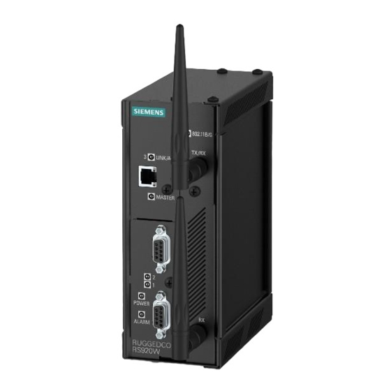
Introduction 1.1 Feature Highlights Feature Highlights Serial Interface • 2 x RS485/RS422/RS232 Serial Ports (DB9 or RJ45) • [Optional] Serial Fiber Interface (ST) Ethernet Over VDSL (EoVDSL) • 1 x Ethernet over VDSL (EoVDSL) ports • Symmetric data rates up to 35 Mbps •... - Page 12 Introduction 1.2 Description POWER LED ALARM LED EoVDSL Port Wireless Ethernet Ports Serial Ports RS232 Console Port (Serial) Failsafe Alarm Relay Chassis Ground Connection Power Supply Terminal Block Figure 1.1 RUGGEDCOM RS920W POWER LED Illuminates green during boot up and when power is supplied to the device.
-
Page 13: Required Tools And Materials
Siemens also does not recommend using copper Ethernet ports to interface with devices in the field across distances that could produce high levels of ground potential rise (i.e. greater than 2500 V), during line-to-ground fault conditions. -
Page 14: Installing The Device
This product contains no user-serviceable parts. Attempted service by unauthorized personnel shall render all warranties null and void. Changes or modifications not expressly approved by Siemens AG could invalidate specifications, test results, and agency approvals, and void the user's authority to operate the equipment. -
Page 15: General Procedure
Visually inspect each item in the package for any physical damage. Verify all items are included. Note If any item is missing or damaged, contact Siemens for assistance. Installing the Device in Hazardous Locations The RUGGEDCOM RS920W is designed to comply with the safety standards for Class I, Division 2 hazardous locations where concentrations of flammable gases, vapors or liquids may be present, as opposed to normal operating environments. -
Page 16: Mounting The Device
Installing the Device 2.4 Mounting the Device Installation and use of the device in a hazardous location should meet the following special conditions for safe use: • The equipment should be installed in an enclosure that is considered to be not accessible in normal operation without the use of a tool providing a degree of protection of not less than IP54. -
Page 17: 2.4.1 Mounting The Device On A Din Rail
Installing the Device 2.4.1 Mounting the Device on a DIN Rail 2.4.1 Mounting the Device on a DIN Rail The RUGGEDCOM RS920W can be ordered with a DIN rail adapter preinstalled on the back of the chassis. Use the adapter to mount the device to a standard 35 mm (1.4 in) IEC/EN 60715 or TS35 DIN rail. -
Page 18: Mounting The Device To A Panel
Installing the Device 2.4.2 Mounting the Device to a Panel Removing the Device To remove the device from a DIN rail, do the following: Insert a flathead screwdriver into the slot of the sliding release and move it down. DIN Rail DIN Rail Adapter Figure 2.2 Removing the Device from a DIN Rail... -
Page 19: Connecting The Failsafe Alarm Relay
Installing the Device 2.5 Connecting the Failsafe Alarm Relay Place the device against the panel and align the adapters with the mounting holes. Screw (M3.5 or #6-32) Panel Mount Adapter Figure 2.3 Panel Mounting Secure the adapters to the panel with M3.5 or #6-32 screws. Connecting the Failsafe Alarm Relay The failsafe relay can be configured to latch based on alarm conditions. -
Page 20: Connecting Power
Installing the Device 2.6 Connecting Power Connect a failsafe device to the terminal block. Normally Closed Common Normally Open Figure 2.4 Failsafe Alarm Relay Wiring Connecting Power The RUGGEDCOM RS920W supports power input from a single high AC/DC or low DC power supply. Note •... -
Page 21: 2.6.1 Connecting High Ac/Dc Power
Installing the Device 2.6.1 Connecting High AC/DC Power 2.6.1 Connecting High AC/DC Power To connect a high AC/DC power supply to the device, do the following: NOTICE Electrical hazard – risk of damage to equipment Do not connect AC power cables to terminals for DC power. Damage to the power supply may occur. - Page 22 Installing the Device 2.6.1 Connecting High AC/DC Power Connect the positive wire from the power source to the positive/live (+/L) terminal on the terminal block. Positive/Live (+/L) Terminal Negative/Neutral (-/N) Terminal Surge Ground Terminal Braided Ground Cable Figure 2.5 Terminal Block Wiring RUGGEDCOM RS920W Installation Manual, 04/2021, C79000-G8976-1033-09...
-
Page 23: 2.6.2 Connecting Low Dc Power
Installing the Device 2.6.2 Connecting Low DC Power ± ± ± ± Positive Terminal Negative Terminal Surge Ground Terminal Braided Ground Cable Figure 2.6 Terminal Block Wiring – Dual DC Power Supply Inputs Connect the negative wire from the power source to the negative/neutral (-/N) terminal on the terminal block. - Page 24 Installing the Device 2.6.2 Connecting Low DC Power Connect the positive wire from the power source to the positive terminal on the terminal block. ± ± Positive Terminal Negative Terminal Surge Ground Terminal Braided Ground Cable Figure 2.7 Terminal Block Wiring – Single DC Power Supply Inputs Connect the negative wire from the power source to the negative terminal on the terminal block.
- Page 25 Installing the Device 2.6.2 Connecting Low DC Power [Optional] If a redundant connection is required, repeat Step 2 Step 3 connect the secondary power inputs. ± ± ± ± Positive Terminal Negative Terminal Surge Ground Terminal Braided Ground Cable Figure 2.8 Terminal Block Wiring – Dual DC Power Supply Inputs Using a braided wire or other appropriate grounding wire, connect the surge ground terminal to the chassis ground connection.
-
Page 26: Device Management
Device Management This section describes how to connect to and manage the device. Connecting to the Device The following describes the various methods for accessing the RUGGEDCOM RS920W console and Web interfaces on the device. For more detailed instructions, refer to the RUGGEDCOM ROS Configuration Manual for the RUGGEDCOM RS920W. -
Page 27: Configuring The Device
Device Management 3.2 Configuring the Device The serial console port implements RS232 DCE (Data Communication Equipment) on a DB9 connector. The following is the pin-out for the port: Name Description Reserved (Do Not Connect) Transmit Data Receive Data Reserved (Do Not Connect) Signal Ground Reserved (Do Not Connect) Reserved (Do Not Connect) -
Page 28: Communication Ports
Communication Ports The RUGGEDCOM RS920W can be equipped with various types of communication ports to enhance its abilities and performance. Ports 1 and 2 Port 3 Port 9 Figure 4.1 Port Assignment Port Type 1 and 2 Serial Ports EoVDSL Port Wireless Antennas Wireless Ethernet Ports The RUGGEDCOM RS920W supports an optional set of IEEE 802.11 compliant... -
Page 29: 4.1.1 Supported Wireless Standards
Communication Ports 4.1.1 Supported Wireless Standards 4.1.1 Supported Wireless Standards Standard Parameter Mode Notes IEEE 802.11g 54 Mbps (WLAN) Full Access Point 2.4 GHz ISM IEEE 802.11b 11 Mbps (WLAN) Client support Backwards compatibility Robust Secure Strong Encryption WPA2-AES (CCMP) Network (RSN) IEEE 802.11i Enhanced Encryption WPA-TKIP (RC4) -
Page 30: Eovdsl Ports
EoVDSL line configuration settings are modified on the Master and pushed to the Slave. Data flowing from the Master to the Slave is designated downstream, while data flowing from the Slave to the Master is designated upstream. Siemens supports two types of EoVDSL: • Universal EoVDSL Universal EoVDSL ports are Master/Slave selectable and offer symmetric data rates (upstream and downstream) up to 35 Mbps. -
Page 31: Serial Ports
Communication Ports 4.3 Serial Ports IMPORTANT Universal and Long-Reach EoVDSL ports (master or slave) must be connected to EoVDSL ports (slave or master) of the same type. Connection between Universal EoVDSL ports and Long-Reach EoVDSL ports is not supported. While master/slave mode can be modified on Universal EoVDSL ports, the operating mode of all Long- Reach EoVDSL ports is predetermined by hardware. - Page 32 Communication Ports 4.3 Serial Ports Note On power-up, all serial ports default to RS485 mode. Each port can be individually set to RS232, RS485 or RS422 mode through RUGGEDCOM RS920W . For more information, refer to the RUGGEDCOM ROS Configuration Manual for the RUGGEDCOM RS920W.
- Page 33 Communication Ports 4.3 Serial Ports RUGGEDCOM RS920W Installation Manual, 04/2021, C79000-G8976-1033-09...
-
Page 34: Technical Specifications
Technical Specifications This section provides important technical specifications related to the device. Power Supply Specifications Note When determining cable lengths, make sure the minimum input voltage for the power supply is provided at the power source. Hazardous Environments Power Input Range Internal Isolation Maximum Power... -
Page 35: Failsafe Alarm Relay Specifications
Technical Specifications 5.2 Failsafe Alarm Relay Specifications Failsafe Alarm Relay Specifications Hazardous Environments Maximum Switching Voltage Rated Isolation Switching Current 30 VDC 1500 V for 1 minute 80 VDC 0.3 A 30 VAC Non-Hazardous Environment Maximum Switching Voltage Rated Isolation Switching Current 30 VDC 2 A, 60 W... -
Page 36: Operating Environment
Technical Specifications 5.5 Operating Environment Isolation 2.5 kV Fiber Serial Ports Mode Multimode Connector Typical Distance (km) Optical Wavelength (nm) Cable Size 50/125 or 62.5/125 Operating Environment The RUGGEDCOM RS920W is rated to operate under the following environmental conditions. Ambient Operating -40 to 85 °C (-40 to 185 °F) Temperature Ambient Storage Temperature... - Page 37 Technical Specifications 5.7 Dimension Drawings 65.3 116.59 7.87 Figure 5.1 Overall Dimensions RUGGEDCOM RS920W Installation Manual, 04/2021, C79000-G8976-1033-09...
- Page 38 Technical Specifications 5.7 Dimension Drawings 132.9 13.64 101.6 11.2 78.74 120.65 Figure 5.2 Panel and DIN Rail Mount Dimensions RUGGEDCOM RS920W Installation Manual, 04/2021, C79000-G8976-1033-09...
- Page 39 Technical Specifications 5.7 Dimension Drawings RUGGEDCOM RS920W Installation Manual, 04/2021, C79000-G8976-1033-09...
-
Page 40: Certification
Certification The RUGGEDCOM RS920W device has been thoroughly tested to guarantee its conformance with recognized standards and has received approval from recognized regulatory agencies. Approvals This section details the standards to which the RUGGEDCOM RS920W complies. 6.1.1 This device meets the requirements of the following Canadian Standards Association (CSA) standards under certificate 1550963: •... -
Page 41: 6.1.2 Fcc
Title 21 Code of Federal Regulations (CFR) – Chapter I – Sub-chapter J – Radiological Health 6.1.4 ISED This device is declared by Siemens AG to meet the requirements of the following ISED (Innovation Science and Economic Development Canada) standard: • CAN ICES-3 (A)/NMB-3 (A) 6.1.5... -
Page 42: Tüv Süd
Information Technology Equipment – Safety – Part 1: General Requirements 6.1.7 RoHS This device is declared by Siemens AG to meet the requirements of the following RoHS (Restriction of Hazardous Substances) directives for the restricted use of certain hazardous substances in electrical and electronic equipment: •... - Page 43 Certification 6.2 EMC and Environmental Type Tests Test Description Test Levels Severity Levels Radiated RFI Enclosure 20 V/m 61000-4-3 Ports Burst (Fast Transient) Signal Ports ± 4 kV @ 2.5 kHz 61000-4-4 DC Power ± 4 kV Ports AC Power ± 4 kV Ports Earth ±...
- Page 44 Certification 6.2 EMC and Environmental Type Tests Test Description Test Levels Severity Levels Voltage Dips and Interrupts DC Power 30% for 0.1 s 61000-4-29 Ports 60% for 0.1 s 100% for 0.05 s IEC 60255-5 Dielectric Strength Signal Ports 2 kV (Failsafe Relay Output) ...
- Page 45 Certification 6.2 EMC and Environmental Type Tests Environmental Type Tests Test Description Test Levels Severity Levels IEC 60068-2-1 Cold Temperature Test Ad -40 °C (-40 °F), 16 Hours IEC 60068-2-2 Dry Heat Test Bd 85 °C (185 °F), 16 Hours IEC 60068-2-30 Humidity (Damp Test Db...
- Page 46 Further Information Siemens RUGGEDCOM https://www.siemens.com/ruggedcom Industry Online Support (service and support) https://support.industry.siemens.com Industry Mall https://mall.industry.siemens.com Siemens AG Digital Industry Process Automation Postfach 48 48 90026 NÜRNBERG GERMANY...
Need help?
Do you have a question about the SIMATIC NET RUGGEDCOM RS920W and is the answer not in the manual?
Questions and answers