Table of Contents
Advertisement
Quick Links
SCALANCE W778-1 /W738-1
SIMATIC NET
Industrial Wireless LAN
SCALANCE W778-1 /W738-1
Operating Instructions
MSN65-W1-M12-E2
07/2019
C79000-G8976-C450-04
Introduction
Safety notices
Description of the device
Mounting
Connection
Upkeep and maintenance
Technical specifications 778-
1/W738-1
Dimension drawing
Approvals
1
2
3
4
5
6
7
8
9
Advertisement
Table of Contents

Subscribe to Our Youtube Channel
Related Manuals for Siemens SIMATIC NET SCALANCE W778-1


Summary of Contents for Siemens SIMATIC NET SCALANCE W778-1
- Page 1 SCALANCE W778-1 /W738-1 Introduction Safety notices Description of the device SIMATIC NET Mounting Industrial Wireless LAN SCALANCE W778-1 /W738-1 Connection Upkeep and maintenance Operating Instructions Technical specifications 778- 1/W738-1 Dimension drawing Approvals MSN65-W1-M12-E2 07/2019 C79000-G8976-C450-04...
- Page 2 Note the following: WARNING Siemens products may only be used for the applications described in the catalog and in the relevant technical documentation. If products and components from other manufacturers are used, these must be recommended or approved by Siemens. Proper transport, storage, installation, assembly, commissioning, operation and maintenance are required to ensure that the products operate safely and without any problems.
-
Page 3: Table Of Contents
Table of contents Introduction ............................. 5 Safety notices ............................7 Security recommendations ....................... 9 Description of the device ........................13 Description of the device ......................13 Accessories ..........................15 3.2.1 Flexible connecting cables and antennas ................18 3.2.1.1 Flexible connecting cables ...................... 18 3.2.1.2 Antennas .......................... - Page 4 Table of contents SCALANCE W778-1 /W738-1 Operating Instructions, 07/2019, C79000-G8976-C450-04...
-
Page 5: Introduction
Introduction Validity of the Operating Instructions These operating instructions cover the following products: Article number Article number US version Access points SCALANCE W778-1 M12 6GK5778-1GY00-0AA0 6GK5778-1GY00-0AB0 SCALANCE W778-1 M12 EEC 6GK5778-1GY00-0TA0 6GK5778-1GY00-0TB0 Client module SCALANCE W738-1 M12 6GK5738-1GY00-0AA0 6GK5738-1GY00-0AB0 These operating instructions apply to the following software version: ●... - Page 6 Siemens’ products and solutions undergo continuous development to make them more secure. Siemens strongly recommends that product updates are applied as soon as they are available and that the latest product versions are used. Use of product versions that are no longer supported, and failure to apply the latest updates may increase customers’...
-
Page 7: Safety Notices
Safety notices Read the safety notices Note the following safety notices. These relate to the entire working life of the device. You should also read the safety notices relating to handling in the individual sections, particularly in the sections "Installation" and "Connecting up". WARNING Hot surfaces Electric devices have hot surfaces. - Page 8 Safety notices Safety notices on use in hazardous areas General safety notices relating to protection against explosion WARNING EXPLOSION HAZARD DO NOT OPEN WHEN ENERGIZED. Safety notices when using the device according to Hazardous Locations (HazLoc) and FM. If you use the device under HazLoc or FM conditions you must also keep to the following safety notices in addition to the general safety notices for protection against explosion: This equipment is suitable for use in Class I, Division 2, Groups A, B, C and D or non- hazardous locations only.
-
Page 9: Security Recommendations
● Keep the firmware up to date. Check regularly for security updates of the product. You will find information on this on the Internet pages "Industrial Security (http://www.siemens.com/industrialsecurity)". ● Inform yourself regularly about security advisories and bulletins published by Siemens ProductCERT (http://www.siemens.com/cert/en/cert-security-advisories.htm). ● Only activate protocols that you really require to use the device. - Page 10 Safety notices 2.1 Security recommendations ● Use a central logging server to log changes and access operations. Operate your logging server within the protected network area and check the logging information regularly. ● Use WPA2/ WPA2-PSK with AES to protect the WLAN. If iPCF or iPCF-MC is used, use the AES encryption.
- Page 11 Safety notices 2.1 Security recommendations Secure/non-secure protocols and services ● Avoid and disable non-secure protocols, for example Telnet and TFTP. For historical reasons, these protocols are still available, however not intended for secure applications. Use non-secure protocols on the device with caution. ●...
- Page 12 Safety notices 2.1 Security recommendations ● Port status – Open The port is always open and cannot be closed. – Open (when configured) The port is open if it has been configured. ● Factory setting – Open The factory setting of the port is "Open". –...
-
Page 13: Description Of The Device
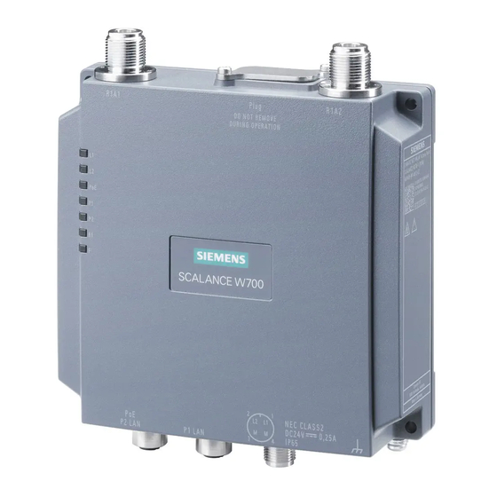
Description of the device Description of the device W778-1 /W738-1 M12 ① LED display ② Antenna connector R1A1 ③ PLUG slot / RESET button ④ Antenna connector R1A2 ⑤ Grounding ⑥ Connector for power supply (L1, L2) ⑦ Ethernet connector P1 ⑧... - Page 14 ● SIMATIC NET Industrial Wireless LAN CD Please check that the consignment you have received is complete. If the consignment is incomplete, contact your supplier or your local Siemens office. Note The mounting adapter and the bracket for installation on a DIN rail does not ship with the product, see Accessories (Page 15).
-
Page 15: Accessories
Description of the device 3.2 Accessories Accessories Technical data subject to change. You will find further information on the range of accessories in the Industry Mall (https://mall.industry.siemens.com) PLUG Component Description Article number C-PLUG Configuration PLUG Exchangeable storage medium for configuration data. - Page 16 Description of the device 3.2 Accessories Cables Industrial Ethernet Component Description Article number IE FC TP STANDARD Standard bus cable, TP installation cable for con- 6XV1840-2AH10 CABLE GP2X2 nection to FC OUTLET RJ-45, for universal use, 4- wire, shielded, CAT 5E (PROFINET type A) Sold by the meter IE FC TP ROBUST...
- Page 17 Description of the device 3.2 Accessories Component Description Article number N-Connect/N- Panel feedthrough for wall thicknesses up to a maxi- 6GK5798-2PP00-2AA6 Connect fe- mum of 4.5 mm, two N-Connect female connectors. male/female Panel Feed- through Panel feedthrough for wall thicknesses up to a maxi- 6GK5798-0PT00-2AA6 Connect/SMA- mum of 5.5 mm, two N-Connect/SMA female connect-...
-
Page 18: Flexible Connecting Cables And Antennas
Description of the device 3.2 Accessories Lightning protection Component Description Article number LP798-1N Lighting protector with N/N female/female connector 6GK5798-2LP00-2AA6 with gas discharge technology LP798-2N Lighting protector with N/N female/female connector 6GK5798-2LP10-2AA6 with quarter wave technology Terminating resistor Component Description Article number TI795-1N Electrical connection... -
Page 19: Antennas
Article number 6XV1875-5VH10 3.2.1.2 Antennas Note When you select an antenna, keep in mind the national approvals for your device. You will find more detailed information in Link (http://www.siemens.com/wireless-approvals). Type Properties Article number ANT792-4DN RCoax helical antenna, circular polarization, 6GK5792-4DN00-0AA6 4 dBi, 2.4 GHz, N-Connect female. - Page 20 Description of the device 3.2 Accessories Type Properties Article number ANT792-8DN Directional antenna, mast/wall mounting, 14 6GK5792-8DN00-0AA6 dBi 2.4 GHz, N-Connect female ANT793-6DG Wide angle antenna, mast/wall mounting, 9 6GK5793-6DG00-0AA0 dBi 5 GHz, 2 x N-Connect female ANT793-6MN Omni antenna, mast/wall mounting, 5 dBi 5 6GK5793-6MN00-0AA6 GHz, N-Connect female ANT793-8DJ...
- Page 21 Description of the device 3.2 Accessories Type Properties Article number IWLAN RCoax Cable Omni antenna, 0 dBi 2.400 - 2.485 GHz, N- 6XV1875-2A 2,4 GHz PE 1/2" Connect female IWLAN RCoax Cable Omni antenna, 0 dBi 5.150 – 5.875 GHz, N- 6XV1875-2D 5 GHz PE 1/2"...
-
Page 22: Led Display
Description of the device 3.3 LED display LED display Information on operating status and data transfer On the front of the housing, several LEDs provide information on the operating status of the device: Color Meaning Power supply too low Green Power supply is applied Power supply too low Green... - Page 23 Description of the device 3.3 LED display Color Meaning There is no connection over the Ethernet port P1. Green There is no connection over the Ethernet port P1. (Link) Flashing green Data transfer over the Ethernet interface P1. and yellow There is no connection over the Ethernet port P2.
- Page 24 Description of the device 3.3 LED display Color Meaning An error occurred during operation with the device. A primary user was found on all enabled channels. Simultaneous R1 yellow flash- Flashing red An upgrade/downgrade of the firmware is installed from the plug: Afterwards the device is restarted and the device configuration incl.
-
Page 25: Reset Button
Description of the device 3.4 Reset button Reset button Position NOTICE Loss of water and dust protection If the cover is not mounted correctly, the device is not water and dust proof. ① The reset button is located below the cover ( ) on the top of the SCALANCE W778 / 738. - Page 26 Description of the device 3.4 Reset button Functions of the reset button The reset button has the following functions: ● Restart of the device To restart the device, press the reset button briefly. Note If you make changes to the configuration and restart immediately afterwards with the reset button, the changes may be lost.
-
Page 27: Mounting
Mounting Safety notices for installation Safety notices When installing the device, keep to the safety notices listed below. CAUTION Minimum distance to antennas Fit the device so that there is a minimum clearance of 20 cm between antennas and persons. WARNING If the device is installed in a cabinet, the inner temperature of the cabinet corresponds to the ambient temperature of the device. - Page 28 Mounting 4.1 Safety notices for installation WARNING The device may only be operated in an environment with pollution degree 1 or 2 (see IEC 60664-1). WARNING When used in hazardous environments corresponding to Class I, Division 2 or Class I, Zone 2, the device must be installed in a cabinet or a suitable enclosure.
-
Page 29: Types Of Installation
Mounting 4.2 Types of installation Types of installation Note • The device is only approved for operation in closed rooms. Note the following environmental conditions. • Antennas, in particular directional antennas, must be mounted in keeping with their characteristics (refer to the technical specifications of the antenna --> Radiation pattern diagrams). -
Page 30: Wall Mounting
Mounting 4.3 Wall mounting Wall mounting Note Depending on the mounting surface, use suitable fittings. Note The wall mounting must be capable of supporting at least four times the weight of the device. To mount the device on a wall, follow the steps below: 1. -
Page 31: Installation On A Din Rail
Mounting 4.4 Installation on a DIN rail Installation on a DIN rail 4.4.1 Installation with the DIN rail mounting adapter The DIN rail mounting adapter is not included with the product, see Accessories. Assembly 1. Screw the DIN rail mounting adapter to the rear of the device. - Page 32 Mounting 4.4 Installation on a DIN rail 3. Press the device against the DIN rail until the DIN rail slider catch locks in place. 4. Connect the power supply, refer to the section "Power supply (Page 41)". 5. Fit the antennas, refer to the section "Antennas (Page 45)". Uninstalling 1.
-
Page 33: Mounting With Bracket Support
Mounting 4.4 Installation on a DIN rail 4. Tilt the device forward and remove the device from the DIN rail. 5. Loosen the screws of the DIN rail mounting adapter completely. 4.4.2 Mounting with bracket support With the bracket support the device can be mounted on a DIN rail rotated through 90° The DIN rail mounting adapter and bracket holder are not included with the product, see Accessories (Page 15). - Page 34 Mounting 4.4 Installation on a DIN rail Installation 1. Screw (M3, tightening torque 0.7 Nm) the bracket holder to the DIN rail mounting adapter . The mounting material ships with the product. 2. Screw (tightening torque 0.7 Nm) the bracket holder to the side of the device.
- Page 35 Mounting 4.4 Installation on a DIN rail 4. Press the device against the DIN rail until he DIN rail slider catch locks in place. 5. Connect the power supply, refer to the section "Power supply (Page 41)". 6. Fit the antennas, refer to the section "Antennas (Page 45)". Uninstalling 1.
- Page 36 Mounting 4.4 Installation on a DIN rail 4. Tilt the device forward and remove the device from the DIN rail. 5. Loosen the screws completely. SCALANCE W778-1 /W738-1 Operating Instructions, 07/2019, C79000-G8976-C450-04...
-
Page 37: Connection
Connection Safety when connecting up Safety notices When connecting up the device, keep to the safety notices listed below. Note Strain relief for the Ethernet cables In order to avoid mechanical stress on the Ethernet cables and resulting interruption of the contact, fasten the cables at a short distance from the connector using a cable guide or busbar. - Page 38 Connection 5.1 Safety when connecting up Suitable lightning protectors are available in the accessories (Page 15) of SIMATIC NET Industrial WLAN. Note We recommend that you use the maintenance-free lightning protector LP798-2N. Exception: When there is also DC power supplied via the antenna cable. In this case, only the lightning protector LP798-1N can be used.
- Page 39 Connection 5.1 Safety when connecting up Grounding WARNING Danger to life from overvoltage, fire hazard When using outdoor antennas, the shared or even grounded pin of the circuit must be connected to the shield of the coaxial cable and with all touchable conductive parts and circuits.
- Page 40 Connection 5.1 Safety when connecting up WARNING EXPLOSION HAZARD Do not press the reset button if there is a potentially explosive atmosphere. WARNING Suitable cables at high ambient temperatures If the temperature of the cable or housing socket exceeds 70 °C or the branching point of conductors exceeds 80 °C, special precautions must be taken.
-
Page 41: Power Supply
Connection 5.2 Power supply Power supply Note Galvanic isolation of the power supply unit To ensure dielectric strength according to IEEE 802.3, the supplying 24 V power supply unit must be galvanically isolated with a dielectric strength of 1500 VAC. The galvanic isolation must also not be bridged by other devices connected to the same power supply unit. - Page 42 Connection 5.2 Power supply Position and pin assignment ① M12 interfaces, A-coded ② M12 interface P2, D-coded The power can also be supplied via this interface (Power over Ethernet). The four-pin M12 socket has the following pin assignment: Signal Assignment 24 VDC 24 VDC Ground...
- Page 43 Connection 5.2 Power supply Power over Ethernet Note Disabling the PoE power supply Before you pull a plug via which the device is supplied with power using PoE, disable the relevant PoE power supply. Note "Phantom power" only with SCALANCE W778/W738 The SCALANCE W778/W738 device supports only the standard IEEE 802.3at/af mode A..
-
Page 44: Ethernet
Connection 5.3 Ethernet Ethernet For connection to Industrial Ethernet at 10/100 Mbps, the the SCALANCE W7x8 devices have the following two M12 interfaces: D-coded, 4-pin. Position and pin assignment ① M12 interface P1 ② M12 interface P2 The power can also be supplied via this interface (Power over Ethernet). The four-pin connecting socket has the following pin assignment: Assignment Connecting Ethernet ports... -
Page 45: Antenna Connector
Connection 5.4 Antenna connector Antenna connector The SCALANCE W778/W738 has two antenna connectors of the type N-Connect located on the top of the device. Figure 5-1 Antenna connectors ① Antenna connector R1 A1 ② Antenna connector R1 A2 Procedure Follow the steps below to connect a cable for an external antenna: 1. - Page 46 Connection 5.4 Antenna connector NOTICE UL approval only for use in buildings Within the area of authority of the NEC and CEC, the SCALANCE W778/W738 devices and the antennas connected to them may only be used in a closed building. For this reason, do not lead antennas into the outdoor area if you need to meet UL or CSA requirements.
-
Page 47: Replacing The Plug (C-Plug Or Key-Plug)
Connection 5.5 Replacing the PLUG (C-PLUG or KEY-PLUG) Replacing the PLUG (C-PLUG or KEY-PLUG) NOTICE Do not remove or insert a C-PLUG / KEY-PLUG during operation! A PLUG may only be removed or inserted when the device is turned off. The device checks whether or not a PLUG is inserted at one second intervals. - Page 48 Connection 5.5 Replacing the PLUG (C-PLUG or KEY-PLUG) Removing the PLUG Follow the steps below to remove a PLUG from the device: 1. Turn off the power to the device. 2. Release the screw of the slot cover and swing the slot cover to the side. 3.
- Page 49 Connection 5.5 Replacing the PLUG (C-PLUG or KEY-PLUG) Licenses on the KEY-PLUG A C-PLUG only stores information about the configuration of a device. In addition to the configuration, a KEY-PLUG also contains a license with which you can enable special functions, for example iFeatures.
-
Page 50: Grounding
Connection 5.6 Grounding Grounding EMC disturbances are diverted to ground via the functional ground. This ensures the immunity of the data transmission. The grounding screw is identified by the following symbol for the functional ground Protective earth/functional ground The connection of the reference potential surface with the protective earth system is normally in the cabinet close to the power feed-in. -
Page 51: Upkeep And Maintenance
Upkeep and maintenance Device configuration with PRESET-PLUG Please not the additional information and security notes in the operating instructions of your device. NOTICE Do not remove or insert a PLUG during operation A PLUG may only be removed or inserted when the device is turned off. Note Support as of V6.0 The PRESET-PLUG functionality is supported as of firmware version V6.0. - Page 52 Upkeep and maintenance 6.1 Device configuration with PRESET-PLUG Procedure 1. Start the remote configuration using Telnet (CLI) and log on with a user with the "admin" role. 2. Change to the Global configuration mode with the command "configure terminal". 3. You change to the PLUG configuration mode with the "plug" command. 4.
- Page 53 Upkeep and maintenance 6.1 Device configuration with PRESET-PLUG Note Restore factory defaults and restart with a PRESET PLUG inserted If you reset a device to the factory defaults, when the device restarts an inserted PRESET PLUG is formatted and the PRESET PLUG functionality is lost. You then need to create a new PRESET PLUG.
-
Page 54: Downloading New Firmware Using Tftp Without Wbm And Cli
Upkeep and maintenance 6.2 Downloading new firmware using TFTP without WBM and CLI Downloading new firmware using TFTP without WBM and CLI You can download new firmware to the device using TFTP. To do this, the device does not need to be reachable either using Web Based Management (WBM) or using the Command Line Interface (CLI). -
Page 55: Restoring The Factory Settings
Upkeep and maintenance 6.3 Restoring the factory settings Restoring the factory settings NOTICE Previous settings If you reset, all the settings you have made will be overwritten by factory defaults. NOTICE Inadvertent reset An inadvertent reset can cause disturbances and failures in a configured network with further consequences. - Page 56 Upkeep and maintenance 6.3 Restoring the factory settings Via the configuration You will find detailed information on resetting the device parameters using the WBM and CLI in the configuration manuals: ● Web Based Management, section "Restart" ● Command Line Interface, section "Reset and Defaults" SCALANCE W778-1 /W738-1 Operating Instructions, 07/2019, C79000-G8976-C450-04...
-
Page 57: Technical Specifications 778-1/W738-1
Technical specifications 778-1/W738-1 ● SCALANCE W738-1 M12 ● SCALANCE W778-1 M12 ● SCALANCE W778-1 M12 EEC Note You will find detailed information on the transmit power and receiver sensitivity in the document "Performance data 802.11 abgn SCALANCE W770/W730" on the supplied data medium (REF_W770-RadioInterface.pdf). - Page 58 Technical specifications 778-1/W738-1 Technical specifications Wireless interface Antenna connector Quantity Design N-Connect socket Impedance 50 Ω nominal Frequency range 2412 ... 2480 MHz 4920 ... 5875 MHz Electrical data Direct 24 VDC supply Supply voltage from socket 24 VDC Safe Extra Low Voltage (SELV) Permitted range +/- 30 % 16.8 to 31.2 VDC...
- Page 59 Technical specifications 778-1/W738-1 Technical specifications Installation options Direct: Wall mounting With additional holding plate Installation on a DIN rail with DIN rail mounting adapter • with additional bracket support for installation rotated though 90° • Mean time between failure (MTBF) at 40 °C ambient temperature 61 years SCALANCE W778-1 /W738-1...
- Page 60 Technical specifications 778-1/W738-1 SCALANCE W778-1 /W738-1 Operating Instructions, 07/2019, C79000-G8976-C450-04...
-
Page 61: Dimension Drawing
Dimension drawing Note Dimensions are specified in mm. Front view Width, height and dimensions for wall mounting SCALANCE W778-1 /W738-1 Operating Instructions, 07/2019, C79000-G8976-C450-04... - Page 62 Dimension drawing Side view Figure 8-1 Side view W778 / W738 See also Wall mounting (Page 30) SCALANCE W778-1 /W738-1 Operating Instructions, 07/2019, C79000-G8976-C450-04...
-
Page 63: Approvals
Approvals You will find the approvals of the products in the reference work "Approvals SCALANCE W700 802.11n" on the Internet pages of Siemens Industry Online Support: ● Using the search function at Siemens Industry Online Support (https://support.industry.siemens.com/cs/ww/en/) ● Using the search function at Industrial communication (https://support.industry.siemens.com/cs/ww/en/ps/15859/cert) - Page 64 Approvals Taiwan: NCC "WARNINGS" (English) Article 12 Without permission, any company, firm or user shall not alter the frequency, increase the power, or change the characteristics and functions of the original design of the certified lower power frequency electric machinery Article 14 The application of low power frequency electric machineries shall not affect the navigation safety nor interfere a legal communication, if an interference is found, the service will be...
-
Page 65: Index
Index A-coded, 41 KEY-PLUG, 47 Antenna cables, 18 Antennas, 18 Connectors, 45 LED display, 22 Lightning protection, 37 Button Reset, 25 Power supply Connecting up, 41 Primary user (radar), 22 Cables Protective caps, 14 Permitted lengths, 57 Components of the product, 14 Configuration manuals, 56 C-PLUG, 47 Reset device, 26, 26, 55... - Page 66 Index SCALANCE W778-1 /W738-1 Operating Instructions, 07/2019, C79000-G8976-C450-04...
Need help?
Do you have a question about the SIMATIC NET SCALANCE W778-1 and is the answer not in the manual?
Questions and answers