
Related Manuals for KEB COMBISTOP


Summary of Contents for KEB COMBISTOP
- Page 1 COMBISTOP INSTRUCTION MANUAL | Type 38 SPRING SET BRAKE Original manual COMBISTOP type 38 Document 20243560 000 01...
- Page 2 2021 KEB America, Inc. ©...
-
Page 3: Preface
The hardware and software described in this document are products of KEB America, Inc. The information contained in this document is valid at the time of publishing. KEB reserves the right to update this document in response to misprints, mistakes or technical changes. -
Page 4: Laws And Requirements
→ Further information is provided in Appendix A: Certification. 1.4 Warranty KEB Automation KG provides a limited warranty on all products. This warranty can be found in the terms and conditions at our website. KEB America, Inc. Terms and Conditions Terms and Conditions Further agreements or specifications require written confirmation from KEB America, Inc. -
Page 5: Table Of Contents
Copyright ......................4 Table of Contents ....................... 5 List of Figures......................8 Glossary ........................9 Standards for COMBISTOP type 38 Brakes ............12 2 Safety Instructions ................13 Target Audience ..................... 13 Specified Application ..................13 General Safety Guidelines ................14 Electrical Safety Guidelines ................ - Page 6 Before You Begin ................... 41 7.1.1 Running-In Process ......................41 Manual Operation ................... 42 8 Maintenance and Troubleshooting ........... 43 Maintenance ....................43 8.1.1 Checking the Air Gap ......................43 8.1.2 Adjusting the Air Gap ......................45 2021 KEB America, Inc. ©...
- Page 7 8.1.3 Replacing the Friction Lining ....................46 Torque Adjustment ..................47 Troubleshooting ..................... 48 9 Appendix ....................49 Appendix 1: Technical Specifications ............49 Appendix 2: Certification ................50 Appendix 3: Revision History ............... 51 2021 KEB America, Inc. ©...
-
Page 8: List Of Figures
Figure 18 Adjust the Air Gap ........................45 Figure 19 Removing the Magnet System ....................46 Figure 20 Size 02 - 06 with E-Ring ......................47 Figure 21 Size 07 - 11 with Set Screws ...................... 47 2021 KEB America, Inc. ©... -
Page 9: Glossary
If the air gap is too narrow, the brake may not release correctly. Application The machine/system in which the KEB device is to be used. For brakes the application is typically the motor to which the brake is attached. - Page 10 KEB. KEB Automation KG Parent company of KEB America, Inc. Also referred to as KEB. Load The components of a mechanical system driven by a motor. The load refers to the entire system powered by the motor.
- Page 11 Preface Specified Application The specific application for which the COMBISTOP device was ordered, is usually (but not always) the same as the Application in which the device is being used. System Integrator The technician installing the COMBISTOP brake into the application.
-
Page 12: Standards For Combistop Type 38 Brakes
Glossary Standards for COMBISTOP type 38 Brakes The COMBISTOP installation must comply with all relevant safety standards. The following standards are relevant to the installation and operation of the COMBISTOP type 38 Brake. Directive 2006/42/EC (annex I) • Region: EU Essential health and safety requirements for the design and construction of machinery. -
Page 13: Safety Instructions
The following safety instructions have been created by KEB America, Inc. for the COMBISTOP type 38 brake. These instructions can be supplemented by local, country- or application-specific safety instructions where relevant. -
Page 14: General Safety Guidelines
• Never use the brake in potentially explosive environments. • The brake may not be modified or altered in any way not intended by KEB America, Inc. 2.4 Electrical Safety Guidelines Rick of electrical shock! DANGER Turn off the power supply and secure it against switching on prior to any work on the device. -
Page 15: Maintenance Safety Guidelines
Ensure there is sufficient protection against foreign particles entering the air gap during • maintenance. Ensure there is sufficient protection against moisture or aggressive gasses that may • compromise the integrity of the friction surface or armature. 2021 KEB America, Inc. ©... -
Page 16: Personal Protective Equipment
Safety shoes • Safety goggles • The personal protective equipment must be provided by the operating company and must comply with any applicable safety regulations. → See Standards for COMBISTOP type 38 Brakes for details. 2021 KEB America, Inc. ©... -
Page 17: Permissible Friction Work
Permissible Friction Work Values Size Range Speed 00 – 07 3000 rpm 08 – 11 1500 rpm Figure 1 Friction Switching Frequency Red line for brake without friction disk 2021 KEB America, Inc. ©... -
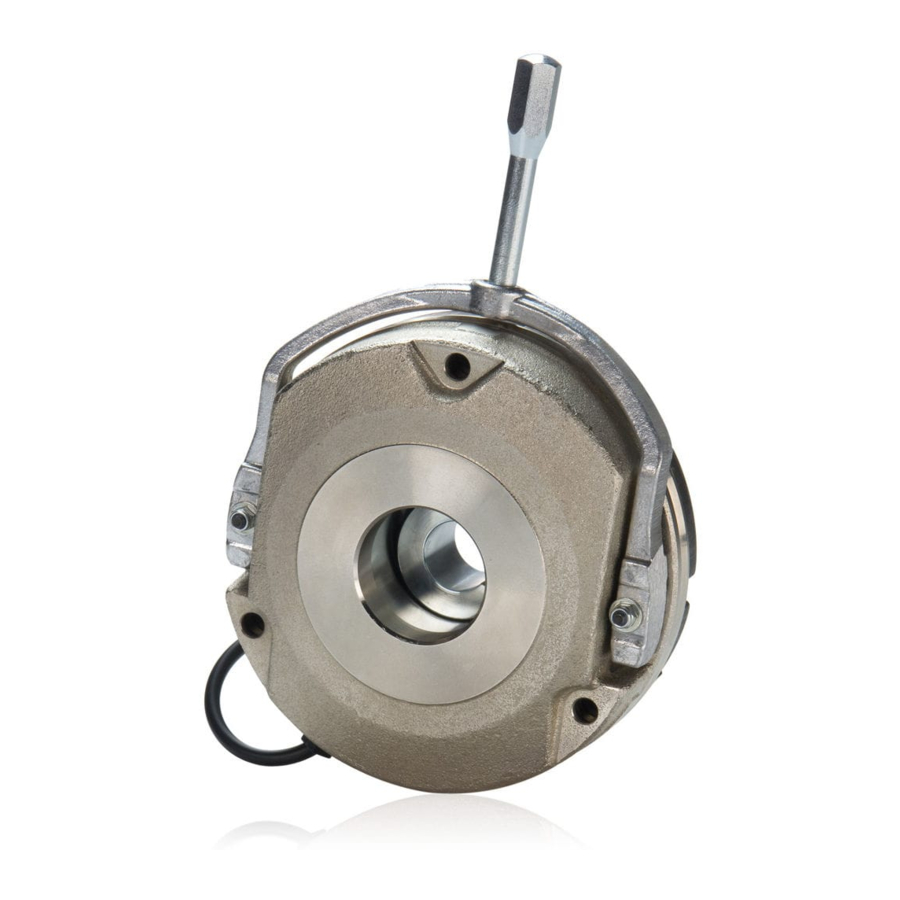
Page 18: Product Description
3 Product Description 3.1 Scope of this Manual This manual provides all information required to properly install and operate the KEB COMBISTOP type 38 Spring Set Brake. This manual applies to the following brake types: • COMBISTOP type 38.11N Without hand release for dynamic applications (regular rated torque) COMBISTOP type 38.13N... -
Page 19: Torque And Operating Power
Product Description 3.3 Torque and Operating Power The COMBISTOP comes in a variety of sizes to meet the braking needs of the specified application. Braking torque and operating power by brake size is shown below. Brake Rated Braking Torque Wattage... -
Page 20: Parts List
Splined Hub (for size B brakes) Molded Friction Lining (for size A brakes) Splined Friction Lining with Aluminum Carrier (for size B brakes) Friction Disk (Optional) Flange (Optional) Hand Release Lever (Optional) Dust Protection Ring (Optional) 2021 KEB America, Inc. ©... -
Page 21: Optional Safety Devices
The hand release lever can be installed to provide manual release of the brake in the case of power outages or malfunctions. The COMBISTOP type 38 brake engages when powered off, so in the case of a power outage the brake will bring the system to a safe halt. -
Page 22: Transport And Storage
Report any shipping damage to the device or packing to the shipping company and to KEB America, Inc. 4.2 Unloading and Moving the Device Large sizes of the COMBISTOP brake can be too heavy to safely move by hand. Use appropriate lifting devices to transport large size COMBISTOP devices. →... -
Page 23: Installation
Friction surfaces made of cast iron or steel are best suited for the COMBISTOP type 38. If a suitable friction surface is not available, an optional flange or friction disk can be installed between the COMBISTOP and the mounting surface. -
Page 24: Mounting Surface Requirements
0.08 (mm) 5.3 Installing the Brake The following steps detail installing the COMBISTOP brake. For visual examples of installing the brake and adjusting the air gap you can view a tutorial video at the following link. Installation Video on Youtube... -
Page 25: Figure 5 Mounting The Hub
Ensure the hub cannot run against the friction surface! KEB America, Inc. recommends leaving a space of 0.5mm to 1mm between hub and friction surface to prevent friction and wear and tear on the hub. - Page 26 If the brake includes a lifting tab (Size 10), remove the lifting tab by removing the fastening screws after securely attaching the magnet system. The following table shows screw number and sizes for each size of COMBISTOP brake. Size...
-
Page 27: Figure 7 Air Gap
Figure 7 Air Gap Size Xn [mm] Connect the COMBISTOP brake lead lines to an appropriate DC voltage to test brake function. The brake will release when voltage is applied, and engage when the voltage supply is powered off. The COMBISTOP brake is now ready for use. -
Page 28: Electrical Connection
Powering the brake outside of the nominal DC voltage will damage the brake. The COMBISTOP type 38 brake must be powered by a nominal DC voltage. If such a voltage is not available, an AC to DC rectifier is available for purchase from KEB America, Inc. -
Page 29: Ac Side Switching
AC voltage. 125VAC for 120V supply and 250VAC for 208 and 230V supplies. Rectifier Models Rectifier Models 0491010-CE07 0491010-CE07 0491020-CE07 0491020-CE07 Figure 9 Rectifier Wiring: Motor Supply Figure 8 Rectifier Wiring: Independent Supply Rectifier Model 0691010-CE07 Figure 10 Rectifier Wiring: Phase to Phase 2021 KEB America, Inc. ©... -
Page 30: Dc Side Switching
(Kbrk_dc) must be a three way phase power contactor rated for 600VAC and minimum of 9 amps inductive (AC3). All three contacts are wired in series as indicated in figure 11. Rectifier Models 0491010-CE07 0491020-CE07 Figure 11 Rectifier Wiring: DC Switching 2021 KEB America, Inc. ©... -
Page 31: Dc Side Switching With External Mov
Figure 12 Rectifier Wiring: External MOV The following MOVs are recommended for use with the listed supply voltage. Supply Voltage KEB Material Number Varistor Voltage 120V, 208V, 230V, 240V 0090045-2753 275VACrms 400V, 480V 0090045-6255 625VACrms 2021 KEB America, Inc. ©... -
Page 32: Switching Cycles And Times
1200 350/400 1400 1800/2000 60/100 250/300 3100 3500 1000 1) rated torque after running in process Numbers in are for COMBISTOP designation N, H, where applicable applicable for rectifiers: applicable for recifiers: 0210010-CE07 0491010-CE07 0291020-CE07 0491020-CE07 0291010-CEMV 0591010-CE09 0691010-CE09 Maximal permissable switching cycle [min At DC-side switching and max. - Page 33 Installation Current-Time / Voltage-Time / Torque-Time Diagrams AC Side Switching DC Side Switching = Engagement Time = Engagement Delay Time = Release Time 2021 KEB America, Inc. ©...
-
Page 34: Uninstallation Of The Brake
Category Key Number Magnet with coil, cables, Steel scrap EAK 12 01 02 and all other steel parts Aluminum components Nonferrous metals EAK 16 01 18 including copper Lining Brake linings EAK 16 01 12 2021 KEB America, Inc. ©... -
Page 35: Optional Components
(N or H) and the size of the brake. Refer to the following table to see which parts are included for each size/design of COMBISTOP. Figure 13 Hand Release Lever Parts 2021 KEB America, Inc. -
Page 36: Installing The Hand Release Lever
9 and 10 as shown in the lower line of the image. Power ON the magnet and adjust the hex nuts (8) until the gap between locking plate/washer (5/6) and armature is equal to the adjustment dimension m. 2021 KEB America, Inc. ©... - Page 37 If you are operating the brake with different values than those listed in this manual, contact KEB America, Inc. for adjusted m dimensions. Verify the air gap X is set to the adjusted dimension as shown on the table above.
-
Page 38: Microswitch
Microswitch to prevent any movement from the shaft while performing work on the brake. Figure 14 Microswitch Parts The image shown above is one example of microswitch assembly. Consult KEB America, Inc. for detailed information for your specific brake. 2021 KEB America, Inc. ©... -
Page 39: Microswitch Replacement
After installation, verify the switching point for the microswitch by repeatedly powering the brake ON and OFF. Verify the two switching states. If necessary adjust the microswitch. Brake Energized: ON signal (microswitch closed) Brake De-Energized: OFF signal (microswitch open) → See section Adjusting the Microswitch Settings. 2021 KEB America, Inc. ©... -
Page 40: Adjusting The Microswitch Settings
Microswitch to prevent any movement from the shaft while performing work on the brake. The procedure shown below is one example of microswitch adjustment. Consult KEB America, Inc. for detailed information for your specific brake. Loosen the hex-head lock-nut (5). -
Page 41: Operation
Operation 7 Operation The operation of the COMBISTOP brake is performed by the control device provided by the customer. The COMBISTOP brake can be manually controlled with the optional Hand Release Lever. 7.1 Before You Begin Prior to the initial start-up of the system, go through the following checklist to ensure the brake will function properly. -
Page 42: Manual Operation
To disengage the brake using the hand release lever, steadily pull the lever directly away from the mounting surface until the brake is released, as shown below. Figure 15 Hand Release Lever Operation 2021 KEB America, Inc. ©... -
Page 43: Maintenance And Troubleshooting
8.1 Maintenance The COMBISTOP type 38 brake is almost maintenance-free. As a result of wear occurring during operation, the air gap between magnet and armature increases and the friction lining wears away. -
Page 44: Figure 17 Wear Dimensions
The minimum permissible thickness of the friction lining before replacement is denoted Gmin. • The hub counter bore is denoted R and shown above. • Size X [mm] V [mm] Xn [mm] Gmin [mm] R [mm] Design 10.0 10.0 10.0 11.0 12.0 14.0 22.0 2021 KEB America, Inc. ©... -
Page 45: Adjusting The Air Gap
Gmin, the friction lining should be replaced. Once the air gap is adjusted, check the socket-head screws to ensure they are secure, and return the brake to operation. → See Installing the Brake for details. 2021 KEB America, Inc. ©... -
Page 46: Replacing The Friction Lining
Replace the magnet system onto the shaft and replace the socket-head screws. Check the air gap X, and adjust if necessary. → See section Checking the Air Gap, and section Adjusting the Air Gap. 2021 KEB America, Inc. ©... -
Page 47: Torque Adjustment
E-Ring can be rotated to adjust the torque. • COMBISTOP sizes 07 – 11 use set screws to reduce braking torque. All set screws should be turned the same number of rotations to ensure even braking torque. Figure 20 Size 02 - 06 with E-Ring... -
Page 48: Troubleshooting
Maintenance and Troubleshooting 8.3 Troubleshooting The following are some common issues that may occur with the COMBISTOP type 38 brake, as well as steps to resolving these issues. Before performing any troubleshooting, follow all relevant safety guidelines. → See section Maintenance Safety Guidelines for details. -
Page 49: Appendix
IP44 (with optional dust Protected from solid objects bigger protection ring) than 1mm and water splashes from all directions. For more technical data including dimensions, rated torques, power input etc., refer to the KEB product catalogue. 2021 KEB America, Inc. ©... -
Page 50: Appendix 2: Certification
Appendix 9.2 Appendix 2: Certification 2021 KEB America, Inc. ©... -
Page 51: Appendix 3: Revision History
Appendix 9.3 Appendix 3: Revision History Chapter Change Date Manual Initial Publication 12/2020 Added Comprehensive Rectifier Details 05/2021 2021 KEB America, Inc. ©... - Page 52 Internet: www.keb.jp Belgium | KEB America, Inc. P.R. China | KEB Power Transmission Technology (Shanghai) Herenveld 2 9500 Geraardsbergen Belgium Co. Ltd. No. 435 QianPu Road Chedun Town Songjiang District Tel: +32 544 37860 Fax: +32 544 37898 201611 Shanghai P.R. China E-Mail: vb.belgien@keb.de...
- Page 53 Automation with Drive www.kebamerica.com KEB America, Inc. 5100 Valley Industrial Blvd S Shakopee, MN 55379 Tel. +1 952-224-1400 E-Mail: info@kebamerica.com...
Need help?
Do you have a question about the COMBISTOP and is the answer not in the manual?
Questions and answers