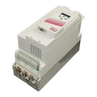
KEB COMBIVERT R6 Instruction Manual
Hide thumbs
Also See for COMBIVERT R6:
- Instruction manual (60 pages) ,
- Instructions for use manual (72 pages) ,
- Instruction manual (56 pages)

Related Manuals for KEB COMBIVERT R6


Summary of Contents for KEB COMBIVERT R6
- Page 1 C O M B I V E R T GB Instruction Manual Power supply and regenerative unit Type R6-S Size 15/19 Mat.No. Rev. 00R6SEB-K000...
- Page 2 This instruction manual describes the power supply and regenerative unit KEB COMBIVERT R6-S series. Before working with the unit the user must become familiar with it. This especially applies to the knowledge and observance of the following safety and warning indications. The pictographs used in this instruc- tion manual have following meaning: GB - 3 …...
-
Page 3: Table Of Contents
4.4.6 Power supply /regenerative operation at parallel operation of COMBIVERT R6-S with recovery contactor ............................21 4.4.7 Regenerative operation at parallel operation of COMBIVERT R6-S with decoupling diodes ... 22 Connection of the control board version S .................. 23 4.5.1 Assignment of the control terminal strip X2A ..................23 4.5.2 Assignment of socket X2B ........................ -
Page 4: Introduction
• is cost-saving. The COMBIVERT R6-S is generally protected against overcurrent, ground fault and tempera- ture. Appropriate dimensioned DC fuses protects the DC link circuit against short-circuit. The following accessories are necessary for operation with the COMBIVERT R6-S: •... -
Page 5: Specified Application
Preface 1.3 Specified application The COMBIVERT R6-S serves exclusively for the supply of frequency inverters with DC input and/or feedback of excess energy into the supply system. The operation of other electrical consumers is prohibited and can lead to malfunctions or to the destruction of the units. -
Page 6: Safety Instructions
COMBIVERT R6 power supply und regenerative units contain dangerous voltages which can cause death or serious injury. COMBIVERT R6 can be adjusted by way that energy is refeed into the supply system in case of power failure at generatoric operation. Therefore a dangerous high tension can be in the unit after switching off the supply system. -
Page 7: Electrical Connection
This is permissible in compliance with the standard, Insulation Mea- since all inverters are given a high voltage test in the end control at KEB in accordance with surement EN 50178. When using components without isolated inputs/outputs, it is necessary that equipotential bonding exists between the components to be connected (e.g. - Page 8 Safety Instructions A trouble-free and safe operation of the COMBIVERT R6 is only guaranteed when the con- nection instructions below are strictly followed. Incorrect operation or damage may result from incorrect installation. • Pay attention to mains voltage. • • Install power cables and control cables separately (>15 cm separation).
- Page 9 Safety Instructions If personnel protection of the system is required, the COMBIVERT R6-S must be protected according to EN 61800-5-1: • • 3-phase inverters (with B6 bridge-connected rectifier) by RCMA’s with separation (used privileged) or RCD’s type B (all-current sensitive FI’s) The tripping current should be 300mA or more, in order to avoid a premature triggering by discharge currents (about 200mA. Dependent on the load, the length of the motor cable and the use of a radio interference filter, substantially higher leakage current can occur.
-
Page 10: Emc Instructions
Keep connection cables straight (do not bundle). Install a non-assigned wire at one sides to the protective earth conductor. • The flow and return circuit must be twisted when the lines are not shielded, in order to dampen common-mode noise. • The cable for phase synchronisation between mains choke and COMBIVERT R6-S may not exceed a line length of 1 m. • Further informations are found in the internet, see „www.keb.de“. -
Page 11: Technical Data
3) If the DC‑infeed current > 85 A DC use two by two of the DC terminals (++ and ‑‑) to meet the requirements of the UL standard. The connection cables are parallel connected. 4) Please contact KEB for higher values. Voltage stabilization must be activated at the inverter if a harmonic filter is used. -
Page 12: Operating Conditions
Technical Data Operating conditions Standard Standard/ Instructions class EN 61800-2 Inverter-product standard: rated specifications Definition according to EN 61800-5-1 Inverter-product standard: general safety max. 2000 m above sea level With site altitudes over 1000 m a derating of 1 % per Site altitude 100 m must be taken into consideration. -
Page 13: Accessories
Limit class B on consultation with KEB Ferrite rings see 3.5.4 15Z1C04-1002 19Z1C04-1002 Harmonic filter Please contact KEB for further sizes and data to the THD value at generatoric operation DC fuses 690 V / 50 A 690 V / 125 A (Part number 009025H-3459) (Part number 009025H-3559) -
Page 14: Commutation Throttle
Technical Data 3.5.2 Commutation throttle Ø Part number Weight 15.Z1.B05-1000 5.6 kg 19.Z1.B05-1000 289,5 13.7 kg 3.5.3 HF sub-mounting filter ØF Part number Weight 15.E4.T60-1001 2 kg 19.R6.T60-1001 6 kg 3.5.4 Ferrite rings Ferrite rings are used for the reduction of the cable-based and radiated interferences. For a high damping, the ferrite rings are attached as close as possible to the interference source, i.e. -
Page 15: Installation
Installation Installation EMC-compatible control cabinet installation Main fuse Main contactor Harmonic filter COMBIVERT R6 HF sub-mounting filter 150 mm Commutation throttle Frequency inverter 150 mm External DC fuses (if necessary) Motor lines Protective Earth (PE) on the mounting 4 + 5... -
Page 16: Connection Of The Combivert R6
Connection Terminals Connection of the COMBIVERT R6 4.3.1 Connection terminals of the power circuit Pay attention to the input voltage, since 230 V and 400 V class are possible ! Housing Size E Tightening torque [Nm] Permissible line cross section [mm²] Size... -
Page 17: Connection Power Circuit R6-S With Internal Fuses
L2’ L2.1 L2.2 L3’ L3.1 L3.2 - -/ - -/ Mains fuse type gR COMBIVERT R6-S with inter- Frequency inverter nal fuses Mains contactor DC fuses type aR/gR 10 Motor HF filter DC fuses type aR/gR Commutation choke / harmonic Frequency inverter with I ≤... -
Page 18: Power Supply And Regenrative Operation At Inverter Currents ≥ Current Of One Combivert R6-S
L1.1 L1.2 L2’ L2.1 L2.2 L3’ L3.1 L3.2 Mains contactor 5a COMBIVERT R6-S master with DC fuses type aR/gR internal fuses Mains fuse type gR 5b COMBIVERT R6-S slave with Frequency inverter with I < I N(9) N(5) internal fuses... -
Page 19: Power Supply And Regenerative Operation With Contactor Circuit
1) 3) Regenerative contactor Commutation choke 12 Inverter with DC output 1) 3) Mains fuse COMBIVERT R6-S 13 Motor Seminconductor fuses gR DC fuses type aR/gR HF filter 10 DC fuses type aR/gR Current sharing between R6‑S and frequency inverter must be observed during supply operation. The current sharing is depending on the uk‑... -
Page 20: Regenerative Operation With Decoupling Diodes
Mains choke 10 DC fuses type aR/gR 1) 4) Regenerative contactor Commutation choke 11 DC inverter Mains fuse COMBIVERT R6-S 12 Inverter with DC output Mains fuse type gR Decoupling diodes 13 Motor HF filter DC fuses type aR/gR A mains choke with uk=4 % is mandatory required for reduction of circulating currents. -
Page 21: Power Supply /Regenerative Operation At Parallel Operation Of Combivert R6-S With Recovery Contactor
Connection Power Unit 4.4.6 Power supply /regenerative operation at parallel operation of COMBIVERT R6-S with recovery contactor Regenerative inverter currents > current of one R6-S L1’ L1.1 L1.2 L2’ L2.1 L2.2 L3’ L3.1 L3.2 L1’ L1.1 L1.2 L2’ L2.1 L2.2 L3’ L3.1 L3.2 L1’ L2’ L3’ Mains fuse... -
Page 22: Regenerative Operation At Parallel Operation Of Combivert R6-S With Decoupling Diodes
Connection Power Unit 4.4.7 Regenerative operation at parallel operation of COMBIVERT R6-S with decoupling diodes Regenerative inverter currents > current of one R6-S L1’ L1.1 L1.2 L2’ L2.1 L2.2 L3’ L3.1 L3.2 L1’ L1.1 L1.2 L2’ L2.1 L2.2 L3’ L3.1 L3.2 L1’ L2’ L3’ Mains fuse Commutation choke... -
Page 23: Connection Of The Control Board Version S
Relay 2 / switching contact The relay outputs must be operated with max. 48 V DC protective separation voltage to guarantee the CE standard. After consultation KEB a current of max. 1 A DC is permissible for 120 V AC. -
Page 24: Wiring Example
Connection of the Control Board 4.5.3 Wiring example In order to prevent a malfunction caused by interference voltage supply on the control inputs, the following directions should be observed: • Use shielded / drilled cables • Lay shield on one side of the inverter onto earth potential • Lay control and power cable separately (about 10...20 cm apart); Lay crossings in a right an- Active signal for further R6-S units at parallel operation max. -
Page 25: Operator
Installation and Connection Operator As an accessory to the local or external (option: cable 00.F5.0C0-1xxx) operation an operator is necessary. To prevent malfunctions, the COMBIVERT must be brought into nOP status before connecting / disconnecting the operator (open control release). When starting the COMBIVERT, it is started with the last stored values or factory setting. -
Page 26: Operation Of The Unit
This error cannot be reset, the power circuit must be checked. If a valid power circuit is recognized, COMBIVERT R6-S changes into status "SYn". The follo- wing procedures take place one after another during this synchronisation phase: •... - Page 27 COMBIVERT R6-S is in status „rEGEn” or „Stb”. Status „Stb“ COMBIVERT R6-S detects a typical voltage level in the DC link circuit of the connected fre- quency inverter (motor operation) and keeps the modulation signals of the regenerative unit deactivated.
-
Page 28: Parameter Summary
Operation of the Unit Parameter summary The CP parameters are one of the parameter selection defined by KEB. You need an applica- tion manual in order to get access to the entire parameters. Dis- Parameter Setting range Resolu- Factory Origin... -
Page 29: Password Input
– ud.01 CP.00 Password input Ex works the COMBIVERT R6-S is supplied without password protection, i.e. all changeable parameters can be adjusted. After parameterizing the inverter can be secured against unaut- horized access. The adjusted mode is stored. ENTER Barring the CP-Parameter... - Page 30 After switching on the actual mains frequency is determined during the initialization phase. Slowly changes of the mains frequency during the operation are recognized and displayed in CP.02. CP.02 displays the actual regenerative frequency, if the COMBIVERT R6-S is in "netof" status.
- Page 31 OL counter display Resolution Meaning The permanent load of the COMBIVERT R6-S can be evaluated with this parameter, in order to avoid an E.OL error (in-time load reduction). Error E.OL is released, if the overload counter reaches 100 %. GB - 31...
- Page 32 Origin – – ru.81 CP.13 Actual power Resolution Meaning CP.13 displays the current active power of the COMBIVERT R6-S. Motor 0.01 kW power is displayed with positive values, generatoric power is displayed with negative values. Name Enter Origin – –...
-
Page 33: Special Adjustments
Operation of the Unit Special adjustments The power supply- and regenerative unit can be adapted to the application with the following parameters. Name Enter Origin – An.33 CP.18 Analog output 1 / gain The analog output displays the difference between actual supply frequency and set supply frequency. - Page 34 SY.3 CP.31 Power unit code The COMBIVERT R6-S detects the connected supply system (230 V/400 V) at the first swit- ching on. Depending on the supply system the COMBIVERT R6-S adjusts internally certain parameter values. If the COMBIVERT R6-S connected to another supply system, these stored parameter va- lues are not correct any longer.
- Page 35 Operation of the Unit Name Enter Origin Pn.19 CP.33 Operating mode This parameter determines the master or slave of regenerative units at parallel connection. Further it is adjusted whether a harmonic filter or a commutation choke is series-connected. Single units must be adjusted to master. Value range Meaning Master with commutation choke...
-
Page 36: Appendix
Appendix Appendix Dimensioning of power supply and regenerative units Dimensioning of the power supply and Regenerative unit Only Acquire: Bridgeover ext. load-shunt ZK_all > ZK_max feedback ? with contactor (special ZK_all unit) Acquire: Decoupling R6-S (see 4.4.3 to 4.4.5) , t1, T, η η η... -
Page 37: Dc Link Capacitors Of Keb Frequency Inverters
Appendix DC link capacitors of KEB frequency inverters 200 V units 400 V units Size Capacity Size Capacity 780 µF 180 µF 880 µF (940 µF*) 180 µF (300 µF*) 1080 µF 300 µF 1080 µF 345 µF 2220 µF 470 µF... - Page 38 Notice GB - 38...
- Page 39 Notice GB - 39...
- Page 40 KEB Italia S.r.l. fon: +32 5443 7860 • fax: +32 5443 7898 Via Newton, 2 • I-20019 Settimo Milanese (Milano) mail: vb.belgien@keb.de fon: +39 02 33535311 • fax: +39 02 33500790 net: www.keb.it • mail: kebitalia@keb.it KEB Power Transmission Technology (Shanghai) Co.,Ltd. No. 435 QianPu Road, Songjiang East Industrial Zone, KEB Japan Ltd. CHN-201611 Shanghai, P.R. China 15–16, 2–Chome, Takanawa Minato-ku fon: +86 21 37746688 • fax: +86 21 37746600 J–Tokyo 108-0074 net: www.keb.cn • mail: info@keb.cn...
Need help?
Do you have a question about the COMBIVERT R6 and is the answer not in the manual?
Questions and answers