Table of Contents
Advertisement
Quick Links
Quick Start Guide
Quick Start Guide
The Vision of Security
GV-HOT SWAP DVR SYSTEM
Thank you for purchasing GV-Hot Swap DVR System. This guide is designed to assist the new user in getting immediate results
from the GV-Hot Swap DVR System. For advanced information on how to use the GV-Hot Swap DVR System, please refer to
GV-Hot Swap DVR System User's Manual and Surveillance System User's Manual on DVD.
© 2009 December GeoVision Inc. All rights reserved.
1
1
Basic Installation
Connecting the peripherals and accessories to the following
connectors on the GV-Hot Swap DVR.
1
1. Power Connector
2. Green: PS/2 Mouse Input
Purple: PS/2 Keyboard Input
3. Light Blue: Audio Line In Port
Lime: Audio Line Out Port
Pink: Audio Microphone Port
Orange: Center/Subwoofer Out Port
Black: Rear Speaker Out Port
Gray: Side Speaker Out Port
4. Ethernet Port
5. USB 2.0 Ports
6. Coaxial S/PDIF Out Port
Optical S/PDIF Out Port*
RoHS
7. IEEE 1394a Port Connector*
8. External SATA Port*
DVRHG-QG-A
2
3
4
5
6
7
8
Advertisement
Table of Contents

Related Manuals for GeoVision GV-HOT SWAP DVR SYSTEM


Summary of Contents for GeoVision GV-HOT SWAP DVR SYSTEM
- Page 1 RoHS 7. IEEE 1394a Port Connector* Thank you for purchasing GV-Hot Swap DVR System. This guide is designed to assist the new user in getting immediate results 8. External SATA Port* from the GV-Hot Swap DVR System. For advanced information on how to use the GV-Hot Swap DVR System, please refer to GV-Hot Swap DVR System User's Manual and Surveillance System User's Manual on DVD.
- Page 2 Connecting GV-Keyboard The GV-Keyboard is designed to operate the GV-Hot Swap 1. Using the supplied power cord, connect one end to the DVR exclusively. Using the USB cable supplied with the GV-Keyboard, plug one end into the GV-Keyboard and the other end into one of the power connector (No.1) and the other end to the power USB ports on the GV-Hot Swap DVR;...
-
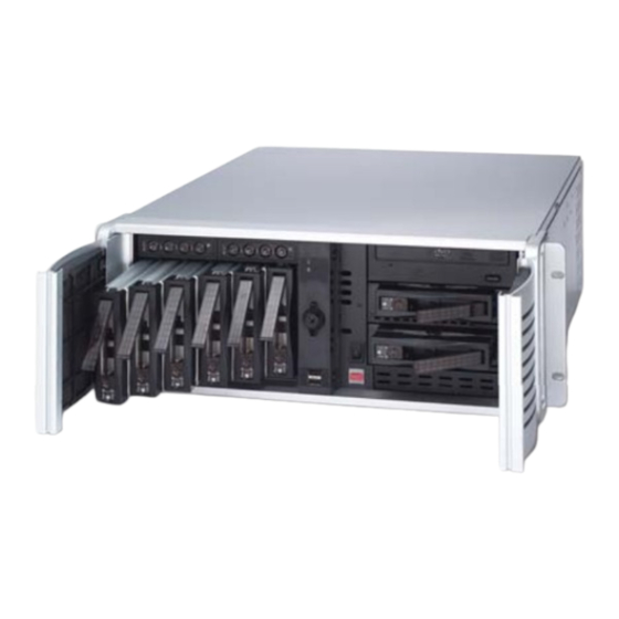
Page 3: Install The Hard Drive
. Ensure to format hard drives before they are usable. See 3.4 Formatting the Power Button Power LED and LED Hard Drive in GV-Hot Swap DVR System User's Manual. HDD Activity LED . To assign hot-swap drives as storage locations, see Adding the Hard Drive to Recording Path later in this guide. -
Page 4: Turn On The Power
Turn on the Power 20-Bay Models 1. Turn on the monitor. 1. Make sure the HDD Activity LED is off before you install the hard drive. 2. Slide the release latch to the right. The drawer handle pops up. Release Latch 2. - Page 5 Configuring an IP Address The purpose of configuring an IP address is to support the remote monitoring, 3. Turn on the main power switch on the front panel. control and configuration of the GV-Hot Swap DVR over a network connection. 8 / 4-Bay Models 1.
- Page 6 Exiting to Windows Returning to GV-Desktop The unit is protected by GV-Desktop that is limited to run the selected programs. If Click the Windows Start button, point to Programs, click GVCombo, and click you need to exit to Windows desktop, follow these steps. Key Lock Utility.
-
Page 7: Main Screen
Main Screen Adding Hot Swap Drive to Recording Path Click to call up I/O Control Panel Click to call up PTZ Control Panel Status indicators for remote applications Before recording, you need to add the formatted hard drive to the recording path. Date / Time / Storage Space Camera Name Note: The default recording path for the hot-swap drives starts from F:\... - Page 8 Choosing Recording Mode 5. In the MedianMan Tools window, if the hard drive is successfully added to store You can set each camera's recording mode individually for Motion Detection or data, its Status field should display “Standby”. Round-the-Clock. 1. Click on the main screen, point to General Setting, and select System Configure.
-
Page 9: Set Up A Recording Schedule
Changing Recording Resolution Set Up a Recording Schedule The default recording resolution is 320 x 240. You can set each camera's recording resolution individually. You can program recording to turn on and off at a specific time each day. 1. Click on the main screen, point to A/V Setting, and select Video Source. -
Page 10: Playback Video
Play Back Video Playback Controls You can play back video recorded during a particular date and time. 1. Click on the main screen, and select Video/Audio Log. Playback Scroll Audio on/off 2. Select the camera you wish to view. 3. Select a date folder from the date tree. 4. -
Page 11: Back Up Video Files
Back Up Video Files You can back up video files of the desired time to CD / DVD. 1. Insert the CD / DVD media into the drive. 2. Click on the main screen, and select Video/Audio Log. 3. Click on the functional panel. -
Page 12: Recovery Dvd
“The recovery process is finished. Please remove DVD and press “OK” to reboot” will appear. Manually remove the DVD and then click OK. Step 6 9F, No. 246, Sec. 1, Neihu Rd., Neihu District, Taipei, Taiwan Tel: +886-2-8797-8377 Fax: +886-2-8797-8335 dvrsystem@geovision.com.tw http://www.geovision.com.tw...
Need help?
Do you have a question about the GV-HOT SWAP DVR SYSTEM and is the answer not in the manual?
Questions and answers