Table of Contents
Advertisement
Quick Links
Download this manual
See also:
User Manual
Quick Start Guide
The Vision of Security
Thank you for purchasing GV-Tower System. This guide is designed to assist the new user in getting
immediate results from the GV-Tower System. For advanced information on how to use the GV-Tower
System, please refer to GV-Tower System User's Manual (GV-Desktop > Program button >
User Manual).
© 2015 GeoVision, Inc. All rights reserved.
All GeoVision Products are manufactured in Taiwan.
RoHS
2015/04
English
Tower-QG-C
Advertisement
Table of Contents

Related Manuals for GeoVision GV-Tower


Summary of Contents for GeoVision GV-Tower
-
Page 1: Quick Start Guide
The Vision of Security RoHS Thank you for purchasing GV-Tower System. This guide is designed to assist the new user in getting immediate results from the GV-Tower System. For advanced information on how to use the GV-Tower System, please refer to GV-Tower System User's Manual (GV-Desktop > Program button >... - Page 2 Every effort has been made to ensure that the information in this manual is accurate. GeoVision, Inc. makes no expressed or implied warranty of any kind and assumes no responsibility for errors or omissions. No liability is assumed for incidental or consequential damages arising from the use of the information or products contained herein.
-
Page 3: Table Of Contents
Contents Introduction................................. 2 Packing List................................2 1.1.1 GV-Tower DVR/NVR System .......................... 2 1.1.2 GV-Tower VMS System ........................... 3 Front View & Fear View ............................4 Basic Installation..............................6 Recommended Hard Drive ..........................8 Install the Hard Drive............................... 9 Turn On the Power ..............................11 Windows Setup Installation.......................... -
Page 4: Introduction
Introduction Welcome to the GV-Tower System Quick Start Guide. In the following sections, you will learn about the basic installations and configurations of the GV-Tower System User’s Manual (GV- Desktop > Program button > User Manual). 1.1 Packing List 1.1.1 GV-Tower DVR/NVR System •... -
Page 5: Gv-Tower Vms System
• GV-Tower VMS System x 1 • Key for Hard Disk Safety Lock x 2 • Hard Disk Drive Screw x 16 • GV-IR Remote Control x 1 • AC Power Cord x 1 • GV-Tower System Quick Start Guide x 1... -
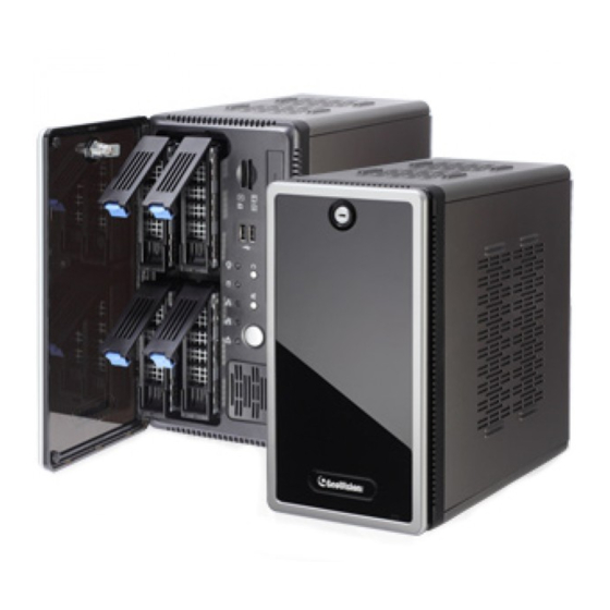
Page 6: Front View & Fear View
1.2 Front View & Fear View Front View No. Name Name HDD x 4 Not Functional Not Functional IR Receiver Not Functional Power Button Not Functional Not Functional Not Functional HDD Activity LED (Red) Reset Button Power LED (Blue) -
Page 7: Rear View
VGA Monitor Output Audio Line Out Port HDMI Port Audio Line In Port USB 2.0 Port x 2 Ethernet Port x 2 PS/2 Port (only for the keyboard) * Note: The feature marked with is for GV-Tower DVR System only. -
Page 8: Basic Installation
1.3 Basic Installation Here we use GV-Tower DVR System as the example. 1. There are two ways to connect the monitor to the GV-Tower DVR/NVR System Tower VMS System. • Using the VGA cable supplied by the monitor manufacturer, connect the VGA monitor. - Page 9 Using the IR Remote Control The GV-IR Remote Control provides easy control of the GV-Tower DVR/NVR System and GV-Tower VMS System. Its receiver is a built-in device. For details, see GV-IR Remote Control User’s Manual (GV-Desktop > Program button >...
-
Page 10: Recommended Hard Drive
1.4 Recommended Hard Drive For system efficiency, we recommend the following enterprise level hard disk drives. Avoid using desktop level or green HDD which may affect system efficiency. • WD RE series • Seagate Constellation ES.3 series • HGST Ultrastar series... -
Page 11: Install The Hard Drive
Install the Hard Drive The GV-Tower DVR/NVR System or GV-Tower VMS System uses SATA hard drives for video and audio data storage. Before recording, ensure to install your hard drives. Follow the below steps to install the hard drive. 1. Press the release latch. The drawer handle pops up. - Page 12 5. Secure the hard drive with the 4 screws, and make sure all screw heads flush with the surface. or GV-Tower 6. Put the drawer back in the drive bay of the GV-Tower DVR/NVR System VMS System , and push the latch until it locks.
-
Page 13: Turn On The Power
Turn On the Power 3.1 Windows Setup Installation The Windows setup is preparing your computer for first use. 1. After the Windows starts, the following screen pops up. Select your language and click Next. 2. Select your country or region, time and currency and keyboard layout. Then click Next. - Page 14 3. Type a user name for your account and then click Next to continue. 4. It is recommended that you create a password for your account and then click Next to continue. 5. Since no license terms are specified, the page is left blank intentionally. Select I accept the license terms and click Next.
- Page 15 6. You are suggested to select Ask me later to disable Windows automatic update. Selecting the other two options may generate temporary files and result in wasting the internal disk space. 7. Select your time zone, date and time and click Next. 8.
-
Page 16: Configuring The Ip Address
3.2 Configuring the IP Address GV-Tower DVR/NVR System and GV-Tower VMS System support remote monitoring, control and configuration over a network connection. The following default IP addresses will automatically be assigned. • Connection 1: 192.168.0.200 • Connection 2: 192.168.0.201 •... - Page 17 To change the above default IP addresses, follow the steps below. 1. On the GV-Desktop, click the Programs button, and select Control Panel. 2. Type the ID and password. The default ID and password are “0000”. The Control Panel window appears. 3.
- Page 18 5. Select Internet Protocol Version 4 (TCP/IPv4), and select Properties. 6. Select Use the following IP address and type the new IP information in the fields. Or select Obtain an IP address automatically to enable dynamic IP address. 7. Click OK to finish the setting.
-
Page 19: Exiting To Windows
3.3 Exiting to Windows GV-Tower DVR/NVR System and GV-Tower VMS System is protected by GV-Desktop that is limited to run the selected programs. If you need to exit to Windows desktop, follow these steps. 1. Exit the main screen to display the GV-Desktop screen. -
Page 20: Gv-Tower Dvr/Nvr System
GV-Tower DVR/NVR System 4.1 Main Screen No. Name Name Logout / Exit / Minimize Start/stop screen rotation Select screen divisions Access remote applications Select a camera for full screen Camera Name mode Start/stop recording Date / Time / Storage Space... -
Page 21: Adding Hot Swap Drive To Recording Path
Add for recording, and then select the storage group from the drop-down list. If a hard drive is not inserted, follow these steps: Insert a hot-swap hard drive or plug a portable hard drive to the GV-Tower NVR/DVR System. This dialog box appears. -
Page 22: Adding Ip Video Devices
4.1.2 Adding IP Video Devices The procedures for adding an IP camera, Video Server and Compact DVR may vary. The following instructions are the setup procedure for adding an IP camera in the system. 1. On the main screen, click the Configure button, select System Configure and click IP Camera Install. - Page 23 4. Select a camera brand and model from the Brand and Device drop-down lists respectively. This dialog box appears. 5. The options in the dialog box may vary depending on camera brands. • Dual Streams: Click the button to apply the default codec and resolution of the GV- IP camera.
-
Page 24: Renaming The Camera
8. The Status column now should display “Connected”. Click OK. For details, refer to Hybrid and NVR Solution, Chapter 2, GV-DVR User’s Manual on Software DVD (or GV-Desktop > Program button > User Manual). 4.1.3 Renaming the Camera Click on the main screen, click System Configure and select Camera Configure. In the Camera Name field, type a new name for the camera. -
Page 25: Choosing Recording Mode
4.1.4 Choosing Recording Mode You can set each camera's recording mode individually for Motion Detection, Round-the- Clock or Day-Night. Click on the main screen, click System Configure and select Camera Configure. From the Camera Name drop-down list, select one camera. In the Rec Control field, select Rec Video, and use the drop-down list to select Motion Detect, Round-the-Clock or Day-Night. -
Page 26: Changing Recording Resolution
4.1.5 Changing Recording Resolution You can set each camera's recording resolution individually. Click on the main screen, click A/V Setting and select Video Source. Select the desired video resolution from the drop-down list, and click OK. Click on the main screen, click System Configure and select Camera Configure. From the Camera Name drop-down list, select one camera. -
Page 27: Set Up A Recording Schedule
4.2 Set Up a Recording Schedule You can program recording to turn on and off at a specific time each day. Click on the main screen, and select Schedule Edit. Select or enter the Start and End time of the schedule. Select day(s). -
Page 28: Play Back Video
4.3 Play Back Video You can play back video recorded during a particular date and time. Click on the main screen, and select Video/Audio Log. Select the camera you wish to view. Select a date folder from the date tree. Select a time from the Video Events list. - Page 29 Playback Controls 9 10 11 No. Name Name Rewind to Beginning Speed up/down Frame-by-Frame Reverse Zoom in/out Rewind A to B Playback Stop Frame-by-Frame / Real Time Playback Play Playback Scroll Frame-by-Frame Forward Audio on/off Forward to End Using the Zoom •...
-
Page 30: Back Up Video Files
4.4 Back Up Video Files You can back up video files of the desired time to CD / DVD. Insert the CD / DVD media into the drive. Click on the main screen, and select Video/Audio Log. Click on the functional panel. Select CD Using OS-Burning to burn files with the inbuilt software of Windows. - Page 31 Playback Controls Open the backup folder, run EZViewLog500.exe, and then follow the instructions in the Play Back Video section.
-
Page 32: Gv-Tower Vms System
Brings up these options when Home is selected: • Monitor: Start / Stop monitoring, I/O monitoring and schedule monitoring • Network: Enable Webcam Server and connection to other GeoVision software. • Tools: Show / hide volume indicator and set up Object Index. -
Page 33: Adding Hot Swap Drive To Recording Path
5.1.1 Adding Hot Swap Drive to Recording Path Before recording, you need to add a formatted hard drive to the recording path. Note: The default recording path for the hot-swap drives starts from D:\ On the GV-VMS, click Home , select Toolbar , select Configure , select System Configure, and click Record Setting. - Page 34 3. To add a hard drive to the recording path, follow these steps: A. To add a new folder in the first storage group, click the Add button on the right pane and select a folder. Only 1 folder can be assigned as storage folder for each partition (e.g.
-
Page 35: Adding Ip Cameras To Gv-Vms
5.1.2 Adding IP Cameras to GV-VMS The Automatic Setup dialog box appears automatically. 1. Click Automatic Setup to see the list of IP cameras detected on the LAN. 2. The default login information for cameras is admin / admin. Double-click the camera to type different ID and password in the dialog box below if needed. - Page 36 3. Make sure the cameras you want to add are selected and click Apply. The cameras added are now listed in the IP Device List. Status icons available: Connected The camera is connected. Connecting GV-VMS is trying to connect to the camera. Connection Failed Unable to connect to the camera.
-
Page 37: Configuring Camera Settings
5.2 Configuring Camera Settings After the cameras are added, you can configure their settings, such as video, audio and other general settings. Click the Setup button of an active camera in the IP Device List (Home > Toolbar > Configure >... -
Page 38: Play Back Recorded Videos
5.3 Play Back Recorded Videos To access recorded videos, click the ViewLog icon in the top-right corner. Open the Content List by clicking Toolbar and selecting Content List Click Layout in the Content List, click the Add button , and select Add Layout to create a new layout or select Import from Live to import existing layouts from live view. - Page 39 Click on the timeline to select a time with video recordings. You can scroll the mouse to zoom in and out on the timeline. Use the playback control buttons to play back recordings. Place the cursor on the buttons to see the name of the function.
-
Page 40: Back Up Recorded Videos
To include the ViewLog player to the backed up files, select Include Player at the bottom-right of the dialog box. If no player is selected, you can only play the recordings using computer installed with GV-VMS or GeoVision video code. -
Page 41: Restore System
On the GV-Desktop, click the Program List button and select Recovery. The system will run this command by itself. Restart the GV-Tower DVR/NVR System or GV-Tower VMS System. Press F11 button several times to avoid accessing the GV-Tower DVR/NVR System or GV-Tower VMS System. - Page 42 When the below screen appears, click the Recovery button. to restart the Windows. For how to change video standard after recovery, see section 3.12.2 in GV-Tower System User’s Manual (GV-Desktop > Program button > User Manual).
Need help?
Do you have a question about the GV-Tower and is the answer not in the manual?
Questions and answers