Leibinger JET2NEO Manual
Hide thumbs
Also See for JET2NEO:
- Manual (64 pages) ,
- Instruction manual and quick start manual (134 pages)
Table of Contents
Advertisement
Quick Links
Advertisement
Table of Contents

Related Manuals for Leibinger JET2NEO


Summary of Contents for Leibinger JET2NEO
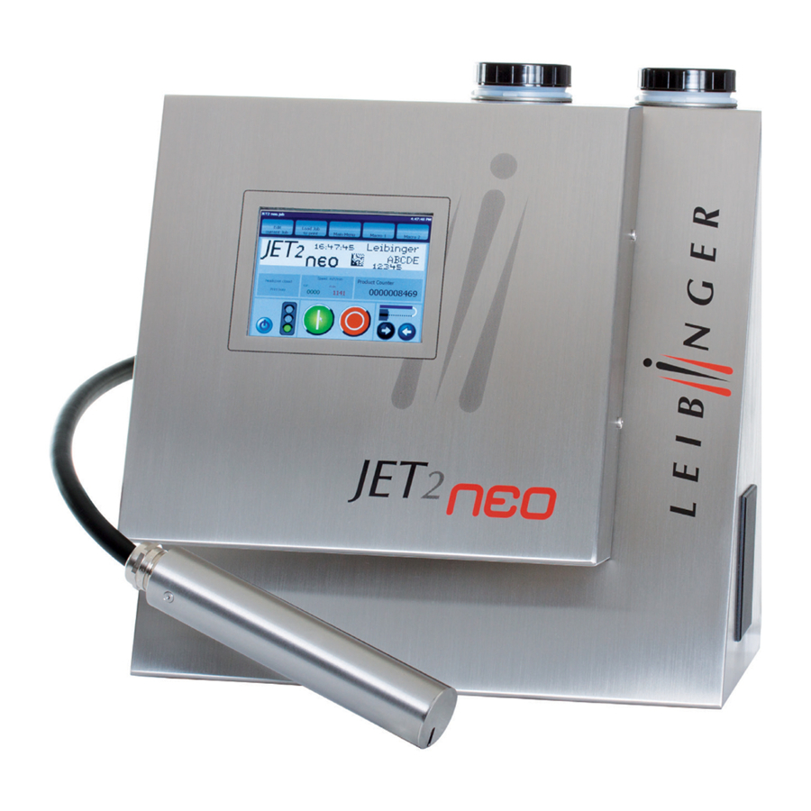
- Page 1 Manual LEIBINGER JET2NEO Release 1.12en...
-
Page 3: Table Of Contents
Group 1 Table of contents Page 1 1.1 Table of contents 1.1 Table of contents ......................1 1.2 Group directory ......................11 1.3 Publisher ........................12 1.4 Introduction ........................14 1.5 Document information ....................15 1.6 Guarantee ........................15 2. Safety ..........................16 2.1 Dangers ........................ - Page 4 Page 2 Table of contents Group 1 5.1 Transport, storage, shipping ..................30 5.2 Mounting ........................30 5.3 Installation ........................32 5.3.1 Mains supply ......................32 5.3.2 Grounding (Potential equalization) ............... 32 5.3.3 Explosion protection ..................... 34 5.3.4 Print head ......................34 5.4 Starting .........................
- Page 5 Group 1 Table of contents Page 3 6.5.3 Switch on device ....................64 6.5.3.1 Switching on without password protection ............ 64 6.5.3.2 Switching on with password protection ............65 6.5.4 Reset product counter ..................67 6.5.5 Change product counter ..................69 6.5.6 Product counter –...
- Page 6 Page 4 Table of contents Group 1 7.2.2.3 Login/Logout ....................103 7.2.2.3.1 Login user and carry out user change ........... 103 7.2.2.3.2 Logout user .................... 104 7.2.2.4 Product counter ................... 106 7.2.2.4.1 Product counter settings ................ 107 7.2.2.4.2 Stop after x products (Pre-defined print stop) ........109 7.2.2.5 Macro generator ..................
- Page 7 Group 1 Table of contents Page 5 7.2.3.6 I/O-settings ....................142 7.2.3.6.1 Inputs ..................... 143 7.2.3.6.2 Outputs ....................144 7.2.4 Functional area Service ..................145 7.2.4.1 Info ......................146 7.2.4.1.1 Save info file ..................147 7.2.4.2 I/O Test (Signaltest) ..................148 7.2.4.3 Data logging (Log File) ................
- Page 8 Page 6 Table of contents Group 1 8.5.1.1 Print height ....................189 8.5.1.2 Font width (Stroke distance) ................ 189 8.5.1.3 Orientation ....................190 8.5.1.4 Printing mode ....................191 8.5.2 PrintGo-Parameter ..................... 193 8.5.2.1 Functional area PrintGo 1 ................193 8.5.2.1.1 PrintGo-delay ..................194 8.5.2.1.2 PrintGo-distance ..................
- Page 9 Group 1 Table of contents Page 7 8.6.1.3.2 Character space (ICG) ................219 8.6.1.3.3 Bar height ....................219 8.6.1.3.4 Styles (Selection of the barcode styles) ..........219 8.6.1.3.5 Default settings of styles (Changing of the barcode style sett.) ..... 219 8.6.1.4 Integration of printing elements into barcodes ..........
- Page 10 12.2.2.3 Jobselect Input ..................277 12.2.2.4 Inputs ......................278 12.2.4.5 ON Input ....................278 12.3 Drawings ........................279 12.3.1 Print head ......................279 12.3.2 Cabinet JET2neo ..................... 280 List of keywords/Index ....................... 281 List of illustrations ......................288 Release R1.12 en JET2 neo...
- Page 11 Group 1 Table of contents Page 9 JET2 neo Release R1.12 en...
-
Page 13: Group Directory
Group 1 Group directory Page 11 1.2 Group directory The group directory serves as a guide through the device manual at hand to be able to find specific subject areas quickly. Group Directory Page Overview ......................1 Table of contents ................... 1 Group directory ..................... -
Page 14: Publisher
Page 12 Publisher Group 1 1.3 Publisher For questions regarding the operation and running of the LEIBINGER JET2neo as well as in service case please contact the listed dealer address. Dealer address Paul Leibinger GmbH & Co. KG Marking & Coding Systems Daimlerstraße 14... - Page 15 Texts, illustrations and technical drawings have been compiled with the greatest of care. Nevertheless errors cannot be excluded. Consequently no guarantee can be assumed for the correctness of the content of this manual and no claims can be asserted against Paul Leibinger GmbH & Co. KG.
-
Page 16: Introduction
It is only through the use of inks and solvents from Paul Leibinger GmbH & Co. KG that optimum operating characteristics can be achieved. Should other inks and solvents be used all guarantee claims will expire. -
Page 17: Document Information
At this point we wish to make explicit reference to the fact that it is only when using solvent and ink from Paul Leibinger GmbH & Co. KG that the optimum operating characteristics can be achieved. In the event of use of other inks and solvents all guarantee entitlements shall cease to apply. -
Page 18: Safety
the health of the operating staff the high performance printer JET2neo and other real assets of the plant operator the efficient operation of the high performance printer... - Page 19 Failure to observe this instruction can lead to material damage, the loss of guarantee and to injury! Indicates service activities! This work may only be carried out by trained personnel or Leibinger- service technicians! JET2 neo Release R1.12 en...
-
Page 20: Intended Use
2.3 Intended use The high performance printer JET2neo serves exclusively the contact-free marking, inscribing and coding of surfaces using the continuous ink jet process. The high performance printer can be used on the most varying materials (e.g. metal, synthetic material, glass, paper, wood, pressed materials, rubber etc.) with both, smooth as well as... -
Page 21: Safety Sticker
Group 2 Safety Page 19 2.4 Safety sticker Figure 1 Safety sticker JET2 neo Release R1.12 en... -
Page 22: Operating Staff
Only trained personnel must operate the device. The personnel must have appropriate training to enable them to be able to operate the JET2neo high performance printer professionally. Within the working area of the LEIBINGER JET2neo device the operator is responsible with regard to third parties. -
Page 23: Safety Measures At The Place Of Installation
Prior to assembly the place of setting up must be cleaned of dirt and contamination (residue of lubricants etc.). The working place surroundings should be kept clean at all times in order to ensure unrestricted access to the LEIBINGER JET2neo device. JET2 neo Release R1.12 en... -
Page 24: Dangers Through Consumables
Page 22 Safety Group 2 2.10 Dangers through consumables Inks are coloured liquids on a solvent basis. The safety instructions on the containers of the consumables as well as the instructions in the group Accident prevention must be especially adhered to in order to exclude dangers for persons and the surroundings. Further instructions can be found in the Safety Data Sheets. -
Page 25: Accident Prevention
Group 3 Accident prevention Page 23 3. Accident prevention The following presentation shows the measures in the event of an accident with ink and solvent with the danger marking, slightly ignitable irritates the eyes and the respiratory organs. 3.1 Storage and handling (normal use) GENERAL These products must only used at points that are free from open... -
Page 26: First Aid Measures
Page 24 Accident prevention Group 3 3.2 First aid measures EYES Contact lenses must be removed. Rinse thoroughly with pure, fresh water for at least 10 minutes, keep eyelids spread and call a doctor. SKIN Remove contaminated clothes. Wash skin thoroughly with soap and water or with a branded skin cleansing agent. -
Page 27: Measures In The Event Of Accidental Release (Spillage)
Group 3 Accident prevention Page 25 3.4 Measures in the event of accidental release (spillage) PRECAUTIONARY Switch off sources of ignition and ventilate room. Keep personnel MEASURES that are not absolutely necessary away. Do not inhale any vapour. Observe the protective measures listed. ENVIRONMENTAL DO NOT allow to enter waste water channels or waters. -
Page 28: Technical Data
Group 4 Technical data Page 26 4. Technical data 4.1 Housings, dimensions, weights Cabinet : Stainless steel Width 400 mm, depth 295 mm, height 430 mm Weight: 17 kg Print head: Stainless steel cabinet Length (total) 212 mm, diameter 43 mm Length of the print head lead 3 m Weight: 1,5 kg Any fitting position, also for overhead conveyor applications... -
Page 29: Electrical Connection Values
Group 4 Technical data Page 27 4.2 Electrical connection values Input voltage (voltage range): 100 - 240 V AC ,50-60 Hz Current consumption: max. 0,33 A at 100 V AC max. 0,20 A at 240 V AC Power consumption: max. 35 VA at 100 V AC max. -
Page 30: Performance Parameter
Page 28 Technical data Group 4 4.5 Performance parameter Printing capacity: Character height: approx. min.: 1,2 mm max.:11 mm Depending on font, distance of head, nozzle diameter, ink, product surface and type of print head Up to 3200 characters/sec. Printing speed: Up to 6,6 m/sec (10 cpi) 4.6 Fonts... -
Page 31: Function
Group 4 Technical data Page 29 4.9 Function Full automatic function by: The automatic nozzle seal guarantees that the print head is ready to print immediately after starting. Automatic, electronic drop control for compensation of changing ambient- and operating temperatures ... -
Page 32: Transport/Start Up
In order to avoid damage during transport the following instructions must be observed. The LEIBINGER JET2neo must only be transported in a standing position. It is packed in a cardboard box with special polystyrene inserts for safe dispatch during delivery. Transport of the device must only be made in this packing in order to avoid damage. -
Page 33: Transport/Start Up
Movable underframe for JET2neo Ground plate 1 – Movable underframe 2 – Adapter plate JET2neo (2x) 3 – Printer JET2neo For this it is expedient to place the device on a device support. Remark: Device carrier set is available as an accessory. -
Page 34: Installation
The device does not have a mains switch and should be only connected to an easy accessible socket close to the installation location! The LEIBINGER JET2neo should be connected to AC voltage 100-240 V AC, 50-60 Hz with an appropriate plug. The socket should be provided with a clear designation (e.g.: JET2neo). -
Page 35: Figure 6 - Grounding Schematic And Grounding Point
Group 5 Transport/Start up Page 33 Please note, that the grounding point (6) is hidden behind the round grounding-symbol-label (7) on the lower left hand side of the cabinet of the printer. Figure 6 Grounding schematic and grounding point Grounding schematic ground / earth (earth) 1 –... -
Page 36: Explosion Protection
Page 34 Transport/Start up Group 5 The printer must be always be switched off and the mains plug must be always unplugged if you plug and/or unplug any connectors! 5.3.3 Explosion protection The device has to be integrated in the lightning protection concept of the operator! Further more protection measures regarding electrostatics have to be made! 5.3.4 Print head Inflammable (Risk of fire)! -
Page 37: Figure 7 - Print Head Installation (Example)
Group 5 Transport/Start up Page 35 Figure 7 Print head installation (Example) = Conveying direction 1 – Product 4 – Sensor 6 – Umbilical (Hose connection) 2 – Conveyor belt 5 – Print head 7 – Print head adapter 3 – Encoder (accessories) The print head should be attached vibration-free. -
Page 38: Starting
Page 36 Transport/Start up Group 5 Installation of print head During an installation of a device in a production line, the operating staff should be not endangered. Due to moving products under the print head danger of bruising and shearing can be caused. The regulations of the machinery directives should be observed! 5.4 Starting (Commissioning) -
Page 39: Figure 8 - Remove Transportation Protection
Group 5 Transport/Start up Page 37 Figure 8 Remove transportation protection Attention! Do not remove the cable tie! 1 – Back cover (Hydraulic cabinet) 3 – Main filter (Do not remove the cable tie) 2 – Fixing screws (8x) JET2 neo Release R1.12 en... -
Page 40: Fill Reservoir Tank
Before filling the device with the consumables, measures for the electrostatic discharge have to be made! The operator can carry out a discharge either by the direct touching of the JET2neo cabinet or by standing with the appropriate ESD-shoes on an grounded surface! - Page 41 Group 5 Transport/Start up Page 39 Proceeding: Inflammable (Risk of fire)! Combustible gases and liquids cause serious burns. Sources of ignition must be kept away from the device! Attention! Before the filling process a static discharge has to be carried out necessarily! For this you have to touch the cabinet of the printer directly or you have to stand with ESD-shoes on an grounded surface before the filling or during the process!
-
Page 42: Carry Out Fill Up Routine
Page 40 Transport/Start up Group 5 5.4.3 Carry out fill up routine (Step 3) After filling the consumables (ink and solvent) you have to carry out the fill up routine. Proceeding: Figure 9 Fill up routine (Step 1) Message during the routine 1 –... - Page 43 Group 5 Transport/Start up Page 41 Turn on the printer. For this touch the dark touch-display (1) at any position for approx. 2 sec. The device turns on and the message<Initialization> (2) is displayed. Wait until the initialization is finished. After this process the message <Emergency Shutdown> (3) is displayed.
-
Page 44: Figure 10 - Filling Routine (Step 2)
Page 42 Transport/Start up Group 5 Figure 10 Fill up routine (Step 2) 9 – Message <Fill up routine finished> 13 – Button <OK ()> 10 – Button <OK ()> 14 – Message <Bleeding> 11 – Button <Close> 15 – Button <Cancel> 12 –... -
Page 45: Interfaces
Group 5 Transport/Start up Page 43 5.5 Interfaces The following interfaces are available on the rear side of the electronics cabinet. Figure 11 Interfaces 1 – Electronic cabinet 5 – Interface X4 – digital inputs 2 – Interface X1 – Encoder 6 –... -
Page 46: Interface X1 (Encoder)
Page 44 Transport/Start up Group 5 5.5.1 Interface X1 (Encoder) 5.5.1.1 Description and configuration The interface “X1” provides the connection of a shaft encoder. Due to the input for which you can set the software individually, the encoders can be connected according to different norms without an additional converter. -
Page 47: Mechanical Installation
Regarding the software you can select additionally if the positive edge or the negative edge should be used for the release of the print out. Note: To inform the JET2neo when a print text should be printed, you require a so-called Print-Go signal. - Page 48 Page 46 Transport/Start up Group 5 Basic data/Recommended working conditions: Signal Parameter Value PrintGo Input level High 15 up to 30V Input level Low -3,5V up to 3,5V (or high resistance) PNP-sensors Minimum pulse duration 100µS Input resistance 6,8 kOhm PrintGo Input level High 20 up to 28V (or high resistance)
-
Page 49: Interface X3 (Outputs)
Overcurrent- and excess temperature –proof The function allocations of the outputs are carried out with the software of the JET2neo in the menu Main menu Settings I/O-settings Outputs. You will find a circuit diagram of the interface in the appendix of this... -
Page 50: Interface X4 (Inputs)
Page 48 Transport/Start up Group 5 5.5.4 Interface X4 (Inputs) 13 inputs for special functions are available whereof the connections of 3 inputs can be freely selected. Plug assignment: Pin connection: Pin Designation Pin Designation +Reset Counter +24V +Increment Counter GND Reset Counter / Increment Counter +Jobselect 0... -
Page 51: Usb-Connection
Mirrored horizontally 200ms Gauger synchronization signal 200ms The function allocations of the inputs 1 up to 3 happen by the software of JET2neo menu Main menu Settings I/O settings Inputs. You will find a circuit diagram of the interface in the appendix of this manual! 5.5.5 USB-Connection... -
Page 52: Operation
6. Operation 6.1 Construction/Structure of the device The high-performance LEIBINGER JET2neo is manufactured of a solid two parts stainless steel cabinet. Due to the two parts construction you will get a thermal separation between the hydraulic- and electronic section. The device consists of the following main components. -
Page 53: Functional Principle
6.2 Functional principle 6.2.1 Method of working The JET2neo works in accordance with the continuous ink jet process. In this a constant ink jet is emitted from a jet nozzle which is broken down into a series of equal size drops under the influence of mechanical oscillations. -
Page 54: Drop Charging
Operation – Elements and procedures Page 52 Group 6 6.2.3 Drop charging In order to be able to charge the drops it is necessary for the ink to have electrical conductivity. This is possible through the use of specific salts that dissociate in the solvent used. -
Page 55: Summary Of The Individual Procedures
Operation – Elements and procedures Group 6 Page 53 6.2.6 Summary of the individual procedures Figure 13 Creation of a character Character height created by drop deflection Character „E“ build with a 7 x 5 matrix Rel. movement direction of the description area Drop brake-off point Gutter... -
Page 56: Example Of Use
Operation – Elements and procedures Page 54 Group 6 6.2.7 Example of use Figure 14 Example of use = Direction of conveyance 1 – Product 3 – Encoder 5 – Print head 2 – Conveyor belt 4 – Sensor 6.3 Safety instructions Inflammable (Risk of fire)! Combustible gases and liquids cause serious burns. -
Page 57: Essential Operating- And Information Elements
Operation – Elements and procedures Group 6 Page 55 6.4 Essential operating- and information elements This chapter describes the essential operating- and information elements of the LEIBINGER JET2neo basic menu. Figure 15 Basic menu (Construction) 1 – Title bar 7 – Status field <Product counter>... -
Page 58: Figure 16 Menu Bar
Scroll bar of the display area (3): You can view the whole display area if necessary by using the scroll bar. Menu bar (4): The appropriate menus or specific functions of the JET2neo can be opened with the buttons in the menu bar. The following buttons are available:... - Page 59 Operation – Elements and procedures Group 6 Page 57 If a button appears in grey, it is not available at the moment. Example: available not available The two <Macro…> buttons can be freely defined to call frequently used menus or functions directly for example.
-
Page 60: Figure 17 - Status Field
Operation – Elements and procedures Page 58 Group 6 Figure 17 Status field <Product counter> You will find further information also in the chapters Reset production counter and Change production counter as well as in the chapter Pre- defined print stop! ... - Page 61 Group 6 Page 59 Filling level indicator (9): The JET2neo was equipped with a filling level indicator for ink and solvent. Filling level ink Filling level solvent The indicators are located in the lower, left corner of the main window.
- Page 62 Operation – Elements and procedures Page 60 Group 6 Button <Off> (10): With this button you can switch off the device. You will find further information also in the Chapter Switch off device! Button <Switch On/OFF VNC server> (11): The VNC Server is activated by a button on main window.
-
Page 63: Number Blocks
Operation – Elements and procedures Group 6 Page 61 6.4.1 Number blocks Figure 19 Structure of the number blocks (Example view) 1 – Title bar 4 – Button <> 7 – Button <Backspace> 2 – Display 5 – Button <> 8 –... -
Page 64: Keyboard Fields
Operation – Elements and procedures Page 62 Group 6 6.4.2 Keyboard fields Figure 20 Structure of keyboard field Capital letters Small letters Special characters short longer selected touch press short longer touch press 1 – Button <Return > 3 – Button <Shift/Caps Lock> 2 –... -
Page 65: Basic Operating Processes
For this procedure the boot-manager is started. The progress of the initialization is shown by a bar. After finishing the process the device is switched to the standby-mode (monitor is dark) and the JET2neo is now ready to switch on by pressing the touch screen. -
Page 66: Switch On Device
Operation – Elements and procedures Page 64 Group 6 6.5.3 Switch on device 6.5.3.1 Switching on without password protection Proceeding: Touch the dark Touch-Display (1) at any point. Period of touching approx. 2 sec.. The devices turns on and the message <Initialization> (2) is displayed. ... -
Page 67: Switching On With Password Protection
Operation – Elements and procedures Group 6 Page 65 At the end of the bleeding process or after cancelling the process, the basic menu (5) opens. Note: For starting the device the job which has been used at last will be loaded automatically. -
Page 68: Figure 23 - Switch-On Procedure With Password Protec
Operation – Elements and procedures Page 66 Group 6 Figure 23 Switch-on procedure with password protection Release R1.12 en JET2 neo... -
Page 69: Reset Product Counter
Operation – Elements and procedures Group 6 Page 67 1 – TFT-Touch-Display 8 – Button <Login> 2 – Message <Initialization> 9 – Window <Password query> 3 – Message <Bleeding> 10 – Input field <Password> 4 – Button <Cancel> 11 – Keyboard field 5 –... - Page 70 Operation – Elements and procedures Page 68 Group 6 Proceeding: Press on the status field <Product counter> (1). The menu <Product counter> (2) is faded in. As standard the register card <Counter> (3) is activated and the current value of the counter appears in the display „Product counter“...
-
Page 71: Change Product Counter
Operation – Elements and procedures Group 6 Page 69 6.5.5 Change product counter (Change value) Figure 25 Change product counter (change value) 1 – Status field <Product counter> 5 – Number block <Product counter> 2 – Menu <Product counter> 6 – +/- buttons 3 –... -
Page 72: Product Counter - Pre-Defined Print Stop
Operation – Elements and procedures Page 70 Group 6 Proceeding: Press on the status field <Product counter> (1). The menu <Product counter> (2) is faded in. As standard the register card <Counter> (3) is activated and the current value of the counter appears in the display „Product counter“... -
Page 73: Switch Off Device
Operation – Elements and procedures Group 6 Page 71 6.5.7 Switch off device Figure 26 Switch-off procedure Message „Carry out print stop“ 1 – Button <Off> 4 – Button <No> 2 – Message <Safety query> 5 – Message <Shutdown> 3 – Button <Yes> 6 –... -
Page 74: Menu Layout
Operation – Elements and procedures Page 72 Group 6 Proceeding: Press the button <Off> (1). A safety query (2), if the printer should be really switched off is faded in. Confirm the shut down of the device by pressing the button <Yes> (3) or cancel the process with the button <No>... -
Page 75: Figure 28 - Menu Layout (Pop-Up Window)
Operation – Elements and procedures Group 6 Page 73 Display of functions: If a function (menu item) is displayed blue, it is available. If a function is displayed grey, it is not available at the moment If a function is activated or currently being performed, the button is disabled (negative) during the process. -
Page 76: Other Settings And Functions
Operation – Elements and procedures Page 74 Group 6 Control elements: Serve for saving settings or exiting menus. The following commands are assigned to the elements depending on the menu or function: Control elements Assignment/Occupancy (Buttons) Cancel Close Overtake Carry out OK/Yes... -
Page 77: Interval Operation (Integrated Clock Timer)
The device turns on automatically irrespectively of the ambient conditions! The integrated interval function activates the LEIBINGER JET2neo automatically in the on-state according to the times which have been set under the register card <Interval> (“Main menu Settings Basic settings Interval“). -
Page 78: Data Entry/Programming
7. Data entry/Programming 7.1 General Data which should be printed by the LEIBINGER JET2neo can be entered, called, changed and saved with several input devices, e.g. TFT-Touch display, mouse etc. Further more the LEIBINGER JET2neo can also carry out several functions (e.g. job selection) by the control with digital signals (e.g. -
Page 79: Functional Area Job
Group 7 Data entry/Programming Page 77 7.2.1 Functional area Job In the functional area <Job> following options are available: Load job to print Create new job Edit current job Reset all job counters Open job to edit ... -
Page 80: Edit Current Job
Page 78 Data entry/Programming Group 7 Figure 32 Create a new job 1 – Button <Create new job> 2 – Menu <Job editor> You will find further information regarding the operation of the job editor in the group Job editor. 7.2.1.2 Edit current job With the option <Edit current job>... -
Page 81: Figure 33 Open Job To Edit
Group 7 Data entry/Programming Page 79 Press the button <OK ()> (9) to take over the selected job or press the button <Cancel> (8) to cancel the process. The menu <Jobeditor> (10) opens to change the printing data. The name of the opened job is displayed in the title bar of the editor. -
Page 82: Create A New Job List
Page 80 Data entry/Programming Group 7 7.2.1.4 Create a new job list (Extern job selection) Job lists provide the possibility of combining several print jobs in one print list. Each print job on the list has its own address. The addressing happens through the respective digital inputs on interface X4. - Page 83 Group 7 Data entry/Programming Page 81 All settings in this dialog box will overwrite respective settings of the single print jobs on the job list. So for instance the settings on the <PrintGo page 2> tab are valid for all print jobs on the job list.
- Page 84 Page 82 Data entry/Programming Group 7 Basic rules for the job list type <Extern job selection>: Each print job is managed separately. Each print job needs a <PrintGo> signal to be printed. If a single print job of the <External Job> job list has to be edited, this has to be carried out with the job editor.
- Page 85 Group 7 Data entry/Programming Page 83 7.2.1.5 Load job to print An already saved job or job list can be loaded directly for printing with the <Load job to print> button. The job or the job list is selected in a <Open file> dialog box. Open job for printing Open job list for printing By default, the file list (1) is filtered for print...
- Page 86 Page 84 Data entry/Programming Group 7 Open job for editing Open job list for editing It is possible to open the currently loaded It is possible to open the currently loaded print job in the job editor directly from the job list in the job list editor directly from the main window (1).
-
Page 87: Reset All Job Counters
Group 7 Data entry/Programming Page 85 7.2.1.6 Reset all job counters With this function, all existing job counters in the current loaded job can be reset. Proceeding: Press the option <Reset all job counters> (1). A safety query (2), if all job counters have been reset is faded in. ... -
Page 88: Save Counter States
Page 86 Data entry/Programming Group 7 7.2.1.7 Save counter states For leaving a job, the counter status of integrated job counters are normally not saved, that means for calling this job again, the counter states are 0 respectively set to the predefined start values. -
Page 89: Functional Area Extra
Group 7 Data entry/Programming Page 87 7.2.2 Functional area Extra (Additional functions) In the functional area <Extra> following options are available: Logout Graphic-Editor Explorer Production counter settings Macro generator Direct printstart Delete extern text memory Figure 36 Functional area „Extra“... -
Page 90: Figure 37 - Graphic Editor (Structure And Call Up)
Page 88 Data entry/Programming Group 7 Further information about the organization, character, editing and viewing tools of the Graphic Editor can be found in the following chapters! Figure 37 Graphic editor (Structure and call up) 1 – Button <Graphic editor> 7 –... -
Page 91: Organization Tools
Group 7 Data entry/Programming Page 89 7.2.2.1.1 Organization tools With the buttons in the menu bar you can select the organization tools of the editor. Figure 38 Graphic editor (Organization tools) 1 – Organization tool <New> 3 – Organization tool <Save> 2 –... -
Page 92: Drawing Tools
Page 90 Data entry/Programming Group 7 7.2.2.1.2 Drawing tools Figure 39 Graphic editor (Drawing tools) 1 – drawing tool <Dot> selected 2 – drawing tool <Line> drawing tool 3 – drawing tool <Rectangle> 4 – drawing tool <Ellipse> 5 – drawing tool <Selection> 6 –... -
Page 93: Edit Tools
Group 7 Data entry/Programming Page 91 7.2.2.1.3 Edit tools With the icons (direct buttons) you can select the several edit tools. Note: The function of the tools corresponds to the Windows™-functions. Figure 40 Graphic editor (Edit tools) 1 – Edit tool <Cut> 4 –... -
Page 94: Load An Existing Graphic
Page 92 Data entry/Programming Group 7 7.2.2.1.5 Load an existing graphic With the button <Open> With the option <Open> you can open an existing graphic for processing. For selection of a graphic the window „Load graphic“ opens. Figure 42 Graphic editor (Load existing graphic) 1 –... -
Page 95: Save Graphic
Group 7 Data entry/Programming Page 93 7.2.2.1.6 Save graphic With the button <Save> an open graphic is saved under the current name or a new created graphic is saved under a new name. Attention! If the graphic is saved under an existing filename, no safety query is generated. - Page 96 Page 94 Data entry/Programming Group 7 1. Save an open existing graphic: Proceeding: Press the button <Save> (1) in the menu bar of the editor. The graphic will be saved under the existing filename. 2. Save a newly created graphic: Proceeding: ...
-
Page 97: Create And Process Graphic Elements
Group 7 Data entry/Programming Page 95 7.2.2.1.7 Create and process graphic elements 1. Creation of a graphic element: (Example.:A rectangle should be created) Proceeding: Press on the drawing tool <Rectangle> (1). Click in the grid of the input field on the requested start point (2). ... - Page 98 Page 96 Data entry/Programming Group 7 2. Deletion of a graphic element or graphic segment: (Example: A rectangle should be interrupted and a line should be deleted) Proceeding: Press on the drawing tool <Selection> (1). Click in the grid of the input field on an empty point close to the line which should be deleted.
-
Page 99: Figure 45 - Graphic Editor (Delete Graphic Elements)
Group 7 Data entry/Programming Page 97 Figure 45 Graphic editor (Delete graphic elements) Areas (elements) to delete 1 – Drawing tool <Selection> 6 – Edit tool <Delete> 2 – Start point (catch frame) 7 – Drawing tool <Selection> 3 – Display <Coordinates> 8 –... -
Page 100: Set Editor Size
Page 98 Data entry/Programming Group 7 7.2.2.1.8 Set editor size With the button <Settings> you can set the editor size (width and height of the drawing area). Figure 46 Graphic editor (Set editor size) Editor size 1 – Button <Settings> 5 –... -
Page 101: Explorer
The explorer administrates the data of the LEIBINGER JET2neo. As the explorer of the PCs, the explorer in the JET2neo allows the deletion of data as well as the free saving and loading of data on different media (e.g. USB-stick) or of the internal memory. Selection window and filter functions allow a clear and easy to operate data management. -
Page 102: Menu Structure
Buttons <Tools> (1): With the buttons you can select the several tools of the explorer. Selection window <Internal memory> (2): In the selection window the data or the filtered data of the internal memory of the JET2neo are displayed. Selection window <USB-Stick> (3): In the selection window the data or the filtered data of the external data carrier are displayed. -
Page 103: Explorer Tools
Group 7 Data entry/Programming Page 101 With the button <Clone internal memory> (5) all data of the JET2neo are duplicated to an external data carrier. The button <Close> (6) closes the explorer. 7.2.2.2.3 Explorer tools Figure 49 Explorer (Tools) 1 –... -
Page 104: Delete Jobs
Page 102 Data entry/Programming Group 7 7.2.2.2.4 Delete jobs A job can only be deleted in the explorer! (Example: The job „Test 3“ should be deleted in the internal memory.) Figure 50 Explorer (Delete job) 1 – Slection window <Internal memory> 5 –... -
Page 105: Login/Logout
Group 7 Data entry/Programming Page 103 7.2.2.3 Login/Logout With the button <Login> the user can log in when starting the device or a new user can log in during operation to perform functions for which the originally logged in operator is not authorized for example. -
Page 106: Logout User
Page 104 Data entry/Programming Group 7 Proceeding: Press the button <Login> (1). The window <Password query> (2) is called up. Click into the input field <Password> (3) of the window. A keyboard field (4) opens for entry. ... -
Page 107: Figure 52 Login (Logout User)
Group 7 Data entry/Programming Page 105 After logging-out of the user, only the function <Login> is available. Figure 52 Login (Logout user) 5 – Button <Return > 1 – Button <Logout> 2 – Window <Password query> 6 – Input field <Password> 3 –... -
Page 108: Product Counter
Page 106 Data entry/Programming Group 7 7.2.2.4 Product counter With the button <Product counter settings> (1) the menu „Product counter “ (2) opens. This menu serves the setting of the product counter a pre-defined print stop The selection of a functional area happens by clicking on the corresponding register card. Comment: The proceeding corresponds to the Window™-standard procedure. -
Page 109: Product Counter Settings
Group 7 Data entry/Programming Page 107 7.2.2.4.1 Product counter settings Proceeding: Press on the status field <Product counter> in the basic menu (1) or press the button <Product counter settings> (2). The menu „Product counter“ (3) is faded in. As standard the register card <Counter> (4) is activated and the current value of the counter appears in the display „Product counter“... -
Page 110: Figure 54 - Product Counter Settings
Page 108 Data entry/Programming Group 7 Figure 54 Product counter settings Reset-process 1 – Status field <Product counter> 6 – Button <Reset> 2 – Button <Product counter settings> 7 – Button <Cancel> 3 – Menu „Product counter” 8 – +/- buttons 4 –... -
Page 111: Stop After X Products (Pre-Defined Print Stop)
With the option <Stop after x products> the amount of prints will be defined after the LEIBINGER JET2neo should release an automatic print stop. If a print stop has been pre-defined the value is displayed in the status field <Production counter>... -
Page 112: Figure 55 - Product Counter (Pre-Defined Print Stop)
Page 110 Data entry/Programming Group 7 Figure 55 Product counter (pre-defined print stop) Basic menu status field <Product counter> 1 – Status field <Product counter 7 – Number block <Stop after x prod.> 2 – Button <Product counter settings> 8 – +/- buttons 3 –... -
Page 113: Macro Generator
Group 7 Data entry/Programming Page 111 Confirm the input by pressing the button <Set> (9) or cancel the process with the button <Cancel> (10). The set print stop value is now displayed in the status field <Product counter> (11) of the basic menu. -
Page 114: Figure 57 Macro Generator
Page 112 Data entry/Programming Group 7 Figure 57 Macro generator Basic menu (free allocatable buttons Basic menu 1 – Button <Macro generator> 5 – Selected shortcut 2 – Menu <Macro generator> 6 – Button <OK ()> 3 – Register crad <Macro 1> 7 –... -
Page 115: Direct Printstart
Group 7 Data entry/Programming Page 113 7.2.2.7 Direct printstart With this function the printing process of a job can be started directly after loading without further intervention by the user. Proceeding: Activate the automatic print start by clicking on the control box (2). Whether the function is activated is displayed by a ... -
Page 116: Functional Area Settings
Page 114 Data entry/Programming Group 7 7.2.3 Functional area Settings In the functional area <Settings> the following submenus are available: Basic settings I/O settings Interface settings Password settings Hydraulic settings Furthermore the password prompt can be activated or deactivated. Figure 59 Functional area „Settings“... -
Page 117: Basic Settings
Group 7 Data entry/Programming Page 115 7.2.3.1 Basic settings With the button <Basic settings> (1) the menu „Basic settings“ (2) opens. This menu serves as setting of Language/Unit (Measurement) Interval function IP-address Date /Time Encoder interface and to reset the device to the factory settings. -
Page 118: Language And Units
Data entry/Programming Group 7 7.2.3.1.1 Language and units The JET2neo allows the selection of the operation language and of the used measuring unit. The parameters which are set currently are displayed in the pop-up windows. 1. Menu language: The available menu languages are listed in the pop-up window. The available languages depend on the ordered version of the printer. -
Page 119: Figure 62 Set Measuring Unit
Group 7 Data entry/Programming Page 117 Proceeding: Press on the register card <Language/Unit> (1) to select the functional area. Press on the arrow button of the pop-up window <Language> (2). The pop-up window opens for selection. Now select the requested language. 2. -
Page 120: Date And Time
Page 118 Data entry/Programming Group 7 7.2.3.1.2 Date and time Under the register card <Date/Time> you can set the current time, the time zone and the current date as well as the automatic change to summer-/wintertime. 1. Set date: Proceeding: ... -
Page 121: Figure 64 Set Time And Time Zone
Group 7 Data entry/Programming Page 119 Select the required time by scrolling the hour and minute block. The setting block is closed by clicking on the block again or on the display window <Time> (2) and the time is saved. ... -
Page 122: Interval Operation (Set Interval Time)
7.2.3.1.3 Interval operation (Set interval time) The mode <Interval operation> enables the input of start- and end times when the LEIBINGER JET2neo urns on or off automatically (e.g. 10.20 pm, the device turns on / 10.40 pm, the device turns off). to circulate the ink. -
Page 123: Interfaces (Encoder Interface)
Group 7 Data entry/Programming Page 121 Select the desired time by scrolling the hour and minute block. The setting block is closed by clicking on the block again or on thes display window <Interval on> and the time is saved. ... -
Page 124: Figure 67 Bounce Time Delay
Describes a predefined safety time. That means if an input is switched, the signal will be only valid after this safety time. At the LEIBINGER JET2neo you can switch on or off this safety time. Figure 67 Bounce time delay... -
Page 125: Ip-Address
With the register card <IP-Address> you can carry out the addressing of the device. If the LEIBINGER JET2neo will be integrated in a network which is based on an internet protocol, an IP-address has to be assigned to the device. -
Page 126: Figure 69 Set Ip-Address
Confirm saving by pressing the button <Yes> (10) or pressing the button <No> (11) to cancel the process and return to the menu. After confirmation, the device is shut down automatically and reinitialized to save the IP settings. Then the JET2neo must be restarted. Figure 69 Set IP-address 1 –... -
Page 127: Factory Settings
Group 7 Data entry/Programming Page 125 7.2.3.1.6 Factory Settings With the button <Set to Factory Values> you can reset the printer adjustments to the standard settings. The consequences of resetting to the factory settings should be well considered! Figure 70 Reset device to factory settings 1 –... -
Page 128: Remote Screen
The message <Restart> (5) is faded in. Press the button <OK ()> (8). The device is shut down automatically and will be new initialized. After this process the JET2neo is reset to the standard settings and can be started again. - Page 129 The VNC server on the JET2neo printer must be started The IP address of the JET2neo printer has to be adjusted to the network the VNC client is running on. For a successful connection the password set for the VNC server of the JET2neo printer is required.
- Page 130 Group 7 Example 1. Set the IP address and subnet mask of the JET2neo printer. All other settings in the IP address dialog box are not relevant for the setup of VNC connection. The settings depend on the network into which the printer has to be implemented.
- Page 131 Group 7 Data entry/Programming Page 129 VNC Function – Continuation Example: Connection JET2neo <-> Tablet Tablet WiFi connection Connected to router by WiFi. Using the SSID and password of the WiFi router VNC Client software is required Notebook WiFi connection LEIBINGER JET2neo Connected to router by WiFi.
-
Page 132: Interface Settings
With the button <Interface settings> (1) the menu „Interface settings“ (2) will be displayed. In this menu you can set whether the JET2neo is to be operated in a standard LAN network or in a special network intended only for the provision of external texts to be processed. -
Page 133: Set Connection Type And Port
Group 7 Data entry/Programming Page 131 7.2.3.2.1 Set connection type and port Proceeding: Press on the arrow button of the pop-up window <Connection type> (3). The pop-up window opens for selection. Now select the requested connection type. Now change the connection value of the port if necessary. The change is made with the +/- buttons (5). -
Page 134: Hydraulic Settings
2 function areas for better clarity. Changing the preset parameters can cause serious malfunctions! This work must only be carried out by trained personnel or by Leibinger service technicians! Figure 72 Menu „Hydraulic settings“ Funktional area „Hydraulic 1“ Funktional area „Hydraulic 2“... -
Page 135: Pressure (System Pressure)
Group 7 Data entry/Programming Page 133 7.2.3.3.1 Pressure (System pressure) The nominal pressure of the device is defined with the setting. The value is entered in mbar. The set value is displayed in the corresponding display field (1). In the display field <Pressure (Actual value)> (2) the currently reached system pressure in mbar is displayed. -
Page 136: Fall Time
1 – Display field <Fall time (Set point)> 2 – Display field <Fall time (Act. value)> 7.2.3.3.5 Oscillator voltage For further information please contact the Leibinger-Service Department or your authorized dealer! 7.2.3.3.6 Set oscillator frequency Depending on the used ink, the necessary oscillator frequency must be set. The appropriate frequencies are listed in the pop-up window <Oscillator frequency>... -
Page 137: Select Ink No. And Display Of The Solvent No
Group 7 Data entry/Programming Page 135 7.2.3.3.7 Select ink no. and display of the solvent no. For correct TAG detection it is absolutely essential to set the numbers of the used ink. All the inks approved for the device are listed in the pop-up window <Ink number> (1). The corresponding thinner no. -
Page 138: Password Settings And User Authorizations
Group 7 7.2.3.4 Password settings and user authorizations The LEIBINGER JET2neo offers different access levels which are protected by passwords from faulty operation or non-authorized access. Five levels of access authorization are available. For each level any functions can be enabled or blocked to apply access rights for e.g. -
Page 139: Figure 77 - Menu Password Settings
Group 7 Data entry/Programming Page 137 Figure 77 Menu „Password settings“ 1 – Control box <Password active> 5 – Pop-up window <Level> 2 – Button <Password settings> 6 – Input field <Password> 3 – Menu <Password settings> 7 – Button <OK ()> 4 –... -
Page 140: Selection Of User Level
Proceeding: Example: The password „Leibinger“ should be defined. Click in the input field <Password> (1). A keyboard field (2) opens for input. You will find further information regarding the operation with keyboard fields in the chapter Keyboard field (page 62)! ... -
Page 141: Figure 79 Define Password
Group 7 Data entry/Programming Page 139 Click into the input field <Password> (6) of the window. A keyboard field (2) opens for input. Enter the defined password of the access authorization. Press the button <Return > (3) of the keyboard field to finish the input. ... -
Page 142: Definition Of User Rights
Publisher (page 12). 7.2.3.5 Password protection (Password query) If the password protection of the LEIBINGER JET2neo is activated a password enquiry is carried out for every start of the device. Further more the function <Login> respectively <Logout> under the functional area „Extra“... -
Page 143: Figure 80 - Activate/Deactivate Password Query
Group 7 Data entry/Programming Page 141 Note: If no password has been entered for activated password query during the start of the device, only the function <Login> in the functional area „Extra“ of the main menu is available for the current user. After logging-out the user, this function is still only available. -
Page 144: I/O-Settings
Page 142 Data entry/Programming Group 7 7.2.3.6 I/O-settings With the button <I/O settings> (2) you can open the menu „I/O-settings“ (3). This menu provides the setting of the assignment of the available digital inputs and outputs. 3 inputs and 4 outputs are available. The selection of the functional area „Inputs“... -
Page 145: Inputs
Group 7 Data entry/Programming Page 143 7.2.3.6.1 Inputs With the register card <Inputs> you can define the assignment of the available inputs. E.g.: Input 1 (X4.9 (of the Pin No. 9 of interface X4)) should be assigned. Proceeding: Press on the register card <Inputs> (2) to select the functional area. ... -
Page 146: Outputs
Page 144 Data entry/Programming Group 7 7.2.3.6.2 Outputs With the register card <Outputs> you can define the assignment of the available outputs. Attention! Standardly the outputs 1- 3 are already predefined ! Output 1 (X3.1) = Print stop error ... -
Page 147: Functional Area Service
Group 7 Data entry/Programming Page 145 Press on the register card <Outputs> (2) to select the functional area. Press on the arrow button of the pop-up window of the output 1 [X3.1] (3). The pop-up window opens for selection. ... -
Page 148: Info
The ink which has been filled in the device (4) The nominal values and the current actual values of the hydraulic system (5+8) The JET2neo Version number and the software versions (6) The operation hour counter and information for inspection (7) ... -
Page 149: Save Info File
Group 7 Data entry/Programming Page 147 7.2.4.1.1 Save info file The displayed system information can be swapped out to an external memory device (USB-stick). Proceeding: Plug an USB-Stick in the USB-access (1) of the device. Press the button <Export> (2). ... -
Page 150: I/O Test (Signaltest)
4 – Button <Close> The button <Close> (4) ends the menu. The menu allows to carry out a temporary test of the inputs and outputs of the LEIBINGER JET2neo during the troubleshooting without any additional tools. If signals are fed to the inputs the signal status are displayed in the menu. The functions which are assigned to the inputs are not carried out for feeding the signals! Active in-/outputs are displayed by a light green status display. -
Page 151: Data Logging (Log File)
Group 7 Data entry/Programming Page 149 7.2.4.3 Data logging (Log File) In the log file all events and reports of the last 72 hours are saved in cycles of approx. every minute. With the obtained history, processes can be reproduced and causes can be identified. -
Page 152: Call Up And Save Log File
Page 150 Data entry/Programming Group 7 7.2.4.3.1 Call up and save log file The recorded machine relevant data of the last 72 hours of operation can be saved on an external memory device (USB-stick). Proceeding: Press the button <Data logging> (1) to open the menu „Data logging“ (2). ... -
Page 153: Hydraulic-/Printhead- And Special Functions
The selection of a functional area happens by clicking on the accordant register card (3). Note: The proceeding corresponds to the Windows™-standard procedure. By pressing the button <Quick Off> (4) the JET2neo is turned off immediately, without carrying out further actions (e.g. closing the nozzle). -
Page 154: Figure 90 - Menu Hydraulic-/Printhead-/Spec. Functions
Page 152 Data entry/Programming Group 7 By closing the menu all changes are reset to the normal/fully automatic operating condition! If the menu closes an accordant message (6) is faded in which can confirm or cancel the quitting. Figure 90 Menu “Hydraulic-/Printhead-/Spec. -
Page 155: Hydraulic Functions
Group 7 Data entry/Programming Page 153 7.2.4.4.1 Hydraulic functions In this menu section the control can be switched off and individual components thus controlled separately and a viscosity measurement made. In addition the nominal values of the suction pump and the system pressure can be changed temporarily. - Page 156 4. Viscosity measurement: The JET2neo automatically carries out a viscosity measured at approx. 60 second intervals. The measured value is shown in the corresponding status display. By pressing the button <Visco measurement> (7) a viscosity measurement can be made at the current time.
-
Page 157: Special Functions
Group 7 Data entry/Programming Page 155 7.2.4.4.2 Special functions Under the register card <Special functions> the following functions are available: Pressureless Calc delay time Constant bleed Calc last PG drops Fill up routine Ignore error messages and warnings ... -
Page 158: Figure 93 - Constant Bleed
Page 156 Data entry/Programming Group 7 2. Calc lat PG drops: This function calculates the number of ink drops used for the laste print job. 3. Constant bleed: The function constant bleeding is only activated or functional under the following device conditions: ... -
Page 159: Figure 94 - Ink-/Solvent Delivery
Group 7 Data entry/Programming Page 157 Attention! By adding the solvent the ink can be diluted too strong. Therefore this function should only be carried out by qualified personnel. 4. Pressureless: With the button<Pressureless> the system pressure can be relieved. The function is only available when the control is deactivated! 5. - Page 160 The drain routine consists of the individual functions <Deplete ink> and <Deplete solvent>. The functions serve to drain the two storage tanks and must be carried out when shutting down the device. For further information please contact the Leibinger-Service Department or your authorized dealer! Release R1.12 en...
-
Page 161: Printhead Functions
Group 7 Data entry/Programming Page 159 7.2.4.4.3 Printhead functions Under the two register cards <Printhead page 1> and <Printhead page 2> the following functions are available: Ink-Flow-Sensor active Piezo test Jet adjustment Extern ink on/off active ... - Page 162 4. Extern ink on/off: During cleaning works at the print head it can be helpful (e.g. in case of a long umbilical) that the ink delivery can be turned on/off externally. The JET2neo requires impulses for the control. This can be reached with a bridge between pin 9 and 14 and a switch contact (pushbutton) at the pins 21 and 13 of the I/O-interface X4.
- Page 163 Data entry/Programming Page 161 Diagram/Plug assignment: The signal which is pending at the interface is only analyzed by the JET2neo if the function <Extern Ink on/off active> is turned on. 5. Piezo test and charge test Dangerous electrical voltage in the printhead!
-
Page 164: Figure 96 - Piezo Test And Charge Test
Page 162 Data entry/Programming Group 7 Figure 96 Piezo test and charge test 1 – Button <Piezo test> 3 – Message <Piezo test> 2 – Button < Charge test> 4 – Message <Charge test> 6. Detector test With the button <Detector test> (1) you can start the test. Figure 97 Detector test 1 –... - Page 165 Upon contact the contents causes skin irritation. Protective equipment is necessary! This function provides a support for a required correction of the jet position. Proceeding: For further information please contact the Leibinger-Service Department or your authorized dealer! JET2 neo Release R1.12 en...
-
Page 166: Touch-Calibration
Page 164 Data entry/Programming Group 7 7.2.4.5 Touch-calibration The function provides a calibration of the TFT-Touch-Display. For delivery of the device the display has been already calibrated. Figure 98 Touch calibration 1 – Button <Touch calibration> 2 – Calibration window 3 –... -
Page 167: Test Print
The default job is loaded as following: Attention! If the test print is activated when a print start release did already happen for the previous loaded job, the JET2neo, starts immediately with the print process because all signals are generated internally and no sensor or encoder are required. -
Page 168: Figure 99 - Test Print (Load Default Job)
Page 166 Data entry/Programming Group 7 Figure 99 Test print (Load default job) Loaded DefaultJob 1 – Button <Test print> 4 – Button <Cancel> 2 – Message <Safety query> 5 – Execution message 3 – Button <OK ()> Release R1.12 en JET2 neo... -
Page 169: Service Interval
4 – Display <Total operation hours> 7.2.4.8 Start remote screen A click on the VNC button starts the VNC server of the JET2neo printer. A running VNC server is indicated in the status field of the main Window. Please see chapter 7.2.3.1.7 Fehler! Verweisquelle konnte nicht gefunden werden.for d etails. -
Page 170: Edit Current Job (Direct Selection)
Page 168 Data entry/Programming Group 7 7.3 Edit current job (Direct selection) With the button <Edit current job> in the menu bar you can edit the current job. Figure 101 Edit current job (Direct selection) 1 – Button <Edit current job> 2 –... -
Page 171: Load Job To Print (Direct Selection)
Group 7 Data entry/Programming Page 169 7.4 Load job to print (Direct selection) With the button <Load job to print> in the menu bar you can load (open) a saved job directly for printing. For selection of a job the window „Job selection“ opens. Figure 102 Load job to print (Direct selection) 1 –... - Page 172 Page 170 Data entry/Programming Group 7 Proceeding: Press the button <Load job to print> (1). The window <Selection> (4) is displayed. Select the requested job in the selection field <Job list> (3). With the Pop-up window <Search in> (4) you can select different memory locations. ...
-
Page 173: Job Editor
Group 8 Job editor Page 171 8. Job editor The printing data is created and saved as a job in the job editor. A variety of Windows® similar tools make the operation easier. A job can consist of a lot different objects e.g. text blocks, graphics or barcodes whose contents and characters are changeable. -
Page 174: Figure 103 Job Editor (Structure)
Page 172 Job editor Group 8 Figure 103 Job editor (Structure) Selected print element Active creation tool Test 1 – Menu bar 9 – Display area <Print image> 2 – Button <Save> 10 – Input field <Text> 3 – Button <Parameter settings> 11 –... - Page 175 Group 8 Job editor Page 173 Country-specific keyboard setting (8): A country-specific keyboard adaptation is made with this pop-up window. The selection is made by clicking on the appropriate flag icon. Display area <Print image> (9): In the display area the created printing data is displayed in the WYSIWYG-mode. ...
-
Page 176: Job Editor Tools
Page 174 Job editor Group 8 8.2 Job editor tools 8.2.1 Creation tools With the icons (direct buttons) you can select tools to create printing elements (texts, graphics, counters etc.). Figure 104 Job editor (Creation tools) 1 – Creation tool <Text> 2 –... -
Page 177: Edit Tools
Group 8 Job editor Page 175 8.2.2 Edit tools You can select the several edit tools with the available icons (direct buttons). Note: The function of the tools corresponds to the Windows™-functions Figure 105 Job editor (Edit tools) 1 – Edit tool <copy> 3 –... -
Page 178: Parameter Setting Tools
Page 176 Job editor Group 8 8.3 Parameter setting tools With the button <Parameter settings> (1) the submenu „Parameter settings“ is displayed. The following functional areas are available: Printstyle position PrintGo page 1 Encoder Printstyle PrintGo page 2 ... - Page 179 Group 8 Job editor Page 177 Call up menu and carry out settings (Example: The menu „Printing Parameter“ should be called) Proceeding: Press the button <Parameter settings> (1) in the menu bar. The submenu „Parameter settings“ is faded in. As standard, the <Printstyle position>...
-
Page 180: Object Settings
Page 178 Job editor Group 8 8.4 Object settings With the button <Object settings> (1) the submenu „Object settings“ is displayed. In the menu <Global settings> you can assign several printing elements to different object settings (e.g. font, contrast, alignment etc.). That means the carried out settings have only effects on the selected or applied printing element. -
Page 181: Font Selection
Group 8 Job editor Page 179 In the functional area <Global settings> the following settings can be carried out: Pos. Object settings Annotation ICG-value Not available for barcodes and graphics Bold level Not available for barcodes and graphics Contrast value Position X/Y Font selection Not available for barcodes and graphics... -
Page 182: Contrast Value
„Contrast“. The elements of the first line which are placed above the attribute setting will be also printed automatically with the attribute “Contrast”. Contrast area Leibinger Ink-Jet Printer As higher the contrast has been set, as lower is the max. printing speed! Release R1.12 en... -
Page 183: Position Settings
Group 8 Job editor Page 181 8.4.3 Position settings With the position inputs you can position the printing object accurately (pixel accurate). Note: Important for the displayed position is not the printing element but the position of the displayed object frame. Figure 110 Set object position 1 –... -
Page 184: Icg-Value
Page 182 Job editor Group 8 8.4.5 ICG-value The setting determines the distance between the several characters. As larger the character distance has been selected, as more „Blank strokes“ are inserted between the single characters. The value can be set between 0 – 7. Example 0 = no distance between the characters 1 = 1 blank stroke is generated between the characters ….. -
Page 185: Display Settings
Group 8 Job editor Page 183 8.4.7 Display settings With this function you can activate different display options. The following display options are available: mirrored inverted alternating proportional An activated option is displayed with a in the control box. Figure 114 Display options Display:... -
Page 186: Prompt Field
JET2 job editor and open 2. Open objects settings menu the object settings menu Text object in the JET2neo job editor Declaring an object as a <Prompt Field> Global object settings Click on the tab caption <Prompt Field>... - Page 187 The number of <Prompt Fields> within a print job is limited to 2 Prompt Fields per printjob In the JET2neo editor the <Prompt Field> is displayed in a orange color and it shows the current content <Prompt Fields> in the job editor With the “Show prompt”...
- Page 188 For the first time the content of the text The content of a date object is set in the object is set directly in the JET2neo editor. object settings for the first time. The value This first setting defines the maximum that can be changed using the <Prompt...
- Page 189 WYSIWYG Window and <Prompt Field> WYSIWYG Window and <Prompt Field> properties with the first time settings. properties with the new settings All changes can be made in one dialog box without entering the JET2neo editor! JET2 neo Release R1.12 en...
-
Page 190: Parameter Settings
Page 188 Job editor Group 8 8.5 Parameter settings You will find further information regarding the calling of the several submenus and the processing of settings in the chapter Parameter setting tools! 8.5.1 Printstyle position and Printstyle (values) The two functional areas <Printstyle position> and <Printstyle (values)> allows the design of the text layout. -
Page 191: Print Height
Group 8 Job editor Page 189 8.5.1.1 Print height The setting determines the print height. The print height is determined by the vertical drop distance. The value can set between 1 – 100%. The set value is shown on the accordant display field. As higher the entered value, as larger the distance between the single dots. -
Page 192: Orientation
Page 190 Job editor Group 8 Figure 117 Font width 8.5.1.3 Orientation With the Pop-up window <Orientation> (1) you can rotate all printing elements by 180°. To get a reflection you have to activate the control <mirrored> (2). Attention! The made settings have not only an effect on single printing objects but on the complete print-band! Figure 118 Orientation... -
Page 193: Printing Mode
With the pop-up window <Print mode > you can select the required printing mode. 9 printing modes are available. That means in the LEIBINGER JET2neo one operating mode is available for every printing mode for a very high-quality or fast print out (see following list). - Page 194 Page 192 Job editor Group 8 Example (for matrix 12x 8): Correct print mode Faulty print mode Not printable Display field area <Print image > Selection 16 dots Selection 7 dots List of printing modes Pos. Print mode Annotation 2 line 7x5 dot high speed 5 dot high speed 12 dot high quality 16 dot high speed...
-
Page 195: Printgo-Parameter
Group 8 Job editor Page 193 8.5.2 PrintGo-Parameter 8.5.2.1 Functional area PrintGo 1 In the functional area <PrintGo page 1> you can commit the kind of text output. The following settings can be carried out: PrintGo-delay PrintGo-Holdoff Distance ... -
Page 196: Printgo-Delay
Page 194 Job editor Group 8 8.5.2.1.1 PrintGo-delay The setting allows the delay of the text output by the entered value. The input happens in the measurement which has been selected in the basic settings. The set value is shown on the accordant display field. As higher the entered value, as later starts the print. -
Page 197: Printgo-Repetitions
Group 8 Job editor Page 195 Example of error: Print-Go distance Print-Go distance correct too small 8.5.2.1.3 PrintGo-repetitions The setting defines the amount of text outputs (print repetitions) by the set value between the several text outputs. Values between 0 – 1000 are permitted. Example 0 = no repetition (single print) 1 = one repetition (double print) -
Page 198: Printgo-Holdoff Distance
Page 196 Job editor Group 8 8.5.2.1.4 PrintGo-holdoff distance The setting provides a filtering of unrequested PrintGo-signals (e.g. PrintGo with bounces or double releases). The value defines a length „x“ after the PrintGo-signal in which every further signal will be ignored. The input is carried out in the measurement which has been selected in the basic settings. -
Page 199: Drop Flighttime
Group 8 Job editor Page 197 8.5.2.1.5 Drop flighttime The setting causes a temporal change of the drop charging. The input happens in µsec. The set value is shown on the accordant display field. High speed changes require the drop flying time compensation to prevent deviations of the text positions. -
Page 200: Printgo-Source
8.5.2.2.1 PrintGo-source (Print start query) To inform the JET2neo when a printing text should be printed, a so called Print-Go signal is required. It can be generated internally, depending on the set PrintGo-parameters, as well as externally by a sensor (e.g. light barrier, product sensor etc.). -
Page 201: Printgo-Gate
The sensor which is required for the PG-gate has to be connected to the interface X5 of the LEIBINGER JET2neo also. Example: Endless print of tubes with interruptions between the end of the previous tube and the beginning of the following tube. -
Page 202: Monitoring Functions
Page 200 Job editor Group 8 8.5.2.2.3 Monitoring functions Two monitoring functions are available. Monitoring functions are especially required for high printing speeds. Figure 127 Monitoring functions PrintGo-monitoring: If the function is activated it is monitored if every Print-Go signal can be processed.If a signal can be not processed, a certain error message is generated. -
Page 203: Printstop Settings
Page 201 8.5.2.2.4 Printstop settings Figure 128 Printstop settings For further information please contact the Leibinger-Service Department or your authorized dealer! 8.5.2.2.5 MeterGo-Function The Meter Go function is a special function for printing length specifications on cables, pipes etc. The function results from several parameter settings. - Page 204 Please see example for details. Example MeterGo function: Assumptions and pre settings for this example: The JET2neo printer is used for continuously printing on a cable emerging from a cable extruder device. The cable extruder mustn’t stop even if the printout fails.
- Page 205 Picture 5 - Print parameter for Meter-Go function Picture 6 shows the JET2neo editor with the counter object and the settings for the counter object in this example. The text object for the letter “m” is just a standard object without any special settings for this example.
- Page 206 Example MeterGo function – Continuation Picture 7 – Example function diagram After 32 meters, the printout stops for e.g. print head cleaning. Nevertheless, the JET2neo is still receiving PrintGo signals. Because of the <Counter Increment> setting “with PrintGo” (see picture 3) these signals can be used to keep the counter updated.
-
Page 207: Encoder Parameter
Group 8 Job editor Page 205 8.5.3 Encoder parameter The LEIBINGER JET2neo composes the printed lines of single dots and therefore it requires a signal encoder (encoder) which transfers when the single dot lines (so called strokes) should be printed Explanation:... -
Page 208: Encoder Source
Extern: If this function is activated the signal has to be generated by an external encoder (e.g. incremental encoder). The encoder has to be connected to the interface X1 of the LEIBINGER JET2neo. Additionally you have to define the <Encoder direction> (4) and the <Resolution>... -
Page 209: Internal Speed
Group 8 Job editor Page 207 Sensor Distance 1 – Inputfield <Intern speed m/min> 2 – Inputfield <Sensor Distance X5.5 to X5.4> 8.5.3.2 Internal speed If you work with the internal encoder source, the production speed, that means the speed which you need to convey the product below the print head, has to be determined exactly. -
Page 210: Rotating Direction
Page 208 Job editor Group 8 8.5.3.3 Rotating direction (Encoder direction) With the setting you can select the rotating direction of the encoder. Rotating direction right (clockwise): If this control box is activated, the encoder has to turn right for printing. ... -
Page 211: Return Stop
Group 8 Job editor Page 209 8.5.3.5 Return stop (Lock backward) With the control box <lock backward> (6) the function „lock backward movement of the encoder“ is activated or deactivated. For activated “lock backward” the strokes which are generated for a possible backward motion will be included for following forward motion to control the correct start of the text output. - Page 212 Page 210 Job editor Group 8 1 – Both sensors at the same height 6 – Input field <Sensor distance> 2 – Distance between sensors <A> 7 – Sensor 1 – Start measurement – Connected to X5.5. 3 – Maximum <Sensor distance> 8 –...
- Page 213 Group 8 Job editor Page 211 Jobeditor of the JET2neo Dialogbox <Print parameter> <Encoder> tab with the with the <Encoder> tab parameter <Sensor Distance> With a product, passing the first sensor (sensor 1) the speed measurement starts (7). The measurement is stopped as soon as the product passes the second sensor (8) (sensor 2).
-
Page 214: Date Changing Parameter
Page 212 Job editor Group 8 8.5.4 Date changing parameter In the functional area <Date change> you can postpone the date changing to an earlier or later point of time. Note: The postponement happens in hours- and minutes. The max. possible post ponement is 23 hours and 59 minutes. -
Page 215: Printing Elements
Provides the implementation of barcodes and definition of the required barcode parameters. 8.6.1.1 Barcode informations (The small barcode 1x1) Note! The LEIBINGER JET2neo f does not carry out any check digit calculations generally. This has to be carried out external in advance! Code 128c: ... - Page 216 numeric code (only numbers from 0-9 can be displayed) has to be always 13-digits (12 performance characters and 1 check digit) (is available with or without clear figure for the LEIBINGER JET2neo) UPC A: (American equivalent to EAN13) ...
-
Page 217: Barcode Selection And Insertions
Group 8 Job editor Page 215 8.6.1.2 Barcode selection and insertions Figure 131 Printing elements (Barcode menu 1) Functional area <Global settings> Functional area <Barcode> 1 – Register cards 7 – Button <Counter> 2 – Display field <Content> 8 – Button <Extern text> 3 –... -
Page 218: Barcode Type
Page 216 Job editor Group 8 8.6.1.2.1 Barcode type With the pop-up window <Type> you can select the desired barcode type. Figure 132 Barcode (Selection) 8.6.1.2.2 Content Serves for setting the necessary numeric or alphanumeric characters. A keyboard field is opened for the entries. -
Page 219: Barcode Format
Group 8 Job editor Page 217 8.6.1.2.4 Barcode format With the button <Barcode Format> the parameters necessary for displaying the barcode can be defined. The submenu „Barcode parameter“ is opened for this. Further information about how to set the barcode parameters can be found in the chapter Barcode parameter (page 218)! 8.6.1.2.5 Pasting of …... -
Page 220: Barcode Parameter
Page 218 Job editor Group 8 8.6.1.3 Barcode parameter The display parameters of the barcode can be set in this menu. The menu is divided into two functional areas. Figure 134 Printing elements (Barcode parameter) Functional area <Stroke Bar/Space> Functional area <Style> 1 –... -
Page 221: Bar And Gaps (Space)
Group 8 Job editor Page 219 In the functional area <Style> the style types (representations) of the barcode can be selected and their basic settings changed. The following styles are available: Fine Middle Large User define 8.6.1.3.1 Bar and gaps (space) In the display fields the width of the bars and gaps (between 01-12) of the individual barcode elements is defined. -
Page 222: Integration Of Printing Elements Into Barcodes
Page 220 Job editor Group 8 8.6.1.4 Integration of printing elements into barcodes Counters integrated in the barcode or other integrated printing elements or their settings can cause impermissible numbers of places or an invalid constellation. These barcodes are displayed as crossed out codes in the software. -
Page 223: Date/Time And Expiry Time
Group 8 Job editor Page 221 8.6.2 Date/time and expiry time Provides the bonding of date- and time specifications and definition of the expiry time of the font parameters and of the display options. Further more accordant substitutions (numbers, letters or designations) for the date- and time values can be generated to get an operating-specific display or coding of the specifications. -
Page 224: Figure 135 - Print Elements (Date/Time Input (Step 1))
Page 222 Job editor Group 8 The applied date input is displayed in the menu <Job editor>. Now click on the date element to mark it. It is now displayed with a red object frame. Position the element with the direction buttons of the job editor or use the Drag-function to shift the element. - Page 225 Group 8 Job editor Page 223 Proceeding (Step 2): Press the direct button <Date/Time> (1). The menu <Object settings (Date/Time)> (2) is faded in. Carry out the requested settings for the font parameters and display options in the functional area <Global settings>...
-
Page 226: Figure 136 - Print Elements (Date/Time Input (Step 2))
Page 224 Job editor Group 8 Figure 136 Print elements (Date/time input (Step 2)) Position process: Object frame 1 – Direct button <Date/Time> 9 – Button <Year…> 2 – Menu <Object settings (Date/Time)> 10 – Display field <Content> 3 – Functional area <Global settings> 11 –... -
Page 227: Carry Out Replacements
Group 8 Job editor Page 225 8.6.2.2 Carry out replacements Further more accordant substitutions (numbers, letters or designations) for the date- and time values can be generated in the functional area <Replacements> to get an operating- specific display or coding of the specifications. You will find further information regarding the execution of substitutions in the chapter Replacements (page 249)! 8.6.3 Counter... -
Page 228: Functional Area Counter Parameter 1
Page 226 Job editor Group 8 8.6.3.1 Functional area Counter parameter 1 In the functional area <Counter page 1> you can define the following settings: Counter digits (Number of digits) Counter increment Step width Counter direction ... -
Page 229: Step Width
Group 8 Job editor Page 227 8.6.3.1.2 Step width The setting defines the increasing of the counter between the several prints. The set value is shown on the accordant display field. 8.6.3.1.3 Repetitions The setting defines the amount of prints which should be repeated. If no repetition is requested, you have to enter „0“. -
Page 230: Counter Increment (Methods)
Page 228 Job editor Group 8 8.6.3.1.6 Counter increment (methods) With the pop-up window <Counter increment> you can determine the method at which event the counter value should be changed (incremented or decremented). Figure 138 Counter settings (Increment methods) with PrintGo: The change in value of the counter happened with each the PrintGo-signal. -
Page 231: Functional Area Counter Parameter 2
Group 8 Job editor Page 229 8.6.3.2 Functional area Counter parameter 2 In the functional area <Counter page 2> you can define the following settings: Start value Counter reset(methods) Initial value End value control End value Figure 139 Print elements (Counter menu (Functional area “Counter page 2”)) 1 –... -
Page 232: Initialization Value
Page 230 Job editor Group 8 8.6.3.2.2 Initialization value The setting defines the initialization value of the counter. The maximum input is 10 digits. That means if the job is started or loaded for the first time, it is first counted from the initialization value to the end value. -
Page 233: End Value Control
Group 8 Job editor Page 231 8.3.3.2.4 End value control (Loop/Stop after end value) The setting controls the action of the counter by reaching the set end value. Stop at end value: If this control box is activated, no more counter is displayed after the end value has been reached. -
Page 234: Shift Code
Page 232 Job editor Group 8 8.6.4 Shift code Provides the integration of a text element which is printed in predefined periods (shift times) as well as a definition of the accordant parameters. Note: The changing text can be also combined with other printing elements which will not change by the predefined periods (only the „shift-defined“... -
Page 235: Compile Shift Times And Integrate Shift Codes
Group 8 Job editor Page 233 8.6.4.2 Compile shift times and integrate shift codes Example: A shift code should be written additionally to an existing fix text „xxx“. In the first shift (early shift) at 6.15 am „xxx 001“. In the second shift (late shift) at 12.15 pm „xxx 002“. In the third shift (night shift) at 20.15 am „xxx 003“. -
Page 236: Figure 143 - Print Elements (Shift Code Input)
Page 234 Job editor Group 8 Figure 143 Print elements (Shift code input) Example view: Display shift 2 (late shift) 1 – Direct button <Shift code> 9 – Keyboard field 10 – Button <Return > 2 – Menu <Object settings (Shift code)> 3 –... -
Page 237: Remove Shift Times
Group 8 Job editor Page 235 Carry out the inputs („002“ and „003“) accordingly for the further shift code fields. Press the button ()> (13) to take over the input and to close the menu or press the button <Close>... -
Page 238: Text
The data can be transferred with any terminal software e.g. like Hyperteminal. You have to make sure that the parameters in the terminal software correspond with the parameter set for the JET2neo. Release R1.12 en JET2 neo... - Page 239 <Extern Text for serial interface>. Interface settings With the JET2neo interface setting <Extern Text Ethernet> the JET2neo printer does not expect any control characters. Each character sent will be interpreted as data. This will also be true for control characters like <line feed>, <form feed> or <carriage return>.
- Page 240 Page 238 Job editor Group 8 8.6.6.1 Extern Text 8.6.6.1.1 Extern Text: Interface settings Please see figure 145 The dialog box for the interface settings can be accessed from the main window of the printer: <Main menu> - <Interface settings> (1). The dialog box for the interface settings (2) offers two <Connection types>...
-
Page 241: Figure 145 - Extern Text:interface Settings
Group 8 Job editor Page 239 Figure 145 Extern Text: Interface settings 1 – Menu item <Interface settings> 8 – Display field <Port> Number 2 – Dialog box <Interface settings> 9 – Plus/Minus buttons <Port> number 3 – Drop-down list <Connection type> 10 –... - Page 242 Page 240 Job editor Group 8 8.6.6.1.2 Extern Text: Object settings and properties See figure 146 In the job editor you can create an <Extern Text> object with the direct button (icon) for <Extern Text> (1). This will open the dialog box for the object settings (2). On the tab <Global settings>...
- Page 243 Group 8 Job editor Page 241 Example for <Character offset> and <Wildcards>: Set wildcards: Set offset: Print preview of the main window as long as there were no data received: Received data: Used data (regarding the offset (O) and the wildcards (W)): 1 (O) 2 (O) 3 (O)
-
Page 244: Figure 146 - Extern Text: Object Settings
Page 242 Job editor Group 8 With double prints not checked there will With double prints checked there will be be a printout with each PrintGo signal. only one print-out with each PrintGo Therefore a received character string may signal. If a second PrintGo signal occurs be printed more than once. - Page 245 Group 8 Job editor Page 243 1 – Direct button <Extern Text> 10 – Selection <Mailing> 2 – Dialog box <Object settings> 11 – Checkbox <Double Prints> 3 – Tab <Global settings.> 12 – <Wildcard> settings 4 – Font settings 13 –...
- Page 246 Beside the input buffer there is also a display buffer. The content of the display buffer is what you see in the print preview of the main window of the JET2neo printer. There are three rules regarding the input and the display buffer: 1.
- Page 247 The external data can be sent with any terminal software like e.g. Hyperterminal. You have to make sure that the serial interface parameters of the terminal software correspond with the parameters of the JET2neo interface. Deleting the input buffer The current content of the input buffer can be deleted at any time. For this you can use the respective option in the <Main menu>:...
- Page 248 Page 246 Job editor Group 8 After the input buffer was deleted it has to be filled up again completely with data. Only then the data will be transferred to the display buffer in order to be printed. Deleting the input buffer Tables for the example Shifting Buffer position...
- Page 249 The mailing function allows using ExternText objects as placeholders for external data. These data have to be provided through the Ethernet interface of the printer using the commands of the JET2neo interface protocol and the JET2neo script language. Basic mode of operation (please see Figure 147) : The interface has to be set to <Ethernet>...
- Page 250 For the transmission a terminal software can be used (10). Important The transmission of external data for the Mailing function of the JET2neo is described in separately available documentation. Using the Mailing function it is strongly recommended working on the basis of the respective documentation.
-
Page 251: Replacements
Group 8 Job editor Page 249 Mailing: Object settings Figure 147 Mailing Object Field 1 Mailing Object Field 2 Mailing Object Field 3 3 Wildcards 4 Wildcards 4 Wildcards Wildcard: X Wildcard: Y Wildcard: Z Screenshoot terminal software A data record (Record= MR) with the record number 0 and 3 data fields is transmissioned: Field 1 Field 2... -
Page 252: Figure 148 - Job Editor
Job editor Group 8 The LEIBINGER JET2neo offers the possibility to exchange entered date- and time specifications as well as counters by replacements (numbers, letters or designations). Through this you can get an operating specific display or coding of the information. -
Page 253: Carry Out Replacements
Group 8 Job editor Page 251 The buttons <Scroll> (3) allows the scrolling of the display field <Replacement>. With the button <Default> (4) you can reset the definitions of the replacements to the standard values. Note: The resetting of the replacements has only effects on the current created or edit job or on the selected printing element! ... -
Page 254: Figure 149 Carry Out Replacements
Page 252 Job editor Group 8 Figure 149 Carry out replacements Existing specification Example: Change of replacing „SEP“ with replacements 1 – Button <Object settings> 6 – Setting fields <Replacement> 2 – Menu <Object settings (Date/Time)> 7 – Keyboard field 8 –... -
Page 255: Job (Editor) Management
Group 8 Job editor Page 253 8.8 Job (editor) management The editor management allows the following functions: Save job Save job as Close editor 8.8.1 Save job/Save job as The <Save> function enables: 1. Saving a job opened for editing under the current name. 2. -
Page 256: Figure 150 Job Editor (Save Job)
Page 254 Job editor Group 8 Figure 150 Job editor (Save job) 1 – Button <Save> 6 – Keyboard field 2 – Window <Save Job> 7 – Button <Return > 3 – Selection field <Data file> 8 – Button <OK ()> 4 –... -
Page 257: Close Job Editor
Group 8 Job editor Page 255 8.8.2 Close job editor Figure 151 Close job editor 1 – Button <OK ()> 4 – Button <No> 2 – Safety query 5 – Button <Yes> 3 – Button <Cancel> With the button <OK ()> (1) you can close the job editor. If changes have been carried out at the opened job, an accordant safety query (2) is faded In this case the following possibilities are available: ... -
Page 258: Malfunctioning/Trouble Shooting
Dangerous material in the machine! Danger of serious damage through burns, skin irriation and poisoning! 9.2 Display of device messages The LEIBINGER JET2neo generates two kinds of device messages. The warning messages and the error messages. Warning messages: Shows a critical device condition which requires an intervention of the operating staff in the foreseeable future. -
Page 259: Error Messages
Group 9 Malfunctioning/Trouble shooting Page 257 Figure 152 Device messages Warning messages Error messages 1 – Warning text 3 – Error text 2 – Balance time (Count down timer) 4 – Button <Confirm> 9.3 Error messages Error Error message Reason of failure Workaround 5000 Charging electrode is dirty... - Page 260 Page 258 Malfunctioning/Trouble shooting Group 9 Error Error message Reason of failure Workaround 1308 Failure of compression. The compressor could not set Check pneum. connections Please check compressors the compression within 120 for leakages. Check com- and all connections. sec. pressor and if necessary exchange it.
-
Page 261: Equipping/Maintenance
For correct handling the LEIBINGER re-filling system allows an odor- and splash free refilling of the consumables. Inks and solvent made by Paul Leibinger GmbH & Co. KG are identified by TAGs. The TAG is located below the label of each re-fill bottle (see also afterimage). The printer is equipped with a TAG reader to read the TAG codes. -
Page 262: Tag-Reader
Because of the TAG-reader the printer only allows only the usage of the set up ink and solvent from LEIBINGER. So we can make sure that only released ink and solvent is used. If the printer is refilled with ink or solvent so the printer will ask for the so called TAG- activation. - Page 263 Group 10 Equipping/Maintenance Page 261 When you ignore this message the printer will shut down after the time indicated. Hints The shown examples are placed like the reservoir tanks in the printer: ink on the left side, solvent on the right side. ...
- Page 264 Page 262 Equipping/Maintenance Group 10 3. To prove that you really have the right ink or solvent place the full and not opened bottle in with the (risk) label right in front of the TAG-reader. You will find it on the right side of the printer housing.
- Page 265 Group 10 Equipping/Maintenance Page 263 4. If you placed a bottle with the wrong ink or solvent you are not allowed to fill up the reservoir tank with this bottle! The printer displays one of the following messages. 5. As already mentioned you can activate a TAG only once. So it may happen that an already activated bottle is placed in front of the TAG-reader.
- Page 266 Solvent TAG activation not successful: It is possible that a TAG may be damaged by a failed activation and therefore it is not recognized by the TAG reader anymore. In that case please contact your LEIBINGER dealer. Release R1.12 en JET2 neo...
- Page 267 Group 10 Equipping/Maintenance Page 265 9. If the ink or solvent type is compatible and the bottle was successfully activated the filling can be carried out as described in the following steps. Inflammable (Risk of fire)! Combustible gases and liquids cause serious burns. Sources of ignition must be kept away from the device! Attention! ...
- Page 268 Page 266 Equipping/Maintenance Group 10 Reservoir tank „Ink“ - left side Reservoir tank „Solvent“ - right side Do not remove the re-filling bottle until it is complete empty. When the printer gives you a refilling message the reservoir tank is empty so that a complete bottle can be filled in.
-
Page 269: Service/Maintenance
Dangerous electrical voltage! After opening the head cover and turning on the „safety contact bypass“ on the head, arbitrarily dangerous voltage occurs. Only authorized staff or Leibinger service technicians can work under voltage! Inflammable (Risk of fire)! Combustible gases and liquids cause serious burns. Sources of... -
Page 270: Weekly Servicing Work
If necessary the components must be cleaned as described in the chapter Cleaning. This work must only be carried out by trained personnel or by Leibinger service technicians! 10.2.3 Annual servicing work The manufacturer recommends a regular servicing interval of 6–12 months. -
Page 271: Other Servicing Work
Replacement of the battery! This work must only be carried out by trained personnel or by Leibinger service technicians! The battery is situated in the electronics housing on the controller board. If necessary the battery must be replaced. For the change of the battery you have to observe the following... -
Page 272: Adjusting The Ink Jet
Page 270 Equipping/Maintenance Group 10 Figure 154 Replacement of the battery 1 – Battery, lithium, 3.0 VDC (55-005 320 KA) 2 – Safety indication 10.2.4.2 Adjusting the ink jet You will find further information regarding this topic in the group Data entry/Programming in the chapter Printhead functions under the point Jet adjustment (page163)! Release R1.12 en... -
Page 273: Cleaning
Leibinger solvent (corresponding to the Leibinger ink). This is achieved through applying the Leibinger solvent to fluff-free paper with the spray bottle and wiping off the parts to be cleaned with this. Direct spraying off of the print head with solvent should only be carried out with very major dirt and should be limited to the front part of the print head. -
Page 274: Taking Out Of Operation/Dismantling
Finally you have to clean the device of dirt, ink rests etc. as described in the chapter Cleaning. 11.2 Dismantling/Disposal The LEIBINGER JET2neo has been developed and built with materials that ensure problem- free dismantling and disposal. When dismantling, the information in the chapter Taking out of operation as well as the respective country specific disposal regulations (e.g. -
Page 275: Appendix
Group 12 Appendix Page 273 12. Appendix 12.1 Circuit diagrams of the interfaces Interface X1 (Encoder) Interface X5 (PrintGo) JET2 neo Release R1.12 en... - Page 276 Page 274 Appendix Group 12 Interface X4 (Inputs) Interface X3 (Outputs) Release R1.12 en JET2 neo...
-
Page 277: Connection Examples Of The Interfaces
Group 12 Appendix Page 275 12.2 Connection examples of the interfaces The wiring examples which are described in the following are only for support. Other combinations, actuators, sensors and switching elements are of course possible and cannot be described completely here. For the connection please pay attention to the specifications which are described for the plug assignment! 12.2.1 Interface X3 (Outputs) -
Page 278: Interface X4 (Inputs)
Page 276 Appendix Group 12 12.2.2 Interface X4 (Inputs) 12.2.2.1 Increment Counter Signal (PIN 2) Mechanical switch or relay contacts are improper for the counter input because bounce processes at the switching contacts can cause faulty countings. 12.2.3.2 Reset Counter Signal (Example with pushbutton) with internal supply with external supply... -
Page 279: Jobselect Input
Group 12 Appendix Page 277 12.2.2.3 Jobselect Input (Example with relay contacts) with internal supply with external supply Note: Only Jobselect 0 and 1 are displayed. The same connection-schema is also possible for Jobselect 2 up to 7. JET2 neo Release R1.12 en... -
Page 280: Inputs
Page 278 Appendix Group 12 12.2.2.4 Inputs (Example with pushbutton) with internal supply with external supply Note: Only input 1 is displayed, the same goes also for input 2 and 3 12.2.4.5 ON Input (Example with pushbutton) Note: A switching option which works with the internal 24V supply (Pin 14) is not possible because it is not available at the plug in the OFF-status of the printer. -
Page 281: Drawings
Group 12 Appendix Page 279 12.3 Drawings 12.3.1 Print head Nozzle Drain tube Charging electrode HV deflection plates Detector electrode Oscillator 212 mm JET2 neo Release R1.12 en... -
Page 282: Cabinet Jet2Neo
Page 280 Appendix Group 12 12.3.2 Cabinet JET2neo 190 mm 250 mm 320 mm 295 mm 400 mm Release R1.12 en JET2 neo... -
Page 283: List Of Keywords/Index
Group 12 Appendix Page 281 List of keywords/Index interface X1 ........274 interface X3 ........275 interface X4 ........275 access authorization ......139 interface X5 ........274 accident prevention ........ 24 cleaning ..........272 accidental release ....... 26 print head .......... 272 environmental protection ..... - Page 284 Page 282 Appendix Group 12 delay time ..........156 environmental protection ......26 Delete ExternText memory ....112 equipping ..........260 delete graphic elements ......97 ink/solvent ......... 260 detector test .......... 163 error messages ........258 device messages ........257 example of use ........
- Page 285 Group 12 Appendix Page 283 functions inputs ..........144 activation ..........74 outputs ..........145 availability..........74 ICG-value ..........183 control box........... 74 info ............147 display ..........74 info file ..........148 pop-up window ........74 information elements ......56 initialization process .......
- Page 286 Page 284 Appendix Group 12 rest job counters........86 shift code general ......233 save........... 254 shift code menu ......... 233 save counters ........87 structure ..........172 text entry ........... 237 neue Jobliste ........81 job management ........254 job editor ..........
- Page 287 Group 12 Appendix Page 285 display options ........184 define password ........ 139 font ............ 180 define user rights ....... 141 ICG-value .......... 183 general ..........137 orientation ......... 183 lost password ........141 position ..........182 user level ........... 139 Prompt Field settings ......
- Page 288 Page 286 Appendix Group 12 product liability ........14 fill up routine ........159 programming .......... 77 general ..........146 Prompt field settings ......185 hydr. control ........155 protection class ........27 hydraulic ........152, 154 protective devices ........20 I/O-signal test ........
- Page 289 Group 12 Appendix Page 287 shift code input ........233 functions ..........29 shipping ..........31 interfaces ..........28 shut-down switch ........61 power consumption ......28 software ..........30 protection class ........27 solvent ..........22, 260 software ..........30 special service functions ......
-
Page 290: List Of Illustrations
Page 288 Appendix Group 12 List of illustrations Figure 1 – Safety sticker ...................... 19 Figure 2 – Labels for marking (ink/solvent) ............... 22 Figure 3 – Dimensions ......................26 Figure 4 – Movable underframe (Device support) ............. 31 Figure 5 – Unit fastening possibilities ................31 Figure 6 –... - Page 291 Group 12 Appendix Page 289 Figure 34 – Product counter (Job counter reset) .............. 85 Figure 35 – Save counter states ..................86 Figure 36 – Functional area Extra ..................87 Figure 37 – Graphic editor (Structure and call up) ............88 Figure 38 –...
- Page 292 Page 290 Appendix Group 12 Figure 70 – Reset device to factory settings ..............125 Figure 71 – Menu Interface settings) ................130 Figure 72 – Menu Hydraulic settings) ................132 Figure 73 – Hydraulic (System pressure) ................. 133 Figure 74 – Hydraulic (Fall time) ..................134 Figure 75 –...
- Page 293 Group 12 Appendix Page 291 Figure 106 – Job editor (Parameter setting menu) ............176 Figure 107 – Job editor (Object setting menu) ..............178 Figure 108 – Object settings (Font selection) ..............179 Figure 109 – Object settings (Contrast) ................180 Figure 110 –...
- Page 294 Page 292 Appendix Group 12 Figure 142 – Print elements (Shift code menu) ............... 232 Figure 143 – Print elements (Shift code input) ..............234 Figure 144 – Print elements (Shift code remove) ............235 Figure 145 – Extern Text:Interface settings ..............239 Figure 146 –...
Need help?
Do you have a question about the JET2NEO and is the answer not in the manual?
Questions and answers