
Subscribe to Our Youtube Channel
Related Manuals for Lennox VRF VEWCL1E


Summary of Contents for Lennox VRF VEWCL1E
- Page 1 Wired Controller VEWCL1E Thank you for selecting LENNOX air conditioners. Please read this manual carefully before operation and keep it for further reference.
- Page 2 (5) The final right to interpret for this instruction manual belongs to LENNOX.
-
Page 3: Table Of Contents
Contents 1 Safety Notices (Please be sure to abide) ........1 2 Operation Notices ................2 3 Instructions to Appearance and Display........3 3.1 LCD of Wired Controller ................ 4 3.2 Instruction for LCD of Wired Controller..........5 4 Buttons .................... 5 4.1 Silkscreen of Buttons ................ - Page 4 7.7 Gate-control Function ................49 7.8 Independent Swing* ................49 8 Operational Instructions of ERV+DX Coil Unit ......51 8.1 ON/OFF ....................51 8.2 Setting of Modes .................. 52 8.3 Setting of Temperature ................ 53 8.4 Setting of Fan Speed ................53 8.5 Setting of Control Modes ..............
-
Page 5: Safety Notices (Please Be Sure To Abide)
Wired Controller VEWCL1E 1 Safety Notices (Please be sure to abide) Warning: If not abide strictly, it may cause severe damage to the unit or the people. Note: If not abide strictly, it may cause slight or medium damage to the unit or the people. -
Page 6: Operation Notices
Wired Controller VEWCL1E 2 Operation Notices The power supply for all indoor units must be unified. Prohibit installing the wired controller at wet or sunshine places. Do not knock, throw or frequently disassemble the wired controller. Do not operate the wired controller with wet hands. ... -
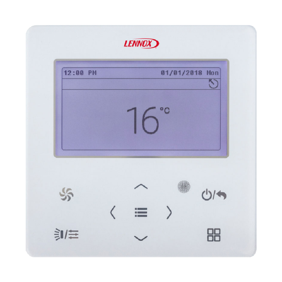
Page 7: Instructions To Appearance And Display
Wired Controller VEWCL1E 3 Instructions to Appearance and Display Fig. 3.1 Outline of wired controller... -
Page 8: Lcd Of Wired Controller
Wired Controller VEWCL1E 3.1 LCD of Wired Controller Fig. 3.2 LCD of air conditioner wired controller Fig. 3.3 LCD of ERV+DX Coil unit wired controller... -
Page 9: Instruction For Lcd Of Wired Controller
Wired Controller VEWCL1E 3.2 Instruction for LCD of Wired Controller Table 3.1 Name Instruction It is for displaying date, time and the activated functional Status icon Mode It is for displaying operating mode Temperature It is for displaying the temperature Swing It is for displaying the current swing status Fan speed... -
Page 10: Instruction For Buttons
Wired Controller VEWCL1E 4.2 Instruction for Buttons Table. 4.1 Instruction for Buttons Name Function Switch fan speed: Auto, Low, Med. Low, Medium,Med. High, and High Turn page Left Move the cursor Right Set and view parameters Set the operating temperature of indoor unit Move the cursor Down Set and view parameters... -
Page 11: Instructions For Status Column
Wired Controller VEWCL1E 5 Instructions for Status Column Table 5.1 Instruction for Status Column of AC Icon Name Instruction Display when the current indoor unit connected by the wired Master controller is master indoor unit (the icon will not be displayed when the wired controller connects to heat recovery unit) Display when one wired controller controls multiple indoor units at Group control... - Page 12 Wired Controller VEWCL1E Icon Name Instruction Timer Display when timer function is activated Clean The status for reminding of cleaning the filter Table 5.2 Instruction for Status Column of ERV+DX Coil IDU Icon Name Instruction Display when the current indoor unit connected by the wired Master controller is master indoor unit (the icon will not be displayed when the wired controller connects to heat recovery unit)
- Page 13 Wired Controller VEWCL1E Icon Name Instruction Memory status (when the unit is re-energized after power failure, Memory the indoor unit will resume to the setting status) Defrost Defrosting status of outdoor unit Timer Display when timer function is activated Clean The status for reminding of cleaning the filter Humidification (Some models are...
-
Page 14: Installation And Commissioning
Wired Controller VEWCL1E 6 Installation and Commissioning Fig. 6.1 Dimension of Wired Controller Fig. 6.2 Parts and Components of Wired Controller Soleplate of Panel of wired Tapping screw ST3.9X25 Name Screw M4×25 wired controller controller... -
Page 15: Instruction Of Wired Controller
Wired Controller VEWCL1E 6.1 Instruction of wired controller 6.1.1 Requirements for model selection of communication wire Fig. 6.3 Length of communication wire Total length of Wire communication line Wire size Material material between indoor unit Remarks /AWG) standard type and wired controller L (m/feet) Light/ (1)Total length of communication... - Page 16 Wired Controller VEWCL1E Notes: If the air conditioner is installed in the place with heavy magnetic field, the ① wired controller must adopt shielded twisted pair. Communication wire material of wired controller must meet the ② requirements of this instruction manual. It is not allowed to use the communication wire not in consistent with the requirements of this instruction manual.
- Page 17 Wired Controller VEWCL1E 6.1.3 Requirements for Wired Connection Network connecting methods between wired controller and indoor unit are as below: Fig. 6.4 one wired controller controls one indoor unit...
- Page 18 Wired Controller VEWCL1E Fig. 6.5 two wired controllers control one indoor unit...
- Page 19 Wired Controller VEWCL1E Fig. 6.6 one wired controller controls multiple indoor units simultaneously Fig. 6.7 two wired controllers control multiple indoor units simultaneously...
- Page 20 Wired Controller VEWCL1E Instruction for wire connection: (1) When one (or two) wired controller controls multiple indoor units simultaneously, the wired controller can connect anyone of indoor unit. Quantity of indoor unit controlled by wired controller is not over 16 sets, and the connected indoor unit should be in the network of the same indoor unit.
- Page 21 Wired Controller VEWCL1E 6.1.4 Installation Fig. 6.8 Installation of Wired Controller...
- Page 22 Wired Controller VEWCL1E Fig. 6.8 shows a simple installation course of wired controller, and the following points should be noted: (1) Before installation, please cut off the power supply of indoor unit, it is not allowed to operate with power supply; (2) Pull out the 2-core twisted pair inside the installation hole in the wall, and thread the wire through the “...
-
Page 23: Engineering Debugging Of Air Conditioner
Wired Controller VEWCL1E 6.1.5 Disassembly Fig. 6.9 Disassembly of wired controller 6.2 Engineering Debugging of Air Conditioner 6.2.1 Inquiry of Parameters Parameters can be viewed under both ON and OFF status. In homepage,press“ ”to enter into menu page, and then select “View” to enter into inquiry page. - Page 24 Wired Controller VEWCL1E (1) IDU project No. View and Locating In the project view page, select “IDU Project No. View and Locating” to enter into IDU project No. view and locating page, as shown below, this page displays IDU project number and IDU error. If there are many indoor units, please press “...
- Page 25 Wired Controller VEWCL1E selected indoor unit will beep until quitting the viewing page or switching to the next indoor unit, the selected indoor unit stops beeping. (2) View All IDU Project No. In project No. viewing page, select “View All IDU Project No.” to enter into the page, as shown below, user can turn on or turn off the function of viewing all the IDU project No.
- Page 26 Wired Controller VEWCL1E shown below, user can view the parameters as shown in table 6.1 and table 6.2. When viewing the IDU parameters, if there are many indoor units, please press “ ” or “ ” button to switch the indoor unit, the interface will display the corresponding parameters of indoor unit, as shown below.
- Page 27 Wired Controller VEWCL1E When viewing the parameters of air box, if there are many air boxes, press “ ” or “ ” button to switch the air box, the interface will display the corresponding parameters of outdoor unit, as shown below.
- Page 28 Wired Controller VEWCL1E Table 6.1 List for Viewing Parameters of Air Conditioner Parameter Name Range Parameter Name Range Wired Controller's Address Number of IDUs 1、2 1~16 Master IDU's Project No. Time Left to Clean Filter 1~255 0~416day Online IDUs of CAN1 1~80 CAN2 Address 1~255...
- Page 29 Wired Controller VEWCL1E Parameter Name Range Parameter Name Range Module High Pressure Module Low Pressure -40~70℃ -69~38℃ Comp1 Discharge Temp Comp2 Discharge Temp -30~150℃ -30~150℃ Comp3 Discharge Temp Comp4 Discharge Temp -30~150℃ -30~150℃ Comp5 Discharge Temp -30~150℃ Comp6 Discharge Temp -30~150℃...
- Page 30 Wired Controller VEWCL1E Parameter Name Range Parameter Name Range PM2.5 0~1000ug/m 400~2000ppm Temp -10℃~50℃ 0~95% IDU Error Log 5 historical errors Prior Operation Yes, no Replacement remaining Cleaning remaining time 0-100% 0-100% time for primary filter for primary filter Replacement remaining Cleaning remaining time for 0-100% time for high-efficiency...
- Page 31 Wired Controller VEWCL1E Parameter Name Range Parameter Name Range Comp2 Operation Freq ODU Fan Operation Freq 0~200Hz 0~100Hz Module High Pressure Module Low Pressure -40~70℃ -69~38℃ Comp1 Discharge Temp Comp2 Discharge Temp -30~150℃ -30~150℃ Comp3 Discharge Temp -30~150℃ Comp4 Discharge Temp -30~150℃...
- Page 32 Wired Controller VEWCL1E Press “ ” or “ ” button to switch the option, press and hold the button can switch quickly; When selecting the right icon “ ” or “ ”, press “ ” button to turn on or turn off the corresponding Press “...
- Page 33 Wired Controller VEWCL1E 6.3 Setting Parameter List of Air Conditioner Item Settable range Default Remarks When it is off, this wired controller is slave wired controller, status column of the homepage displays the icon of Master Wired slave wired controller “ ”, the wired ON, OFF Controller...
- Page 34 Wired Controller VEWCL1E Item Settable range Default Remarks After setting the linkage function, the fresh air IDU will automatically turn on Link with or turn off along with the on and off of ON, OFF Fresh Air IDU general IDU, meanwhile, user can manually turn on or turn off the unit.
- Page 35 Wired Controller VEWCL1E Item Settable range Default Remarks Cooling Temp of Fresh Air 16℃~30℃ 18℃ Only applicable to fresh air IDU. Heating Temp of Fresh Air Only applicable to fresh air IDU. 16℃~30℃ 22℃ Relative Humidity of 65%~85% Auto Dry* Relative Humidity of 65%~85%...
- Page 36 Wired Controller VEWCL1E Table 6.4 Setting Parameter List of ERV+DX Coil Item Settable range Default Remarks When it is off, this wired controller is slave wired controller, status column of the homepage displays the icon of Master wired slave wired controller “ ”, the wired ON, OFF controller...
- Page 37 Wired Controller VEWCL1E Item Settable range Default Remarks One master air box can be set, if many master air boxes are set, the latest one should be the master one. Master Air Box 0-4,—— When setting it as“--”, it indicates the ——...
- Page 38 Wired Controller VEWCL1E Item Settable range Default Remarks 01: very good 02: good Set the outdoor pollution level 03: light pollution according to the pollution degree of Outdoor Air 04: medium different regions. It is used for Pollution Degree pollution calculating the time for reminding 05: high pollution washing and replacing filter.
-
Page 39: Operational Instructions Of Air Conditioner
Wired Controller VEWCL1E Item Settable range Default Remarks Only when the “setting of auto control Auto Control Comfort, Comfort sensor” is set as “multiple” the setting Method* Energy-saving becomes valid; Only applicable to the unit connected Reset WiFi Reset Wifi? Not reset with “G-cloud controller”. -
Page 40: Setting Of Modes
Wired Controller VEWCL1E Fig. 7.1 Unit-ON interface Fig. 7.2 Unit-OFF interface 7.2 Setting of Modes Under ON status, each time pressing the “ ” button in the homepage, the mode will be switched as the following order circularly: Auto-> Cool -> Dry -> Fan -> Heat ->Floor ->3D Heat -> Space -> Auto Note: ①... -
Page 41: Setting Of Temperature
Wired Controller VEWCL1E ③ Instructions for mode switch: a) For heat recovery units, anyone of IDU can switch mode arbitrarily; b) For oher units, the system mode will be subject to the mode of master IDU; the master IDU can switch mode arbitrarily, while the slave IDU cannot switch to the mode which may conflict to the mode of master IDU;... -
Page 42: Setting Of Fan Speed
Wired Controller VEWCL1E Note: ① When the Absence function is activated, the set temperature should not be adjusted via “ ” or “ ” button. ② Under Auto mode, it cannot enter into temperature setting interface, user can only set the cooling and heating temperature of Auto mode in the project parameters setting page. -
Page 43: Setting Of Swing Function
Wired Controller VEWCL1E ③ If auto fan speed is set, indoor unit will change fan speed automatically according to indoor ambient temperature. 7.5 Setting of Swing Function Under ON status, the up and down swing function and left and right swing function are settable. -
Page 44: Setting Of Functions
Wired Controller VEWCL1E (2)Left and right swing function*: Left and right swing function has two modes: simple swing and fixed frame swing. Select “L&R Swing Position” in the functional page,and then press “ ” can switch between simple swing mode and fixed frame swing mode. Under ON status, press “... - Page 45 Wired Controller VEWCL1E function is turned on, if it displays “ ”, it means the function is turned off. When the option (Quiet, Air, Clean, Save) with “>” is selected, press “ ” button will enter into the setting interface of corresponding function. Note: ①...
- Page 46 Wired Controller VEWCL1E Lock: under lock status, any button operation are invalid, user should operate according to the prompt to unlock the function. Light: this function can set the ON and OFF of light in light plate of IDU. Rapid: it is used to fast increase or decrease temperature to the set value when starting the unit.
- Page 47 Wired Controller VEWCL1E Turbo: it is used to turn on the highest fan speed, after turning on the function, fan speed in the homepage displays turbo. 7.6.1 Setting of Quiet Function Quiet: it is used for reducing the noise of IDU to achieve quiet effect. The quiet function has two modes: quiet and auto quiet, which only be valid under Auto, Cool, Dry, Fan, Heat, 3D Heat, and Space modes.
- Page 48 Wired Controller VEWCL1E change the fan speed according to the indoor ambient temperature, when the indoor ambient temperature reaches the set temperature, it will operate under quired fan speed. 7.6.2 Setting of Air Function* Air function: improve the air quality to make the indoor air fresh through adjusting the indoor fresh air volume.
- Page 49 Wired Controller VEWCL1E minutes). Please see the table below. Opening time of fresh air valve indicates the first N minutes within a certain time. For example: if air degree is set to 1, unit starts to count the time and fresh air valve is open. 6 minutes later, fresh air valve is closed while unit continues operating.
- Page 50 Wired Controller VEWCL1E In the functional page select “Save” to enter into Save function setting page, as shown below: Press “ ” or “ ” buton to switch option, when selecting the first option, press “ ” or “ ” button to turn on or turn off; when selecting the second option, press“ ” or “ ” button to switch the mode;...
- Page 51 Wired Controller VEWCL1E 7.6.4 Setting of Filter Clean Reminder Filter Clean Reminder: Air conditioner can record its running time and when it reaches to a certain time, unit can remind user to clean filter. A dirty filter will cause poor cooling and heating effect, malfunction or even generate bacteria. On the function interface, select "Clean"...
- Page 52 Wired Controller VEWCL1E (2)Light pollution: Cleaning degree of current environment is “A”. When clean cycle is “0”, the accumulative running time is 5500 hours. Every increase of "1" indicates an increase of 500 hours in running time. When clean cycle is "9", the accumulative running time is 10000 hours;...
-
Page 53: Gate-Control Function
Wired Controller VEWCL1E 7.7 Gate-control Function When there is Gate-control System, user can insert a card to turn on the unit or pull off a card to turn off the unit. When the card is re-inserted, the unit will recover the operation as state in memory. - Page 54 Wired Controller VEWCL1E In the independent swing page, press “ ” or “ ”button to switch the option, when selecting the first option, press “ ” button to turn on or turn off the independent swing function; when selecting other options, press “ ”...
-
Page 55: Operational Instructions Of Erv+Dx Coil Unit
Wired Controller VEWCL1E When the independent swing function is activated, the position of up and down swing in homepage will display the independent swing icon “ ”. Notes: ① The independent swing function can only set the up and down swing. ②... -
Page 56: Setting Of Modes
Wired Controller VEWCL1E Fig. 8.1 Unit-ON Interface Fig. 8.2 Unit-OFF Interface 8.2 Setting of Modes Under ON status, each time pressing the “ ” button in the homepage, the mode will be switched as the following order circularly: Cool -> Dry -> Fan -> Heat -> Cool Notes: instructions for mode switch: For the Heat Recovery unit, anyone of IDU can switch mode arbitrarily;... -
Page 57: Setting Of Temperature
Wired Controller VEWCL1E IDU; the master IDU can switch mode arbitrarily, while the slave IDU cannot switch to the mode which may conflict to the mode of master IDU; when the master IDU changes the mode and leads to confliction of modes between slave IDU and the system, the operating mode of slave IDU will automatically switch to the system mode. -
Page 58: Setting Of Control Modes
Wired Controller VEWCL1E the indoor ambient temperature more stable and comfortable. ② Only when the control mode is set as auto can the auto fan speed be valid. ③ Fan and control mode of ERV are bound. 8.5 Setting of Control Modes Under on status, the unit will change in the sequence of auto→linkage→operation circularly after pressing “... -
Page 59: Setting Of Functions
Wired Controller VEWCL1E will be started up or stay at the standby status according to the on/off of indoor unit under the CAN network. ② Auto control mode can be started up only when the air box is existed. 8.6 Setting of Functions Under menu page, select “Func”... - Page 60 Wired Controller VEWCL1E lower than the set temperature, it will bring fresh air to lower the indoor temperature, and reduce cooling power consumption to reach energy-saving effect. Free Cooling at night: after this function is activated, when the system shutdown at night (both the air conditioner and ERV+DX Coil unit are turned off), if the outdoor tempberature is lower than the indoor temperature, it will turn on the ERV+DX Coil unit to intake fresh air and lower the indoor temperature, and maintain the indoor...
-
Page 61: Instructions To General Operation
Wired Controller VEWCL1E prevent condensation or frost of whole unit, it will stop intaking fresh air and only conduct air discharge. Auto mode: auto mode is a kind of fresh wind mode which is based on the Fresh Air Inlet Temp, Indoor Ambient Temp as well as related Fresh Air Inlet Humidity. 9 Instructions to General Operation 9.1 Setting of Timer In the homepage, press “... - Page 62 Wired Controller VEWCL1E the system time has been set as the current date and time, if the date and time is not correct, please set the date and time in the “Date&Time” setting page. In the timer 1 page, press “ ”...
-
Page 63: Service Hotline
Wired Controller VEWCL1E In the timer 1 page, select “repeat” to enter into the following setting page, it can set the timer valid time; press “ ” or “ ” button can swith the options, press “ ” button can confirm or cancel corresponding option, press “ ”... - Page 64 Wired Controller VEWCL1E LENNOX. (2) Local After-sales Tel. (3) Select “Local After-sales Tel.” to enter into the viewing and setting page of local after-sales telephone number, as shown below: When the local after-sales telephone number has not been set, there is no telephone number displaying;...
-
Page 65: Setting Of Language
Wired Controller VEWCL1E 9.3 Setting of Language In the setting page, select “Language” to enter into language setting page, Chinese and English version can be set 9.4 Setting of Sound In the setting page, select “Sound” to enter into voice setting page, the voice of button of wired controller can be turned on or turned off. -
Page 66: Display Of Errors
Wired Controller VEWCL1E user conduct remote control or button operation to the wired controller, the “ ” icon flashes to remind the user. 10 Display of Errors If malfunction occurs when system is running, wired controller will display error icon “ ”, error code and project number of the corresponding indoor unit. -
Page 67: Error Code List Of Odu
Wired Controller VEWCL1E 10.1 Error Code List of ODU Code Content Code Content System Pressure Over-Ratio Outdoor Unit Error Protection System Pressure Under-Ratio High Pressure Protection Protection Discharge Low Temperature Protection of Abnormal Protection Pressure Protection of Water Flow Low Pressure Protection Switch Excess Discharge Temperature Protection of Low... - Page 68 Wired Controller VEWCL1E Code Content Code Content Outlet tube temperature sensor error Defrosting Temperature of plate type heat exchanger Sensor 2 Error Compressor 1 Discharge Liquid-out temperature sensor error of subcooler Temperature Sensor Error Compressor 2 Discharge Air-out temperature sensor Temperature Sensor Error error of subcooler Compressor 3 Discharge...
- Page 69 Wired Controller VEWCL1E Code Content Code Content Malfunction of exit tube Mode Exchanger Inlet Pipe temperature sensor of Temperature Sensor Error condenser High and low pressure sensors Water-out temperature sensor error are connected inversely Compressor Discharge Oil-return 2 temperature Temperature Sensor Error sensor error Mode Exchanger Outlet Pipe Oil-return 3 temperature...
- Page 70 Wired Controller VEWCL1E Code Content Code Content Compressor 2 Over-current Protection of Compressor Protection Drive Board Power Supply Compressor 3 Over-current Protection of Compressor Protection Drive Board Module Reset Compressor 4 Over-current Error of Fan Drive Board Protection Compressor 5 Over-current Malfunction of Fan Drive Board Protection Compressor 6 Over-current...
-
Page 71: Error Code List Of Idu
Wired Controller VEWCL1E 10.2 Error Code List of IDU Code Content Code Content Indoor Unit Error Swing Assembly Error Water temperature sensor Indoor Fan Protection error Inlet Pipe Temperature Sensor E-heater Protection 2 Error Outlet Pipe Temperature Water Full Protection Sensor 2 Error Middle tube temperature Wired Controller Power Supply Error... - Page 72 Wired Controller VEWCL1E Code Content Code Content Inconsistency of Group-controlled Air-return outlet temperature Indoor Units in Reheat sensor error Dehumidification System Shunt Valve Setting Error High liquid level switch error Wrong Setting of Function DIP Low liquid level switch error Switch Outdoor-Indoor Incompatibility Error Low voltage of IDU bus bar...
- Page 73 Wired Controller VEWCL1E Code Content Code Content High module temperature of Water Temperature Abnormality Temperature sensor error of Jumper Cap Error IDU module Indoor Unit Hardware Address Error IDU charging circuit error Wired Controller PC-Board Error Moder driver error Capacity DIP Switch Setting Error. Indoor CO sensor error Outlet Air Temperature...
-
Page 74: Code List For Debugging
Wired Controller VEWCL1E 10.3 Code List for Debugging Code Content Code Content Outdoor Unit Capacity Code/Jumper No master control unit error Cap Setting Error Phase Sequence Protection of Power Communication error between mode Supply switch and IDU Protection of Lack of Refrigerant Multiple master control units error Wrong Address of Compressor Drive IP address allocation overflow... - Page 75 Wired Controller VEWCL1E Code Content Code Content Undervoltage protection of DC bus Alarm of Wrong Number of Outdoor bar in power grid side Unit Indoor Unit Identification Error of Mode Exchanger Communication Mode Exchanger Error Emergency Operation DIP switch Rated capacity is too high. setting of the compressor is wrong.
-
Page 76: Code List For Status
Wired Controller VEWCL1E 10.4 Code List for Status Code Content Code Content Unit is waiting for debugging. Lock status Check the compressor operation Shielding status parameters. After-sales Refrigerant Reclaim Compulsory defrosting Compulsory IDU project No. Defrosting deflection Oil return Object low pressure revision Anti-high temperature of Online Testing heating... - Page 77 Wired Controller VEWCL1E Code Content Code Content Filter Clean Reminder Setting of static pressure Remote Urgent Stop EVI Operating Mode System compulsory cooling Emergency Stop mode Setting of target degree of Operation Restriction super-cooling of ODU Working mode of compressor heating belt...
- Page 80 Contact us at +1-305-718-2901 lennoxglobalhvac@lennoxintl.com 2019 Lennox Industries Inc. For a complete list of the registered and common law trademarks owned by Lennox Industries Inc., please visit www.lennox.com...
Need help?
Do you have a question about the VRF VEWCL1E and is the answer not in the manual?
Questions and answers